Patent application title: OUTDOOR UNIT AND AIR-CONDITIONING APPARATUS
Inventors:
Tatsuya Mochizuki (Tokyo, JP)
Yoshihiro Tanabe (Tokyo, JP)
Kenta Kawahara (Tokyo, JP)
Toshiyuki Kubono (Tokyo, JP)
Toshiyuki Kubono (Tokyo, JP)
Hiroyuki Jinnai (Tokyo, JP)
Hiroyuki Jinnai (Tokyo, JP)
IPC8 Class: AF25B4500FI
USPC Class:
62125
Class name: Refrigeration with indicator or tester
Publication date: 2016-05-12
Patent application number: 20160131404
Abstract:
An outdoor unit includes at least one of a hexagonal sealing nut and
attention attracting means that needs to be operated by an operator when
removing a hexagonal sealing nut.Claims:
1. An outdoor unit including a refrigerant pipe connecting valve having a
refrigerant charging service port that is sealed by a hexagonal sealing
nut, the hexagonal sealing nut being removed when charging refrigerant,
the outdoor unit comprising: an indication portion indicating at least
one of a type of refrigerant that is used and a precautions text; and a
projection portion that attaches the indication portion to one of the
refrigerant pipe connecting valve and the hexagonal sealing nut.
6. The outdoor unit of claim 1, wherein the indication portion is held on at least one of surfaces defining a hexagonal prism shape of the hexagonal sealing nut by the projection portion.
7. The outdoor unit of claim 1, wherein the projection portion is provided with a C-shaped attachment portion, and wherein the projection portion is attached to the refrigerant pipe connecting valve, by fitting the attachment portion onto the refrigerant pipe connecting valve using an elastic force of the attachment portion.
8. (canceled)
9. The outdoor unit of claim 1, wherein the projection portion is provided with a ring-shaped attachment portion, and wherein the projection portion is attached to the hexagonal sealing nut, by fitting the attachment portion onto a hexagonal-prism-shaped portion of the hexagonal sealing nut.
10. (canceled)
11. The outdoor unit of claim 1, wherein the projection portion is provided with a C-shaped attachment portion, wherein a groove is formed in at least a part of a hexagonal-prism-shaped portion of the hexagonal sealing nut, and wherein the projection portion is attached to the hexagonal sealing nut, by fitting the attachment portion into the groove of the hexagonal sealing nut using an elastic force of the attachment portion.
12. An outdoor unit including a refrigerant pipe connecting valve having a refrigerant charging service port that is sealed by a hexagonal sealing nut, the hexagonal sealing nut being removed when charging refrigerant, the outdoor unit comprising: a cylindrical indication cover indicating at least one of a type of refrigerant that is used and a precautions text and covering an outer periphery of a hexagonal-prism-shaped portion of the hexagonal sealing nut.
13. The outdoor unit of claim 12, wherein the indication cover is attached to a side panel defining a side surface of a casing of the outdoor unit via a coupling portion.
14. The outdoor unit of claim 13, wherein the coupling portion is formed integrally with the indication cover.
15. (canceled)
16. The outdoor unit of claim 13, wherein a distal end of the coupling portion which is attached to the side panel includes a distal locking portion that abuts an inner surface of the side panel, and a rib that is disposed at a proximal end side with respect to the distal locking portion, and adheres to an outer surface of the side panel.
17. The outdoor unit of claim 13, wherein a drain hole is formed in at least a part of a bottom surface of the indication cover.
18. The outdoor unit of claim 1, wherein the projection portion is provided with a ring-shaped attachment portion, and wherein the projection portion is attached to the refrigerant pipe connecting valve, by attaching the attachment portion to the hexagonal sealing nut while the attachment portion is fitted on a neck of a thread portion of the refrigerant charging service port.
19-20. (canceled)
21. An outdoor unit including a refrigerant pipe connecting valve having a refrigerant charging service port that is sealed by a hexagonal sealing nut, the hexagonal sealing nut being removed when charging refrigerant, the outdoor unit comprising: an indication portion indicating at least one of a type of refrigerant that is used and a precautions text, and detachably covering a hexagonal-prism-shaped portion of the hexagonal sealing nut, an attachment portion that is attached to a base portion of the refrigerant pipe connecting port of the refrigerant pipe connecting valve, and an extension portion that connects the indication portion and the attachment portion to each other.
22. An air-conditioning apparatus comprising: the outdoor unit of claim 1; and an indoor unit that is connected to the outdoor unit.
23. The outdoor unit of claim 21, wherein the extension portion has a shape extending from one surface of the indication portion toward the refrigerant pipe connecting port of the refrigerant pipe connecting valve, and wherein the indication portion and the extension portion are flexibly coupled.
24. The outdoor unit of claim 21, wherein the extension portion is formed in a shape of a string.
25. The outdoor unit of claim 1, wherein the hexagonal sealing nut that requires an operation using a dedicated tool is provided, and wherein the hexagonal sealing nut corresponds to the refrigerant charging service port having a thread diameter of 1/2 inch or less, and has a width across flats of 18 mm or greater.
26. The outdoor unit of claim 1, wherein a type of refrigerant is indicated on at least one surface of a hexagonal-prism-shaped portion of the hexagonal sealing nut.
Description:
TECHNICAL FIELD
[0001] The present invention relates to an outdoor unit of an air-conditioning apparatus including a compression refrigeration cycle, and particularly relates to an outdoor unit and an air-conditioning apparatus that provide improved safety and reliability during installation of the air-conditioning apparatus and during service work thereon.
BACKGROUND ART
[0002] Conventionally, refrigerants such as R22 that is based on hydrochloroflourocarbon (HCFC) and R410A that is based on hydrofluorocarbon (HFC) have often been used in air-conditioning apparatuses. Many of the current and existing air-conditioning apparatuses use R22 or R410A. In Japan, apparatuses using R410A are now the mainstream on the market. Even taking the existing air-conditioning apparatuses into account, R410A apparatuses are assumed to be dominant.
[0003] In recent years, however, from the perspective of protecting the ozone layer and preventing global warming, attention has come to be paid to the following refrigerants: R32 (difluoromethane), which is a flammable HFC-based refrigerant; hydrofluoroolefin-based refrigerants (such as HFO1234yf, and HFO1234ze); refrigerant mixtures containing R32 and any HFO-based refrigerant; and natural refrigerants such as R290 (propane) and R600a (isobutane). In particular, the HFC-based refrigerant R32 and the HC-based refrigerant R290 (propane) have come to attract attention as alternative refrigerants. The refrigerants R32 and R290 have global warming potentials (hereinafter referred to as GWPs) much lower than those of other refrigerants such as R22 and R410A, when released into the atmosphere.
[0004] However, since the refrigerants such as R32 and R290 are flammable, products that use these refrigerants need to be designed with full consideration for safety. The refrigerant R290 is highly flammable, and needs to be handled with special care. The refrigerant R32 is less flammable than R290, and therefore product design relatively similar to that for the non-flammable refrigerants R22 and R410A is possible. Nevertheless, since R32 is flammable, safety design is needed. Therefore, in the case of using a flammable refrigerant such as R32 and R290, a certain amount of money needs to be spent in order to improve the safety.
[0005] An air-conditioning apparatus includes a compression refrigeration cycle in which a compressor, an outdoor heat exchanger, an indoor heat exchanger, a four-way valve, a pressure reducing device, and so on are connected to each other by refrigerant pipes. Therefore, in the case of an air-conditioning apparatus using a flammable refrigerant such as R32 and R290, safety design is particularly necessary in view of situations such as when charging refrigerant into the refrigerant circuit during installation of the air-conditioning apparatus or during service work on the air-conditioning apparatus, for example.
[0006] As an example of such an air-conditioning apparatus, there has been disclosed "a cooling apparatus having an inlet port for charging refrigerant into a refrigerant circuit, the cooling apparatus including an indication portion that is disposed in the vicinity of the inlet port and that indicates the type of refrigerant used" (see, for example, Patent Literature 1).
CITATION LIST
Patent Literature
[0007] Patent Literature 1: Japanese Unexamined Patent Application Publication No. 10-311629 (see FIG. 2 etc.)
SUMMARY OF INVENTION
Technical Problem
[0008] According to the technique disclosed in Patent Literature 1, the type of refrigerant used is indicated in the vicinity of the inlet port (service port) for charging refrigerant. By attracting attention in this way, the type of refrigerant is indicated to the operator. However, depending on the installation site of the air-conditioning apparatus, the air-conditioning apparatus may have to be installed under unfavorable conditions (for example, the work site is dark, or the operator needs to perform work in an unnatural posture). Then, the operator might overlook the indication and use a wrong refrigerant. Therefore, simply indicating the type of refrigerant according to the technique disclosed in Patent Literature 1 is not sufficient enough to inform the operator of the content of the indication with 100% reliability.
[0009] Particularly, in the case of using a flammable refrigerant such as R32 or R290, safety cannot be assured unless the risk of the indication being overlooked is completely eliminated even when the operator has to perform installation work under unfavorable conditions. Accordingly, it is necessary to definitely inform the operator of the type of the refrigerant used, in a more reliable way than before.
[0010] Furthermore, in the future, as the replacement of refrigerant is promoted, the number of types of refrigerant to be handled increases. Thus, the risk that the operator who performs service work charges a wrong refrigerant by mistake is likely to increase. This leads to a significant loss of safety and reliability.
[0011] For example, the existing air-conditioning apparatuses using R22 or R410A do not have safety design for flammable refrigerants. Suppose that a flammable refrigerant is mistakenly charged into such an existing air-conditioning apparatus. Then, if the refrigerant leaks while installation work or service work is performed, or if the refrigerant leaks due to damage to the refrigerant circuit while the air-conditioning apparatus is used, a flammable concentration may be reached in the ambient air. Thus, if there is any ignitable matter, the refrigerant might catch fire, resulting in a serious incident.
[0012] On the other hand, if the refrigerant R22 or R410A is mistakenly charged into an air-conditioning apparatus that uses a flammable refrigerant, the inside of the compressor might wear or the cooling and heating performance might be reduced, resulting in a significant reduction in reliability. This is because, for example, as for refrigerating machine oil in particular, an appropriate type of refrigerating machine oil is selected in accordance with the type of refrigerant.
[0013] In order to prevent a wrong refrigerant from being charged during installation of the air-conditioning apparatus or during service work thereon, the port diameter of a charging portion of a refrigerant charging port may be changed in accordance with the type of refrigerant. This can be a straightforward measure to prevent a wrong refrigerant from being charged. However, if the port diameter of the charging portion of the refrigerant charging port is changed in accordance with the type of refrigerant, the types of a charging hose for charging refrigerant, a tank (cylinder) for storing refrigerant, and equipment for vacuuming the refrigerant circuit also need to be changed. Accordingly, the equipment service provider that offers installation work and service work needs to prepare new appropriate equipment, leading to a significant cost increase. Moreover, if the operator goes to an installation site or a service site without taking such equipment, the operator cannot perform the expected work, leading to a serious trouble.
[0014] In April 2001, the Home Appliance Recycling Law was enforced. In compliance with this law, certain types of waste products that are large in quantity, including air-conditioning apparatuses, refrigerators, and televisions, are collected to recycling centers. In such a recycling center, the waste products are subject to a disassembling process and a sorting process that are manually performed by the operators, a product crushing process that is performed using a crushing machine, and a sorting process that is performed using a sorting machine for sorting the resulting materials into iron, copper, aluminum, plastic, and other categories. In addition, in the recycling center, if the waste products include air-conditioning apparatuses, the refrigerant contained in each of the air-conditioning apparatuses is collected by the operator.
[0015] Upon reusing iron, copper, and aluminum, these materials are melted by high-temperature processing, and therefore the influence of foreign substances, impurities, contaminants, or the like adhering thereto is small. Accordingly, these materials are easy to reuse, and are reused as valuables. Plastic varies in material and color, and therefore it is difficult to recycle plastic. In recent years, however, sorting of plastic materials has become possible, and many plastic materials have come to be reused.
[0016] Furthermore, in April 2013, the Act on Ensuring the Implementation of Recovery and Destruction of Fluorocarbons concerning Designated Products was partially revised. This has created asocial trend of requiring efforts to recycle used fluorocarbons. Accordingly, in recycle centers, refrigerant needs to be collected with increased purity in order to facilitate the recycling and reuse of collected refrigerant.
[0017] The present invention has been made to overcome the above problems, and aims to provide an outdoor unit and an air-conditioning apparatus that provide increased safety and reliability by making the operator (the operator who performs installation work, the operator who performs service work, and the operator who performs recycling work) surely recognize the type of refrigerant.
Solution to Problem
[0018] An outdoor unit according to the present invention includes a refrigerant pipe connecting valve having a refrigerant charging service port which is sealed by a hexagonal sealing nut that is removed when charging refrigerant. The outdoor unit includes at least one of: a structure that makes the hexagonal sealing nut different from another hexagonal sealing nut which is provided on a refrigerant charging service port used for another type of refrigerant, in at least one of outer diameter, shape, and appearance; and attention attracting means that requires an operation by an operator when removing the hexagonal sealing nut.
[0019] An air-conditioning apparatus according to the present invention includes the outdoor unit described above, and an indoor unit that is connected to the outdoor unit.
Advantageous Effects of Invention
[0020] With the outdoor unit according to the present invention, it is possible to prevent the operator from mistakenly charging a wrong refrigerant when performing a refrigerant charging work, and thus to increase the safety.
[0021] With the outdoor unit according to the present invention, since the above-described outdoor unit is provided, it is possible to suppress a reduction in performance and quality.
BRIEF DESCRIPTION OF DRAWINGS
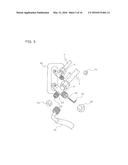
[0022] FIG. 1 is a schematic diagram illustrating the overall configuration of an air-conditioning apparatus including an outdoor unit according to Embodiment 1 of the present invention.
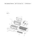
[0023] FIG. 2 is an exploded perspective view illustrating the configuration of an indoor unit of the air-conditioning apparatus including the outdoor unit according to Embodiment 1 of the present invention.
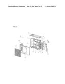
[0024] FIG. 3 is an exploded perspective view illustrating the configuration of the outdoor unit according to Embodiment 1 of the present invention.
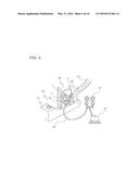
[0025] FIG. 4 is an enlarged view illustrating a part of a side surface of the outdoor unit according to Embodiment 1 of the present invention.
[0026] FIG. 5 is an explanatory view for explaining the procedure of charging refrigerant.
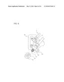
[0027] FIG. 6 is a further enlarged view illustrating a part of the side surface of the outdoor unit according to Embodiment 1 of the present invention.
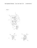
[0028] FIG. 7 is an explanatory view for explaining the specifications of a pipe connecting valve of an outdoor unit according to Embodiment 2 of the present invention.
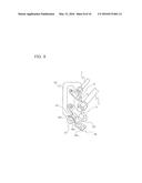
[0029] FIG. 8 is an explanatory view for explaining the specifications of a pipe connecting valve of an outdoor unit according to Embodiment 3 of the present invention.
[0030] FIG. 9 is an explanatory view for explaining the specifications of a pipe connecting valve of an outdoor unit according to Embodiment 4 of the present invention.
[0031] FIG. 10 is an explanatory view for explaining the specifications of a pipe connecting valve of an outdoor unit according to Embodiment 5 of the present invention.
[0032] FIG. 11 is an explanatory view for explaining the specifications of a pipe connecting valve of an outdoor unit according to Embodiment 6 of the present invention.
[0033] FIG. 12 is an explanatory view for explaining the specifications of a pipe connecting valve of an outdoor unit according to Embodiment 7 of the present invention.
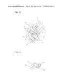
[0034] FIG. 13 is an explanatory view for explaining the specifications of the pipe connecting valve of the outdoor unit according to Embodiment 7 of the present invention.
[0035] FIG. 14 is an explanatory view for explaining the specifications of the pipe connecting valve of the outdoor unit according to Embodiment 7 of the present invention.
[0036] FIG. 15 is an explanatory view for explaining the specifications of a pipe connecting valve of an outdoor unit according to Embodiment 8 of the present invention.
[0037] FIG. 16 is an explanatory view for explaining the specifications of the pipe connecting valve of the outdoor unit according to Embodiment 8 of the present invention.
[0038] FIG. 17 is an explanatory view for explaining the specifications of the pipe connecting valve of the outdoor unit according to Embodiment 8 of the present invention.
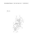
[0039] FIG. 18 is an explanatory view for explaining the specifications of a pipe connecting valve of an outdoor unit according to Embodiment 9 of the present invention.
[0040] FIG. 19 is an explanatory view for explaining the specifications of the pipe connecting valve of the outdoor unit according to Embodiment 9 of the present invention.
DESCRIPTION OF EMBODIMENTS
[0041] Embodiments of the present invention will now be described with reference to the drawings. In the drawings including FIG. 1 to be referred to below, the dimensional relationship between the elements may be different from the actual one. Further, in the drawings including FIG. 1 to be referred to below, like reference numerals denote like or equivalent elements, and this applies throughout the specification. Furthermore, the modes of the elements that will be described in the specification are only examples, and the present invention is not limited thereto.
Embodiment 1
[0042] FIG. 1 is a schematic diagram illustrating the overall configuration of an air-conditioning apparatus A including an outdoor unit 2 according to Embodiment 1 of the present invention. FIG. 2 is an exploded perspective view illustrating the configuration of an indoor unit 1. FIG. 3 is an exploded perspective view illustrating the configuration of the outdoor unit 2. The configuration of the air-conditioning apparatus A will now be described with reference to FIGS. 1 through 3. The outdoor unit 2 is configured such that the operator (for example, the operator who installs the air-conditioning apparatus A, the operator who performs service work on the air-conditioning apparatus A, and the operator who performs recycling work on the air-conditioning apparatus A) surely recognizes the type of refrigerant contained in the air-conditioning apparatus A.
[0043] The air-conditioning apparatus A is applied as, for example, a separate-type home air-conditioning apparatus, and includes the indoor unit 1 and the outdoor unit 2. The indoor unit 1 is hung and fixed on an installation plate 21 that is fixed to, for example, an indoor wall with screws 59 or the like. The indoor unit 1 supplies conditioned air into an air-conditioned space. The outdoor unit 2 is placed and fixed on support blocks 51 that are disposed in a space (for example, an outdoor space) different from the air-conditioned space. The outdoor unit 2 supplies cooling energy or heating energy to the indoor unit 1. The outdoor unit 2 is preferably installed at, for example, a position where an air passage is reserved during operation and which is not very far from the indoor unit 1.
[0044] A liquid-side pipe connecting joint 12 and a gas-side pipe connecting joint 13 are connected to the indoor unit 1. A liquid-side pipe connecting valve 8 and a gas-side pipe connecting valve 9 are connected to the outdoor unit 2. The liquid-side pipe connecting joint 12 of the indoor unit 1 and the liquid-side pipe connecting valve 8 of the outdoor unit 2 are connected to each other by a flared extension pipe (refrigerant pipe) 7. Likewise, the gas-side pipe connecting joint 13 of the indoor unit 1 and the gas-side pipe connecting valve 9 of the outdoor unit 2 are connected to each other by another flared extension pipe 7. Thus, the components of the indoor unit 1 and the components of the outdoor unit 2 are connected to each other by piping, whereby a refrigerant circuit is formed.
[0045] In order to electrically connect the indoor unit 1 and the outdoor unit 2 to each other a terminal block 20 of the indoor unit 1 and a terminal block 17 of the outdoor unit 2 are connected to each other by a VVF cable 22. The liquid-side pipe connecting valve 8, the gas-side pipe connecting valve 9, and the terminal block 17 of the outdoor unit 2 are disposed at positions where the intended work can be performable by detaching a pipe decorative cover 10 from the outdoor unit 2. That is, the pipe decorative cover 10 is detachably attached to a side surface of the outdoor unit 2.
(Indoor Unit 1)
[0046] The indoor unit 1 includes a base 52, an indoor heat exchanger 11, an indoor blower motor 18, a blower fan 19, an electric component box 53, a casing 54, and an openable and detachable front design panel 55. The base 52 is fixed to the installation plate 21. The indoor heat exchanger 11, the indoor blower motor 18, the blower fan 19, the electric component box 53, and the terminal block 20 are attached to the base 52. In this state, the casing 54 is fixed to the base 52 by screws. That is, the indoor heat exchanger 11, the indoor blower motor 18, the blower fan 19, the electric component box 53, and the terminal block 20 are covered with the casing 54. The front design panel 55 is attached to the casing 54.
[0047] The indoor heat exchanger 11 functions as a condenser (radiator) during a heating operation, and as an evaporator during a cooling operation. The indoor blower motor 18 and the blower fan 19 are disposed in front of the indoor heat exchanger 11, and send air to the indoor heat exchanger 11. The electric component box 53 accommodates an indoor driving device 56 that drives the indoor blower motor 18. The terminal block 20 is for electrical connection to the outdoor unit 2.
[0048] The indoor unit 1 has an air inlet 57 for introducing air from the air-conditioned space. The air inlet 57 is formed in the upper surface of the casing 54. The indoor unit 1 also has an air outlet 58 formed at the lower front of the casing 54. The air taken from the air inlet 57 passes through the indoor heat exchanger 11, where the air exchanges heat. Then, the conditioned air is blown from the air outlet 58 into the air-conditioned space.
(Outdoor Unit 2)
[0049] The outdoor unit 2 includes a compressor 3 that compresses the refrigerant and is of, for example, a variable rotation speed type, a four-way valve 4 that switches the flow of the refrigerant, an outdoor heat exchanger 5 that functions as an evaporator during a heating operation and as a condenser (radiator) during a cooling operation, a flow rate control device 6 (a pressure reducing device) that reduces the pressure of the refrigerant, and an outdoor blower motor 15 and an outdoor fan 16 that send air to the outdoor heat exchanger 5. The outdoor unit 2 has a casing that includes a panel 62 defining the front surface and one side surface, a top plate 65 defining the top surface, and a side panel 66 defining another side surface.
[0050] The panel 62 has an opening 63 at a position facing the outdoor fan 16. The opening 63 allows air to pass therethrough. A fan guard 64 that is formed of wires is attached on the opening 63. The side panel 66 has an opening 68 from which the VVF cable 22 is exposed. The VVF cable 22 exposed from the opening 68 of the side panel 66 is covered with a cable cover 67. The cable cover 67 is further covered with the pipe decorative cover 10. The outdoor unit 2 also includes a driving device 14 that drives the compressor 3, the four-way valve 4, and the outdoor blower motor 15, and the terminal block 17 that is for electrical connection to the indoor unit 1.
(Refrigerant Circuit)
[0051] The indoor heat exchanger 11 of the indoor unit 1, the compressor 3, the four-way valve 4, the outdoor heat exchanger 5, and the flow rate control device 6 of the outdoor unit 2 are connected to each other by piping, whereby a refrigerant circuit is formed. Specifically, the refrigerant circuit is configured such that the refrigerant flows through the compressor 3, the four-way valve 4, the indoor heat exchanger 11, the flow rate control device 6, and the outdoor heat exchanger 5 in this order during a heating operation, whereas the refrigerant flows through the compressor 3, the four-way valve 4, the outdoor heat exchanger 5, the flow rate control device 6, and the indoor heat exchanger 11 in this order during a cooling operation. The four-way valve 4 may be omitted, and thus only one of the cooling operation and the heating operation may be performed. The four-way valve 4 may be replaced with, for example, a plurality of two-way valves or three-way valves that are configured to be capable of switching the flow of the refrigerant in the same way.
(Refrigerant)
[0052] Examples of the refrigerant that circulates through the refrigerant circuit of the air-conditioning apparatus A include the flammable refrigerant R32. However, the refrigerant to be used in the air-conditioning apparatus A is not limited to R32. For example, any of the following refrigerants may be employed: other flammable refrigerants (such as R290); natural refrigerants such as carbon dioxide (CO2), hydrocarbons, and helium; and chlorine-free refrigerants including alternative refrigerants such as R410A, R407C, and R404A.
(Method of Installing Air-Conditioning Apparatus A)
[0053] A method of installing the air-conditioning apparatus A will now be described.
[0054] First, the installation plate 21 for fixing the indoor unit 1 is fixed to the indoor wall with the screws 59 or the like. The indoor unit 1 is hung and fixed on the installation plate 21.
[0055] Then, the outdoor unit 2 is disposed at a position where an air passage is reserved during operation and which is not very far from the indoor unit 1 (for example, in the space around the house, on the balcony, on the roof, in the garage, in the yard, and the like).
[0056] Subsequently, in order to form the refrigerant circuit of the air-conditioning apparatus A, the liquid-side pipe connecting joint 12 of the indoor unit 1 and the liquid-side pipe connecting valve 8 of the outdoor unit 2 are connected to each other by one of the flared extension pipes 7. Likewise, the gas-side pipe connecting joint 13 of the indoor unit 1 and the gas-side pipe connecting valve 9 of the outdoor unit 2 are connected to each other by the other one of the flared extension pipes 7. Furthermore, in order to electrically connect the indoor unit 1 and the outdoor unit 2 to each other, the terminal block 20 of the indoor unit 1 and the terminal block 17 of the outdoor unit 2 are connected to each other by the VVF cable 22.
[0057] Subsequently, the pipe decorative cover 10 is attached to the side surface of the outdoor unit 2 so as to cover the liquid-side pipe connecting valve 8, the gas-side pipe connecting valve 9, and the terminal block 17 of the outdoor unit 2.
[0058] In general, each of the two extension pipes 7 is covered with a heat insulator 60. Then, the two extension pipes 7 covered with the respective heat insulators 60 are wrapped together with tape 61.
[0059] FIG. 4 is an enlarged view illustrating a part of the side surface of the outdoor unit 2. FIG. 5 is an explanatory view for explaining the procedure of charging refrigerant. A typical procedure for charging refrigerant will now be described with reference to FIGS. 4 and 5.
[0060] As illustrated in FIG. 4, the gas-side pipe connecting valve 9 has a refrigerant charging service port 23. A charging hose 26 connected to a vacuum pump 25 is connected to the refrigerant charging service port 23. A pressure gauge 27 is connected between the vacuum pump 25 and the refrigerant charging service port 23.
[0061] As illustrated in FIG. 5, the gas-side pipe connecting valve 9 has a gas-pipe-side stem 30, in addition to the refrigerant charging service port 23. A hexagonal sealing nut (cap) 24 that seals the refrigerant charging service port 23 is disposed on the refrigerant charging service port 23. A push-pin valve 33 is disposed in the refrigerant charging service port 23. Further, a hexagonal stem nut (cap) 28 is disposed on the gas-pipe-side stem 30. The gas-pipe-side stem 30 is operable with a hexagonal key 29. The liquid-side pipe connecting valve 8 has a liquid-pipe-side stem 32. A hexagonal stem nut (cap) 31 is disposed on the liquid-pipe-side stem 32. The liquid-pipe-side stem 32 is operable with the hexagonal key 29.
[0062] At the time when the indoor unit 1 and the outdoor unit 2 are connected to each other by the extension pipes 7, the extension pipes 7 and the pipes included in the indoor heat exchanger 11 of the indoor unit 1 are filled with air. Therefore, the air needs to be released. Thus, in the outdoor unit 2, the hexagonal sealing nut 24 disposed on the refrigerant charging service port 23 of the gas-side pipe connecting valve 9 is removed, and the charging hose 26 of the vacuum pump 25 is connected to the refrigerant charging service port 23. Then, vacuuming is performed. Completion of the vacuuming is determined using the pressure gauge 27 or the like.
[0063] After completion of the vacuuming, the hexagonal stem nut 28 on the gas-side pipe connecting valve 9 is removed, and the gas-pipe-side stem 30 is operated with the hexagonal key 29, whereby the gas-side pipe connecting valve 9 is opened. The liquid-side pipe connecting valve 8 is opened in the same manner. That is, the hexagonal stem nut 31 is removed, and the liquid-pipe-side stem 32 is operated with the hexagonal key 29, whereby the liquid-side pipe connecting valve 8 is opened. When the gas-side pipe connecting valve 9 and the liquid-side pipe connecting valve 8 are opened, the refrigerant that is charged in the outdoor unit 2 in advance at the time of manufacture fills the extension pipes 7 and the indoor heat exchanger 11. Thus, the indoor unit 1 and the outdoor unit 2 are connected to each other, whereby a refrigerant circuit is formed.
[0064] In the case where, for example, the extension pipes 7 are long, the amount of refrigerant charged in the outdoor unit 2 in advance at the time of manufacture may be insufficient. In such a case, an additional amount of refrigerant needs to be charged. In doing so, the operator charges a required amount of refrigerant from a refrigerant cylinder that is prepared in advance through the refrigerant charging service port 23. In this step, the operator needs to carefully check that the type of refrigerant contained in the air-conditioning apparatus A and the type of refrigerant contained in the prepared refrigerant cylinder are the same.
[0065] When the charging of the refrigerant is completed, the operator tightens the hexagonal stem nut 31 onto the liquid-side pipe connecting valve 8, the hexagonal stem nut 28 onto the gas-side pipe connecting valve 9, and the hexagonal sealing nut 24 onto the refrigerant charging service port 23, by using a wrench. Finally, the operator attaches the pipe decorative cover 10 to the outdoor unit 2. Thus, a series of steps are completed.
(Recognition of Type of Refrigerant)
[0066] FIG. 6 is a further enlarged view illustrating a part of the side surface of the outdoor unit 2. The following describes how the operator recognizes the type of refrigerant contained in the air-conditioning apparatus A, with reference to FIG. 6.
[0067] As mentioned above, the liquid-side pipe connecting valve 8 and the gas-side pipe connecting valve 9 are provided on the side surface of the outdoor unit 2. Further, the refrigerant charging service port 23 is provided in the gas-side pipe connecting valve 9. As described with reference to FIG. 5, at the installation site, the operator removes the hexagonal sealing nut 24, and then attaches the charging hose 26 for charging refrigerant to the refrigerant charging service port 23. Thus, the push-pin valve 33 disposed in the refrigerant charging service port 23 is opened so as to allow the refrigerant to be charged.
[0068] The hexagonal sealing nut 24 that is used in the currently most widely used R410A air-conditioning apparatuses is of the 1/2 inch thread specifications. Further, the hexagonal sealing nut 24 has a width across flats of 17 mm. However, if the hexagonal sealing nut 24 with such specifications is used, in the case where a type of refrigerant different from R410A is contained in the installed air-conditioning apparatus, the operator is likely to charge a wrong type of refrigerant.
[0069] The hexagonal sealing nut 24 corresponds to a "hexagonal sealing nut which is provided on another refrigerant charging service port" of the present invention.
[0070] In view of the above, as illustrated in FIG. 6, a hexagonal nut (hereinafter referred to as a hexagonal sealing nut (cap) 34) having a width across flats of 18 mm or greater, which is greater than that of the currently most widely used hexagonal sealing nut 24, is used in the outdoor unit 2. The use of the hexagonal sealing nut 34 prevents the use of a wrench that is usually used for the hexagonal sealing nut 24 by the operator. That is, the operator needs to use a wrench (tool) dedicated to the hexagonal sealing nut (cap) 34. Therefore, in the step in which the operator removes the hexagonal sealing nut 34, it is possible to make the operator recognize that a type of refrigerant different from the conventional refrigerant is used, and thus the effect of attracting attention can be expected.
[0071] That is, by setting the width across flats of the hexagonal sealing nut 34 to a width that prevents the use of a wrench that is usually used, even if the operator is wrong about the type of refrigerant used, it is possible to make the operator recognize that a refrigerant different from the conventional refrigerant is used, when removing the hexagonal sealing nut 34. The hexagonal sealing nut 34 does not need to be different from the hexagonal sealing nut 24 in diameter, and only needs to be configured so as to be different in at least one of outer diameter, shape, and appearance so as to prevent the use of the wrench that is usually used (the wrench for the hexagonal sealing nut 24). Further, the use of the hexagonal sealing nut 34 makes it possible to create a safety design particularly for the case where a flammable refrigerant such as R32 and R290 is used, without spending a large amount of money.
[0072] Further, as illustrated in FIG. 6, by providing an indication 35 indicating the type of refrigerant in the form of engraving, a sticker, or the like, on at least one surface of the hexagonal-prism-shaped portion of the hexagonal sealing nut 34, it is possible to clearly inform the operator of the type of refrigerant used.
[0073] Although FIG. 6 has been described in conjunction with the example in which R32 is used, the type of refrigerant used is not limited to R32. However, the advantageous effects are enhanced in the case where a flammable refrigerant, such as R32 and R290, is used that requires a large amount of money for safety design. Further, the width across flats of the hexagonal sealing nut 34 is not limited to the value that is given as an example.
<Advantageous Effects Produced by Outdoor Unit 2>
[0074] As described above, according to the outdoor unit 2, by changing the configuration of a part (hexagonal sealing nut) that the operator always holds in their hand when charging refrigerant, it is possible to more reliably make the operator recognize the type of refrigerant used, than by using the method of simply applying a sticker or the like indicating the type of refrigerant in the vicinity of a connecting valve. This prevents the operator from charging a wrong refrigerant when performing a refrigerant charging work, and makes it possible to increase the safety. Further, this eliminates the risk of a reduction in the performance and quality of the air-conditioning apparatus A. In particular, in the case where a flammable refrigerant such as R32 and R290 is used, this provides a great effect in terms of safety, and also contributes to suppression of global warming.
[0075] The indication 35 may include not only the type of refrigerant, but also a mark representing a flammable refrigerant, initials, and textual precautions. Further, engraving is more suitable for the indication 35 than printing, in terms of being hard to fade away. For example, engraving is suitable when identifying the type of refrigerant upon collecting refrigerant in recycle centers. Printing is suitable for indicating precautions clearly and in detail, whereas marks and initials are suitable in the case of marketing the apparatuses globally. These forms may be used in accordance with the purpose of use.
[0076] Further, the type of refrigerant and precautions are information to be provided to the operator who performs installation or service work. According to the configuration of the outdoor unit 2, the information indicated on the gas-side pipe connecting valve 9 can be viewed when the pipe decorative cover 10 is removed from the outdoor unit 2. Accordingly, unnecessary information is not provided to general users, and thus there is no risk of causing confusion. In particular, slightly flammable refrigerants such as R32, although having flammable properties, are significantly less likely to catch fire. Therefore, as long as the operator does not use fire therearound during installation of the air-conditioning apparatus and during service work thereon, there is no risk of an accident due to fire. Accordingly, the mechanism that provides precautions only to the operator is suitable for particularly the apparatuses using slightly flammable refrigerants, since the mechanism does not create unnecessary concerns for general users.
[0077] Although the above description has been made in connection with prevention of charging a wrong refrigerant upon installation of the air-conditioning apparatus A, the same advantageous effects are obtained upon service work on the air-conditioning apparatus A. For example, in the case of collecting refrigerant from the refrigerant circuit when repairing the refrigerant circuit with problems, a refrigerant collection device is connected to the refrigerant charging service port 23 so as to collect the refrigerant. Then, when charging refrigerant as well, a refrigerant cylinder refrigerant cylinder that is prepared in advance is connected to the refrigerant charging service port 23, and the refrigerant in the refrigerant cylinder is charged into the apparatus. That is, upon service work as well, it is possible to recognize that the refrigerant used is of a type different from that of the conventional refrigerant, in the step of removing the hexagonal sealing nut 34 from the refrigerant charging service port 23.
[0078] Further, as for the port specifications of the refrigerant charging service port 23, a thread with a thread diameter of 1/2 inch that is the same as that for the conventional refrigerant R410A is used. Accordingly, the operator only needs to prepare the charging hose 26, the vacuum pump 25, the pressure gauge 27, and so on that are the same as those having been used, and there is no need to prepare (buy) such equipment especially for R32. Therefore, the operator does not particularly need to spend money and time to develop infrastructure, and the air-conditioning apparatus A using a refrigerant having a low global warming potential can be expected to spread quickly.
[0079] Note that as for the port specifications of the refrigerant charging service port 23, a 1/2 inch thread that is the same as that for the current mainstream refrigerant R410A is used. However, a 7/16 inch thread of the port specifications used for the conventionally used refrigerant R22 may be used. Since the operator already has the charging hose, the vacuum pump, the pressure gauge, and so on that have been used for apparatuses for the conventionally used refrigerants R22 and R410A, the same advantageous effects are obtained with those for R22.
[0080] Although Embodiment 1 has been described in conjunction with the example in which the air-conditioning apparatus A is applied to a separate-type home air-conditioning apparatus, the air-conditioning apparatus A is not limited to a separate-type home air-conditioning apparatus. The air-conditioning apparatus A is also applicable to an industrial air-conditioning apparatus, a refrigeration apparatus, and so on as long as the refrigerant charging service port 23 is provided in the outdoor unit 2.
Embodiment 2
[0081] FIG. 7 is an explanatory view for explaining the specifications of a pipe connecting valve of an outdoor unit 2 according to Embodiment 2 of the present invention. The following describes how the operator recognizes the type of refrigerant contained in an air-conditioning apparatus A, with reference to FIG. 7. In FIG. 7, (a) illustrates an enlarged view of a side surface of the outdoor unit 2; (b) illustrates a perspective view of an indication plate 36; and (c) illustrates a perspective view of an indication plate 37. In Embodiment 2, elements that are the same as those described in Embodiment 1 are denoted by the same reference signs, and the description will focus on the differences from Embodiment 1.
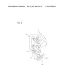
[0082] The outdoor unit 2 according to Embodiment 2 is different from the outdoor unit 2 according to Embodiment 1 in that the indication plate 36 or the indication plate 37 is provided as attention attracting means. As illustrated in FIG. 7, in the outdoor unit 2 according to Embodiment 2, the indication plate 36 or the indication plate 37 indicating the refrigerant name as the type of refrigerant is disposed on at least one of surfaces defining a hexagonal prism shape of a hexagonal sealing nut 24. Note that the hexagonal sealing nut 24 may or may not be replaced with the hexagonal sealing nut 34 illustrated in Embodiment 1.
[0083] The indication plate 36 includes an indication portion 36a indicating the refrigerant name, and a projection portion 36b extending from an end of the indication portion 36a in a direction orthogonal to the indication surface of the indication portion 36a. The projection portion 36b is provided with a C-shaped attachment portion 36c. The indication portion 36a is formed of, for example, a planar member. On a surface of the indication portion 36a which faces outward when the indication plate 36 is attached, the refrigerant name "R32" is indicated. The attachment portion 36c is fitted on the neck of a thread portion of a refrigerant charging service port 23, using the elastic force of the attachment portion 36c. By fitting the attachment portion 36c onto the neck of the thread portion of the refrigerant charging service port 23 of the gas-side pipe connecting valve 9, it is possible to hold the indication portion 36a on at least one of surfaces defining the hexagonal prism shape of the hexagonal sealing nut 24.
[0084] When forming the indication plate 36, the indication portion 36a and the projection portion 36b may be integrally formed of resin or the like, or may be separately formed of different materials and combined together. Note that the projection portion 36b is formed of an elastic material. Further, the projection portion 36b may be formed by bending one lateral end portion of the indication portion 36a as illustrated in FIG. 7(a). Alternatively, as illustrated in FIG. 7(b), the projection portion 36b may be formed by bending one lateral end portion of the indication portion 36a which lateral end portion has a size smaller than the size of the indication portion 36a in the height direction.
[0085] The indication plate 37 includes an indication portion 37a indicating the refrigerant name, and a projection portion 37b extending from an end of the indication portion 37a in a direction orthogonal to the indication surface of the indication portion 37a. The projection portion 37b is provided with a C-shaped attachment portion 37c. The indication portion 37a is formed of, for example, a planar member. On a surface of the indication portion 37a which faces outward when the indication plate 37 is attached, the refrigerant name "R32" and "a mark representing a flammable refrigerant" are indicated. The attachment portion 37c is fitted on the neck of the thread portion of the refrigerant charging service port 23, using the elastic force of the attachment portion 37c. By fitting the attachment portion 37c onto the neck of the thread portion of the refrigerant charging service port 23, it is possible to hold the indication portion 37a on at least one surface of the hexagonal-prism-shaped portion of the hexagonal sealing nut 24.
[0086] In this manner, not only the type of refrigerant, but also a mark (for example, picture, graphic, and so on) representing a flammable refrigerant, and initials may be added. Further, textual precautions may be displayed. With this indication plate 37, it is possible to provide a greater effect of attracting attention of the operator than with the indication plate 36.
[0087] Since the indication plate 36 or the indication plate 37 is provided, in the case of charging refrigerant during installation of the outdoor unit 2 or during service work thereon, the operator needs to remove the indication plate 36 before removing the hexagonal sealing nut 24 from the refrigerant charging service port 23. This is because, unless the indication plate 36 is removed, it is not possible to hold the hexagonal sealing nut 24 with a wrench. That is, each of the indication plate 36 and the indication plate 37 is one of ancillary parts that need to be operated by the operator when removing the hexagonal sealing nut 24.
[0088] As described above, according to the outdoor unit 2 of Embodiment 2, by providing an ancillary part (the indication plate 36 or the indication plate 37) that needs to be operated by the operator when removing the hexagonal sealing nut 24, it is possible to more reliably make the operator recognize the type of refrigerant used, than by using the method of simply applying a sticker or the like indicating the type of refrigerant in the vicinity of a connecting valve. This prevents the operator from charging a wrong refrigerant when performing a refrigerant charging work, and makes it possible to increase the safety. Further, this eliminates the risk of a reduction in the performance and quality of the air-conditioning apparatus A. In particular, in the case where a flammable refrigerant such as R32 and R290 is used, this provides a great effect in terms of safety, and also contributes to suppression of global warming.
Embodiment 3
[0089] FIG. 8 is an explanatory view for explaining the specifications of a pipe connecting valve of an outdoor unit 2 according to Embodiment 3 of the present invention. The following describes how the operator recognizes the type of refrigerant contained in an air-conditioning apparatus A, with reference to FIG. 8. In Embodiment 3, elements that are the same as those described in Embodiments 1 and 2 are denoted by the same reference signs, and the description will focus on the differences from Embodiments 1 and 2.
[0090] The outdoor unit 2 according to Embodiment 3 is different from the outdoor unit 2 according to Embodiment 1 in that an indication plate 38 is provided as attention attracting means. As illustrated in FIG. 8, in the outdoor unit 2 according to Embodiment 3, the indication plate 38 indicating the refrigerant name is disposed on a hexagonal-prism-shaped portion of a hexagonal sealing nut 24. Note that the hexagonal sealing nut 24 may or may not be replaced with the hexagonal sealing nut 34 illustrated in Embodiment 1.
[0091] The indication plate 38 includes an indication portion 38a indicating the refrigerant name, and a projection portion 38b extending from an end of the indication portion 38a in a direction orthogonal to the indication surface of the indication portion 38a. The projection portion 38b is provided with a ring-shaped attachment portion 38c corresponding to the hexagonal-prism-shaped portion of the hexagonal sealing nut 24. The indication portion 38a is formed of, for example, a planar member. On a surface of the indication portion 38a which faces outward when the indication plate 38 is attached, the refrigerant name "R32" is indicated. The attachment portion 38c is fitted on the hexagonal-prism-shaped portion of the hexagonal sealing nut 24, so that the projection portion 38b is attached to the hexagonal sealing nut 24.
[0092] When forming the indication plate 38, the indication portion 38a and the projection portion 38b may be integrally formed of resin, metal, or the like, or may be separately formed of different materials and combined together. Further, similar to the indication plate 37 described in Embodiment 2, not only the type of refrigerant, but also a mark representing a flammable refrigerant, and initials may be added. Further, textual precautions may be displayed.
[0093] Since the indication plate 38 is provided, in the case of charging refrigerant during installation of the outdoor unit 2 or during service work thereon, the operator needs to remove the indication plate 38 before removing the hexagonal sealing nut 24 from the refrigerant charging service port 23. This is because, unless the indication plate 38 is removed, it is not possible to hold the hexagonal sealing nut 24 with a wrench. That is, the indication plate 38 is one of ancillary parts that need to be operated by the operator when removing the hexagonal sealing nut 24.
[0094] As described above, according to the outdoor unit 2 of Embodiment 3, by providing an ancillary part (the indication plate 38) that needs to be operated by the operator when removing the hexagonal sealing nut 24, it is possible to more reliably make the operator recognize the type of refrigerant used, than by using the method of simply applying a sticker or the like indicating the type of refrigerant in the vicinity of a connecting valve. This prevents the operator from charging a wrong refrigerant when performing a refrigerant charging work, and makes it possible to increase the safety. Further, this eliminates the risk of a reduction in the performance and quality of the air-conditioning apparatus A. In particular, in the case where a flammable refrigerant such as R32 and R290 is used, this provides a great effect in terms of safety, and also contributes to suppression of global warming.
Embodiment 4
[0095] FIG. 9 is an explanatory view for explaining the specifications of a pipe connecting valve of an outdoor unit 2 according to Embodiment 4 of the present invention. The following describes how the operator recognizes the type of refrigerant contained in an air-conditioning apparatus A, with reference to FIG. 9. In Embodiment 4, elements that are the same as those described in Embodiments 1 through 3 are denoted by the same reference signs, and the description will focus on the differences from Embodiments 1 through 3.
[0096] The outdoor unit 2 according to Embodiment 4 is different from the outdoor unit 2 according to Embodiment 1 in that an indication plate 40 is provided as attention attracting means. As illustrated in FIG. 9, in the outdoor unit 2 according to Embodiment 4, a circumferential groove 39 is provided in a hexagonal-prism-shaped portion of a hexagonal sealing nut 24, and the indication plate 40 indicating the refrigerant name is disposed in the groove 39. Note that the hexagonal sealing nut 24 may or may not be replaced with the hexagonal sealing nut 34 illustrated in Embodiment 1. Further, the groove 39 does not have to be circumferential, and may be formed to have about the height that allows a projection portion 40b to be attached on at least a part of the hexagonal-prism-shaped portion of the hexagonal sealing nut 24.
[0097] The indication plate 40 includes an indication portion 40a indicating the refrigerant name, and the projection portion 40b extending from the back of the indication portion 40a in a direction orthogonal to the indication surface of the indication portion 40a. The projection portion 40b is provided with a C-shaped attachment portion 40c. The indication portion 40a is formed of, for example, a planar member. On a surface of the indication portion 40a which faces outward when the indication plate 40 is attached, the refrigerant name "R32" is indicated. The attachment portion 40c is fitted in the groove 39, using the elastic force of the attachment portion 40c. By fitting the attachment portion 40c into the groove 39, it is possible to hold the indication portion 40a on the hexagonal-prism-shaped portion of the hexagonal sealing nut 24.
[0098] When forming the indication plate 40, the indication portion 40a and the projection portion 40b may be integrally formed of resin or the like, or may be separately formed of different materials and combined together. Note that the projection portion 40b is formed of an elastic material. Further, similar to the indication plate 37 described in Embodiment 2, not only the type of refrigerant, but also a mark representing a flammable refrigerant, and initials may be added. Further, textual precautions may be displayed.
[0099] Since the indication plate 40 is provided, in the case of charging refrigerant during installation of the outdoor unit 2 or during service work thereon, the operator needs to remove the indication plate 40 before removing the hexagonal sealing nut 24 from the refrigerant charging service port 23. This is because, unless the indication plate 40 is removed, it is not possible to hold the hexagonal sealing nut 24 with a wrench. That is, the indication plate 40 is one of ancillary parts that need to be operated by the operator when removing the hexagonal sealing nut 24.
[0100] As described above, according to the outdoor unit 2 of Embodiment 4, by providing an ancillary part (the indication plate 40) that needs to be operated by the operator when removing the hexagonal sealing nut 24, it is possible to more reliably make the operator recognize the type of refrigerant used, than by using the method of simply applying a sticker or the like indicating the type of refrigerant in the vicinity of a connecting valve. This prevents the operator from charging a wrong refrigerant when performing a refrigerant charging work, and makes it possible to increase the safety. Further, this eliminates the risk of a reduction in the performance and quality of the air-conditioning apparatus A. In particular, in the case where a flammable refrigerant such as R32 and R290 is used, this provides a great effect in terms of safety, and also contributes to suppression of global warming.
Embodiment 5
[0101] FIG. 10 is an explanatory view for explaining the specifications of a pipe connecting valve of an outdoor unit 2 according to Embodiment 5 of the present invention. The following describes how the operator recognizes the type of refrigerant contained in an air-conditioning apparatus A, with reference to FIG. 10. In Embodiment 5, elements that are the same as those described in Embodiments 1 through 4 are denoted by the same reference signs, and the description will focus on the differences from Embodiments 1 through 4.
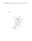
[0102] The outdoor unit 2 according to Embodiment 5 is different from the outdoor unit 2 according to Embodiment 1 in that an indication cover 41 is provided as attention attracting means. As illustrated in FIG. 10, in the outdoor unit 2 according to Embodiment 5, the indication cover 41 having a cylindrical shape and indicating the refrigerant name is disposed on a hexagonal-prism-shaped portion of a hexagonal sealing nut 24. Note that the hexagonal sealing nut 24 may or may not be replaced with the hexagonal sealing nut 34 illustrated in Embodiment 1.
[0103] The indication cover 41 indicates the refrigerant name "R32", and is configured to cover the hexagonal-prism-shaped portion of the hexagonal sealing nut 24. That is, the indication cover 41 is configured to allow the hexagonal-prism-shaped portion of the hexagonal sealing nut 24 to be inserted therein, and thus cover the outer periphery of the hexagonal-prism-shaped portion of the hexagonal sealing nut 24. In the indication cover 41, the two cylindrical ends may be open, or only one cylindrical end into which the hexagonal sealing nut 24 is inserted may be open. The indication cover 41 is preferably formed of an elastic member made of resin, metal, rubber, or the like. Further, similar to the indication plate 37 described in Embodiment 2, not only the type of refrigerant, but also a mark representing a flammable refrigerant, and initials may be added. Further, textual precautions may be displayed.
[0104] Since the indication cover 41 is provided, in the case of charging refrigerant during installation of the outdoor unit 2 or during service work thereon, the operator needs to remove the indication cover 41 before removing the hexagonal sealing nut 24 from the refrigerant charging service port 23. This is because, unless the indication cover 41 is removed, it is not possible to hold the hexagonal sealing nut 24 with a wrench. That is, the indication cover 41 is one of ancillary parts that need to be operated by the operator when removing the hexagonal sealing nut 24.
[0105] As described above, according to the outdoor unit 2 of Embodiment 5, by providing an ancillary part (the indication cover 41) that needs to be operated by the operator when removing the hexagonal sealing nut 24, it is possible to more reliably make the operator recognize the type of refrigerant used, than by using the method of simply applying a sticker or the like indicating the type of refrigerant in the vicinity of a connecting valve. This prevents the operator from charging a wrong refrigerant when performing a refrigerant charging work, and makes it possible to increase the safety. Further, this eliminates the risk of a reduction in the performance and quality of the air-conditioning apparatus A. In particular, in the case where a flammable refrigerant such as R32 and R290 is used, this provides a great effect in terms of safety, and also contributes to suppression of global warming.
Embodiment 6
[0106] FIG. 11 is an explanatory view for explaining the specifications of a pipe connecting valve of an outdoor unit 2 according to Embodiment 6 of the present invention. The following describes how the operator recognizes the type of refrigerant contained in an air-conditioning apparatus A, with reference to FIG. 11. In Embodiment 6, elements that are the same as those described in Embodiments 1 through 5 are denoted by the same reference signs, and the description will focus on the differences from Embodiments 1 through 5.
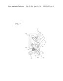
[0107] The outdoor unit 2 according to Embodiment 6 is different from the outdoor unit 2 according to Embodiment 1 in that an indication plate 42 is provided as attention attracting means. As illustrated in FIG. 11, in the outdoor unit 2 according to Embodiment 6, the indication plate 42 indicating the refrigerant name is disposed on the neck of a thread portion of a refrigerant charging service port 23. Note that the hexagonal sealing nut 24 may or may not be replaced with the hexagonal sealing nut 34 illustrated in Embodiment 1.
[0108] The indication plate 42 includes an indication portion 42a indicating the refrigerant name, and a projection portion 42b extending from an end of the indication portion 42a in such a direction that the indication surface of the indication portion 42a extends. The projection portion 42b is provided with a ring-shaped attachment portion 42c corresponding to the neck of the thread portion of the refrigerant charging service port 23. The indication portion 42a is formed of, for example, a planar member. On a surface of the indication portion 42a which faces the direction of a hexagonal sealing nut 24 when the indication plate 42 is attached, the refrigerant name "R32" is indicated. The attachment portion 42c is fitted on the neck of the thread portion of the refrigerant charging service port 23.
[0109] That is, the hexagonal sealing nut 24 is attached to the refrigerant charging service port 23, while the indication plate 42 is attached to the neck of the thread portion of the refrigerant charging service port 23. Accordingly, the hexagonal sealing nut 24 prevents the indication plate 42 from coming off. Further, the operator sees the indication portion 42a of the indication plate 42 when holding the hexagonal sealing nut 24 with a wrench.
[0110] When forming the indication plate 42, the indication portion 42a and the projection portion 42b may be integrally formed of resin, metal, or the like, or may be separately formed of different materials and combined together. Further, similar to the indication plate 37 described in Embodiment 2, not only the type of refrigerant, but also a mark representing a flammable refrigerant, and initials may be added. Further, textual precautions may be displayed.
[0111] Since the indication plate 42 is provided, in the case of charging refrigerant during installation of the outdoor unit 2 or during service work thereon, the operator sees the indication plate 42 when removing the hexagonal sealing nut 24 from the refrigerant charging service port 23. This is because the indication plate 42 is attached while being prevented by the hexagonal sealing nut 24 from coming off. Further, when attaching the charging hose 26, the indication plate 42 often needs to be removed. This is because, the charging hose 26 needs to be securely attached to the refrigerant charging service port 23. That is, the indication plate 42 is one of ancillary parts that need to be operated by the operator when removing the hexagonal sealing nut 24.
[0112] As described above, according to the outdoor unit 2 of Embodiment 6, by providing an ancillary part (the indication plate 42) that needs to be operated by the operator when removing the hexagonal sealing nut 24, it is possible to more reliably make the operator recognize the type of refrigerant used, than by using the method of simply applying a sticker or the like indicating the type of refrigerant in the vicinity of a connecting valve. This prevents the operator from charging a wrong refrigerant when performing a refrigerant charging work, and makes it possible to increase the safety. Further, this eliminates the risk of a reduction in the performance and quality of the air-conditioning apparatus A. In particular, in the case where a flammable refrigerant such as R32 and R290 is used, this provides a great effect in terms of safety, and also contributes to suppression of global warming.
Embodiment 7
[0113] FIGS. 12 through 14 are explanatory views for explaining the specifications of a pipe connecting valve of an outdoor unit 2 according to Embodiment 7 of the present invention. The following describes how the operator recognizes the type of refrigerant contained in an air-conditioning apparatus A, with reference to FIGS. 12 through 14. In Embodiment 7, elements that are the same as those described in Embodiments 1 through 6 are denoted by the same reference signs, and the description will focus on the differences from Embodiments 1 through 6.
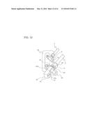
[0114] The outdoor unit 2 according to Embodiment 7 is different from the outdoor unit 2 according to Embodiment 1 in that an indication cover 43 is provided as attention attracting means. As illustrated in FIGS. 12 through 14, in the outdoor unit 2 according to Embodiment 7, the indication cover 43 is provided, which is configured such that one end thereof is attached to a base portion of a refrigerant pipe connecting port (hereinafter referred to as a refrigerant pipe connecting port 45) of the body of a gas-side pipe connecting valve 9, and such that the other end thereof detachably covers at least a part of a hexagonal-prism-shaped portion of a hexagonal sealing nut 24. Note that the hexagonal sealing nut 24 may or may not be replaced with the hexagonal sealing nut 34 illustrated in Embodiment 1.
[0115] The indication cover 43 includes an indication portion 43a indicating the refrigerant name and detachably covering the hexagonal-prism-shaped portion of the hexagonal sealing nut 24, an extension portion 43b extending from a part of the indication portion 43a to the refrigerant pipe connecting port 45, a ring-shaped attachment portion 44 that is provided at an end of the extension portion 43b and is attached to the base portion of the refrigerant pipe connecting port 45, a flexing portion 46 that flexibly couples the extension portion 43b and the attachment portion 44 to each other, and a projection 47 that is formed at a side opposite to the side at which the extension portion 43b of the indication portion 43a is formed and that abuts the hexagonal sealing nut 24 when the hexagonal-prism-shaped portion of the hexagonal sealing nut 24 is covered with the indication cover 43.
[0116] Note that the extension portion 43b, the attachment portion 44, the flexing portion 46, and the projection 47 correspond to a "holding portion" of the present invention.
[0117] As illustrated in FIGS. 12 and 13, the indication portion 43a is, for example, configured to have a surface parallel to at least two surfaces of the hexagonal-prism-shaped portion of the hexagonal sealing nut 24, and a surface parallel to the front end of the hexagonal sealing nut 24. The refrigerant name "R32" is indicated on at least one of these surfaces. In FIGS. 12 and 13, an example is illustrated in which the refrigerant name is indicated on the surface of the indication portion 43a at the near side of the paper of FIGS. 12 and 13.
[0118] The extension portion 43b connects the indication portion 43a and the attachment portion 44 to each other. The length of the extension portion 43b is about a length that extends from the refrigerant pipe connecting port 45 to the neck of the thread portion of the refrigerant charging service port 23, for example. Note that although FIGS. 12 and 13 illustrate an example in which the extension portion 43b has a shape extending from one surface of the indication portion 43a toward the refrigerant pipe connecting port 45, the extension portion 43b may have the shape of, for example, a string made of resin, fiber, metal, or the like as illustrated in FIG. 14.
[0119] The attachment portion 44 is configured to be attached to the refrigerant pipe connecting port 45 while the refrigerant pipe connecting port 45 is inserted through the ring-shaped portion thereof.
[0120] The flexing portion 46 is a hinge, and is configured to move the indication portion 43a and the extension portion 43b while the attachment portion 44 is attached to the base portion of the refrigerant pipe connecting port 45. Note that as illustrated in FIG. 14, in the case where the extension portion 43b has the shape of a string, there is no need to provide the flexing portion 46.
[0121] The projection 47 is formed so as to project toward the hexagonal sealing nut 24, at the side opposite to the side at which the extension portion 43b of the indication portion 43a is formed, that is, at a position where the projection 47 is caught by the hexagonal-prism-shaped portion of the hexagonal sealing nut 24 when removing the indication portion 43a from the hexagonal-prism-shaped portion of the hexagonal sealing nut 24. That is, with the indication portion 43a and the projection 47, the indication cover 43 fits on the hexagonal-prism-shaped portion of the hexagonal sealing nut 24, and thus covers the hexagonal sealing nut 24. Note that as illustrated in FIG. 14, in the case where the indication portion 43a has the shape of a cap, there is no need to provide the projection 47.
[0122] More specifically, once the indication cover 43 is pushed into a position where the indication cover 43 covers the hexagonal sealing nut 24, the projection 47 comes into contact with the hexagonal sealing nut 24 and is fixed at this position. When receiving a force in the direction of removal, the projection 47 is elastically deformed, so that the projection 47 comes off the hexagonal sealing nut 24. Thus, the indication cover 43 opens via the flexing portion 46 toward the side opposite to the hexagonal sealing nut 24.
[0123] When forming the indication cover 43, the indication portion 43a, the extension portion 43b, the attachment portion 44, and the projection 47 may be integrally formed of resin, metal, or the like, or may be separately formed of different materials and combined together. Note that the projection 47 is formed of an elastic material. Further, similar to the indication plate 37 described in Embodiment 2, not only the type of refrigerant, but also a mark representing a flammable refrigerant, and initials may be added. Further, textual precautions may be displayed.
[0124] Since the indication cover 43 is provided, in the case of charging refrigerant during installation of the outdoor unit 2 or during service work thereon, the operator needs to remove the indication portion 43a of the indication cover 43 before removing the hexagonal sealing nut 24 from the refrigerant charging service port 23. This is because, unless the indication portion 43a is removed, it is not possible to hold the hexagonal sealing nut 24 with a wrench. That is, the indication cover 43 is one of ancillary parts that need to be operated by the operator when removing the hexagonal sealing nut 24.
[0125] As described above, according to the outdoor unit 2 of Embodiment 7, by providing an ancillary part (the indication cover 43) that needs to be operated by the operator when removing the hexagonal sealing nut 24, it is possible to more reliably make the operator recognize the type of refrigerant used, than by using the method of simply applying a sticker or the like indicating the type of refrigerant in the vicinity of a connecting valve. This prevents the operator from charging a wrong refrigerant when performing a refrigerant charging work, and makes it possible to increase the safety. Further, this eliminates the risk of a reduction in the performance and quality of the air-conditioning apparatus A. In particular, in the case where a flammable refrigerant such as R32 and R290 is used, this provides a great effect in terms of safety, and also contributes to suppression of global warming.
Embodiment 8
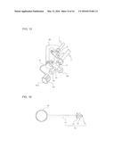
[0126] FIGS. 15 through 17 are explanatory views for explaining the specifications of a pipe connecting valve of an outdoor unit 2 according to Embodiment 8 of the present invention. The following describes how the operator recognizes the type of refrigerant contained in an air-conditioning apparatus A, with reference to FIGS. 15 through 17. In Embodiment 8, elements that are the same as those described in Embodiments 1 through 7 are denoted by the same reference signs, and the description will focus on the differences from Embodiments 1 through 7.
[0127] The outdoor unit 2 according to Embodiment 8 is different from the outdoor unit 2 according to Embodiment 1 in how the indication cover 41 described in Embodiment 5 is attached. In the following description, the indication cover 41 of Embodiment 8 is referred to as an indication cover 41A so as to be distinguished from the indication cover of Embodiment 5. As illustrated in FIG. 15, in the outdoor unit 2 according to Embodiment 8, the indication cover 41A having a cylindrical shape and indicating the refrigerant name is disposed on a hexagonal-prism-shaped portion of a hexagonal sealing nut 24, as described in Embodiment 5. Note that the hexagonal sealing nut 24 may or may not be replaced with the hexagonal sealing nut 34 illustrated in Embodiment 1.
[0128] Similar to the indication cover 41, the indication cover 41A indicates the refrigerant name "R32", and is configured to cover the hexagonal-prism-shaped portion of the hexagonal sealing nut 24. That is, the indication cover 41A is configured to allow the hexagonal-prism-shaped portion of the hexagonal sealing nut 24 to be inserted therein, and thus covers the outer periphery of the hexagonal-prism-shaped portion of the hexagonal sealing nut 24. In the indication cover 41A, the two cylindrical ends may be open, or only one cylindrical end into which the hexagonal sealing nut 24 is inserted may be open. The indication cover 41A is preferably formed of an elastic member made of resin, metal, rubber, or the like. Further similar to the indication plate 37 described in Embodiment 2, not only the type of refrigerant, but also a mark representing a flammable refrigerant, and initials may be added. Further, textual precautions may be displayed.
[0129] As for the refrigerant name "R32" indicated on the indication cover 41A, the indication "R32" is preferably engraved (hereinafter referred to as an engraved indication 80). If the engraved indication 80 is displayed on a bottom surface of the indication cover 41A, the engraved indication 80 is hard to be seen when the indication cover 41A is attached. Therefore, the engraved indication 80 is preferably displayed at a position from which the engraved indication 80 is easily seen and which is on the near side of a side surface of the indication cover 41A.
[0130] When the indication cover 41A is removed during installation work or during service work, the indication cover 41A might be lost and fail to play the role of a refrigerant identification part. In view of that, the indication cover 41A is attached to the side panel 66 via a string-shaped coupling portion 70. Thus, it is not possible to remove the indication cover 41A from the side panel 66, and therefore the indication cover 41A will be present when charging refrigerant after some years.
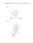
[0131] However, if the coupling portion 70 is excessively short, it becomes difficult to attach and detach the indication cover 41A. Further, if the coupling portion 70 is excessively long, the coupling portion 70 disturbs the work. In view of that, as illustrated in FIG. 16, it is preferable that the coupling portion 70 be formed integrally with the indication cover 41A, and have a length of 3 to 5 times the size (height dimension) of the indication cover 41A. Thus, the workability is not reduced. Note that the coupling portion 70 and the indication cover 41A may be formed separately. In any case, a proximal end of the coupling portion 70 only has to be coupled to the indication cover 41A.
[0132] Further, a distal end (an end not in contact with the indication cover 41A) of the coupling portion 70 is attached to the side panel 66. When attaching the coupling portion 70 to the side panel 66, the distal end of the coupling portion 70 is preferably fixed to the side panel 66 by a screw or the like so as to prevent the indication cover 41A from being removed. However, fixing of the distal end of the coupling portion 70 is not limited to fixing by a screw. For example, the distal end of the coupling portion 70 may be configured to have a shape illustrated in FIGS. 16 and 17.
[0133] A specific example of the configuration of the coupling portion 70 will be described. The coupling portion 70 includes a body portion 74 that connects between the distal end side and the proximal end side, a distal locking portion 71 having the shape of an arrow, a rib 72 that is disposed at the proximal end side (the indication cover 41A side) with respect to the distal locking portion 71 and that serves as a stopper, and a connecting portion 73 that connects the distal locking portion 71 and the rib 72 to the body portion 74. Note that the distal end of the coupling portion 70 includes the distal locking portion 71 and the rib 72. If all the elements of the coupling portion 70 are integrally formed, there is no need to provide the connecting portion 73.
[0134] The distal locking portion 71 is inserted in a hole formed in the side panel 66, and thus serves to lock the entire coupling portion 70 onto the side panel 66. The distal locking portion 71 is formed such that its diameter increases from the distal end toward the proximal end. When the distal locking portion 71 is inserted into the hole formed in the side panel 66, the distal locking portion 71 is elastically deformed by the hole. When the entire part of the increased diameter portion is inserted, the distal locking portion 71 is released from the elastic deformation, so that the proximal end portion of the distal locking portion 71 abuts the inner wall of the side panel 66. Thus, the distal locking portion 71 is locked on the side panel 66, so that the entire coupling portion 70 is attached to the side panel 66. Further, the proximal end portion of the distal locking portion 71 abuts the inner wall of the side panel 66, thereby preventing coming-off.
[0135] The rib 72 is formed in the shape of a bowl, and is located on the outer side of the side panel 66 when the distal locking portion 71 is locked on the side panel 66. More specifically, the rib 72 has a function of a suction cup, and adheres to the outer surface of the side panel 66 so as to serve as a stopper for maintaining the coupling portion 70 attached to the side surface.
[0136] The connecting portion 73 connects the distal locking portion 71 and the rib 72 to the body portion 74. The connecting portion 73 is formed in a shape that extends beyond the outer periphery of the body portion 74, and is reinforced such that the distal locking portion 71 and the rib 72 are not easily removed from the body portion 74.
[0137] The body portion 74 is deformable, and is coupled to the indication cover 41.
[0138] As described above, according to the outdoor unit 2 of Embodiment 8, by providing an ancillary part (the indication cover 41A) that needs to be operated by the operator when removing the hexagonal sealing nut 24 it is possible to more reliably make the operator recognize the type of refrigerant used, than by using the method of simply applying a sticker or the like indicating the type of refrigerant in the vicinity of a connecting valve. This prevents the operator from charging a wrong refrigerant when performing a refrigerant charging work, and makes it possible to increase the safety. Further, this eliminates the risk of a reduction in the performance and quality of the air-conditioning apparatus A. In particular, in the case where a flammable refrigerant such as R32 and R290 is used, this provides a great effect in terms of safety, and also contributes to suppression of global warming. Further, there is no risk of the indication cover 41A being lost, thereby contributing to the safety for a long period of time.
Embodiment 9
[0139] FIGS. 18 and 19 are explanatory views for explaining the specifications of a pipe connecting valve of an outdoor unit 2 according to Embodiment 9 of the present invention. The following describes how the operator recognizes the type of refrigerant contained in an air-conditioning apparatus A, with reference to FIGS. 18 and 19. In Embodiment 9, elements that are the same as those described in Embodiments 1 through 8 are denoted by the same reference signs, and the description will focus on the differences from Embodiments 1 through 8.
[0140] The outdoor unit 2 according to Embodiment 8 is different from the outdoor unit 2 according to Embodiment 1 in the configuration of the indication cover 41 illustrated in Embodiment 5. In the following description, the indication cover 41 of Embodiment 9 is referred to as an indication cover 41B so as to be distinguished from the indication cover of Embodiment 5. As illustrated in FIGS. 18 and 19, in the outdoor unit 2 according to Embodiment 8, the indication cover 41B having a cylindrical shape and indicating the refrigerant name is disposed on a hexagonal-prism-shaped portion of a hexagonal sealing nut 24, as described in Embodiment 5. Note that the hexagonal sealing nut 24 may or may not be replaced with the hexagonal sealing nut 34 illustrated in Embodiment 1.
[0141] Similar to the indication cover 41, the indication cover 41B indicates the refrigerant name "R32", and is configured to cover the hexagonal-prism-shaped portion of the hexagonal sealing nut 24. That is, the indication cover 41B is configured to allow the hexagonal-prism-shaped portion of the hexagonal sealing nut 24 to be inserted therein, and thus cover the outer periphery of the hexagonal-prism-shaped portion of the hexagonal sealing nut 24. In the indication cover 41B, the two cylindrical ends may be open, or only one cylindrical end into which the hexagonal sealing nut 24 is inserted may be open. The indication cover 41B is preferably formed of an elastic member made of resin, metal, rubber, or the like. Further, similar to the indication plate 37 described in Embodiment 2, not only the type of refrigerant, but a so a mark representing a flammable refrigerant, and initials may be added. Further, textual precautions may be displayed.
[0142] As for the refrigerant name "R32" indicated on the indication cover 41B, the indication "R32" is preferably an engraved indication 80 as in the case of the indication cover 41A. If the engraved indication 80 is displayed on a bottom surface of the indication cover 41B, the engraved indication 80 is hard to be seen when the indication cover 41B is attached. Therefore, the engraved indication 80 is preferably displayed at a position from which the engraved indication 80 is easily seen and which is on the near side of a side surface of the indication cover 41B.
[0143] The indication cover 41B is often attached in an inclined manner to the hexagonal sealing nut 24. If water droplets are condensed on the refrigerant charging service port 23, water collects in the indication cover 41B. When the water collects and remains in the indication cover 41B without being discharged, the hexagonal sealing nut 24 might corrode. In view of that, a drain hole 81 is formed in the indication cover 41B. Thus, it is possible to discharge the water collected in the indication cover 41B, and prevent the hexagonal sealing nut 24 from corroding.
[0144] However, in view of the strength of the indication cover 41B, it is more preferable to form the drain hole 81 with a cross-shaped reinforcing portion 82 therein as illustrated in FIGS. 18 and 19, than to form the drain hole 81 extending across the entire bottom surface (a surface opposite to the open surface) of the indication cover 41B. Further, as illustrated in FIG. 19, the indication cover 41B may be attached to the side panel 66 using the coupling portion 70 described in Embodiment 8.
[0145] As described above, according to the outdoor unit 2 of Embodiment 9, by providing an ancillary part (the indication cover 41B) that needs to be operated by the operator when removing the hexagonal sealing nut 24, it is possible to more reliably make the operator recognize the type of refrigerant used, than by using the method of simply applying a sticker or the like indicating the type of refrigerant in the vicinity of a connecting valve. This prevents the operator from charging a wrong refrigerant when performing a refrigerant charging work, and makes it possible to increase the safety. Further, this eliminates the risk of a reduction in the performance and quality of the air-conditioning apparatus A. In particular, in the case where a flammable refrigerant such as R32 and R290 is used, this provides a great effect in terms of safety, and also contributes to suppression of global warming. Further, there is no risk of the hexagonal sealing nut 24 corroding, thereby contributing to the safety for a long period of time.
[0146] In Embodiments 2 through 9, there is no particular description of the exterior color of the indication plate 36, the indication plate 37, the indication plate 38, the indication plate 40, the indication cover 41 (including the indication cover 41A and the indication cover 41B), the indication plate 42, and the indication cover 43. Since the display color of the refrigerant cylinder differs from refrigerant to refrigerant, the exterior color of these indication plates and indication covers is preferably the same as the color of the refrigerant cylinder for easier recognition of the type of refrigerant. For example, the display color of the refrigerant cylinder for R32 is light blue, and therefore the color of the indication plates and indication covers is preferably light blue.
REFERENCE SIGNS LIST
[0147] 1 indoor unit 2 outdoor unit 3 compressor 4 four-way valve 5 outdoor heat exchanger 6 flow rate control device 7 extension pipe 8 liquid-side pipe connecting valve 9 gas-side pipe connecting valve 10 pipe decorative cover 11 indoor heat exchanger 12 liquid-side pipe connecting joint 13 gas-side pipe connecting joint 14 driving device 15 outdoor blower motor 16 outdoor fan 17 terminal block 18 indoor blower motor 19 blower fan 20 terminal block 21 installation plate 22 VVF cable 23 refrigerant charging service port 24 hexagonal sealing nut 25 vacuum pump 26 charging hose 27 pressure gauge 28 hexagonal stem nut 29 hexagonal key 30 gas-pipe-side stem 31 hexagonal stem nut 32 liquid-pipe-side stem 33 valve 34 hexagonal sealing nut 35 indication 36 indication plate 36a indication portion 36b projection portion 36c attachment portion 37 indication plate 37a indication portion 37b projection portion 37c attachment portion 38 indication plate 38a indication portion 38b projection portion 38c attachment portion 39 groove 40 indication plate 40a indication portion 40b projection portion 40c attachment portion 41 indication cover 41A indication cover 41B indication cover 42 indication plate 42a indication portion 42b projection portion 42c attachment portion 43 indication cover 43a indication portion 43b extension portion 44 attachment portion 45 refrigerant pipe connecting port 46 flexing portion 47 projection 51 support block 52 base 53 electric component box 54 casing 55 front design panel 56 indoor driving device 57 air inlet 58 air outlet 59 screw 60 heat insulator 61 tape 62 panel 63 opening 64 fan guard 65 top plate 66 side panel 67 cable cover 68 opening 70 coupling portion 71 distal locking portion 72 rib 73 connecting portion 74 body portion 80 engraved indication 81 drain hole 82 reinforcing portion A air-conditioning apparatus
User Contributions:
Comment about this patent or add new information about this topic:

