Patent application title: FREQUENCY SYNTHESIZER
Inventors:
Andrei Viktorovich Gorevoi (Tomsk, RU)
Assignees:
ZAKRYTOE AKCIONERNO OBSHHESTVO "NAYCHNO- PROIZVODSTVENNAYA FIRMA "MICRAN"
IPC8 Class: AH03L718FI
USPC Class:
327105
Class name: Miscellaneous active electrical nonlinear devices, circuits, and systems signal converting, shaping, or generating synthesizer
Publication date: 2016-04-14
Patent application number: 20160105191
Abstract:
The output of a reference frequency generator is connected to the input
of a high-order frequency multiplier, the output of which is connected to
the input of an additional frequency multiplier and to a first input of a
frequency converter. The output of the additional frequency multiplier is
connected to the input of a frequency divider, the output of which is
connected to a reference input of a frequency-phase detector. The output
of the frequency converter is connected to the input of a frequency
divider with a variable division ratio, the output of which is connected
to another input of the frequency-phase detector. The output of the
frequency-phase detector is connected to an error signal filter, the
output of which is connected to the input of a controlled generator. A
second input of the frequency converter is connected to the output of the
controlled generator. The main technical result is an increase in the
frequency resolution and spectral purity of an output signal.Claims:
1. A frequency synthesizer, including the reference generator, whose
output is connected to the frequency multiplier, the frequency converter,
frequency divider, whose output is connected to the input of the
frequency phase detector, whose output is connected to the input of the
error signal filter, whose output is connected to the input of the
controlled generator, distinguished by the fact that the input of the
frequency multiplier is connected to the input of the additional
frequency multiplier, whose output is connected to the input of the
frequency divider, whose output is connected to the reference input of
the frequency phase detector, while the frequencies of the controlled
generator and the reference generator are related by the following
formula Fyr=NKRFor(1.+-.1/M); where: N--variable division
coefficient of the frequency divider; Fyr--controlled generator
frequency; M--multiplying coefficient of the frequency multiplier;
For--frequency of the frequency oscillator; K--multiplying
coefficient of the additional frequency multiplier; R--division
coefficient of the frequency divider.
2. The frequency synthesizer in claim 1, but with frequency dividers and frequency phase detector in a single integrated circuit.
Description:
CROSS-REFERENCE TO RELATED APPLICATION
[0001] This application is a national stage patent application of international application no. PCT/RU2014/000245 filed on Apr. 3, 2014. The earliest priority date claimed is Apr. 9, 2013.
FEDERALLY SPONSORED RESEARCH
[0002] Not Applicable
SEQUENCE LISTING OR PROGRAM
[0003] Not Applicable
BACKGROUND
[0004] This invention is related to the instrumentation, radiolocation and telecommunication fields.
[0005] There is a frequency synthesizer with digital phase lock loop (PLL) (Chenakin A., Frequency Synthesizers: Concept to Product, 2011, 152 pages), which includes the frequency phase detector, frequency divider with fractional variable coefficient of division N times, control signal filter and controlled generator.
[0006] The deficiencies of this product is a high noise level, due to PFD, and a low-frequency resolution due to low K values up to 25, which are produced in microchips and output 3-6 Hz resolution at minimal level of phase noise.
[0007] There is a single-loop synthesizer with a frequency conversion feedback (Chenakin A. A compact, agile, low-phase-noise frequency source with AM, FM and pulse modulation capabilities, 2009, 2 pages), which improves the spectral frequency of the output signal and improves the frequency resolution by replacing the frequency divider with a frequency converter and integrating a frequency multiplier and digital computing synthesizer, which currently has the best frequency resolution. The deficiencies of this device is a significant energy consumption and its dimensions.
The Nature of Invention
[0008] The main technical result of the proposed solution is an increase in frequency resolution and spectral frequency of the output signal, while avoiding a significant increase in energy consumption and device dimensions.
[0009] The main technical result is achieved by a frequency synthesizer, which includes a frequency oscillator, whose output is connected with a frequency multiplier; frequency converter, frequency divider, whose output is connected with a frequency phase detector input, whose output is connected with error signal filter input, whose output is connected to the controlled generator input. Per the proposed solution, the frequency multiplier output is connected with an additional frequency multiplier input, whose output is connected to the frequency divider input, whose output is connected to the frequency phase detector input, while the frequencies of the controlled generator and frequency oscillator are correlated by the following formula:
Fyr=NKRFor(1±1/M);
[0010] where: N--variable division coefficient of the frequency divider;
[0011] Fyr--controlled generator frequency;
[0012] M--multiplying coefficient of the frequency multiplier;
[0013] For--frequency of the frequency oscillator;
[0014] K--multiplying coefficient of the additional frequency multiplier;
[0015] R--division coefficient of the frequency divider.
[0016] Reasonably, frequency dividers and frequency phase detector shall be in a single integrated circuit.
DRAWINGS
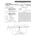
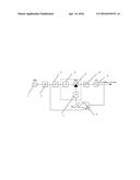
[0017] FIG. 1 shows the block diagram of the frequency synthesizer.
DETAILED DESCRIPTION
[0018] The synthesizer consists of a reference frequency generator 1, whose output is connected to the input of a high-order frequency multiplier 2, whose output is connected to the input of an additional frequency multiplier 3 and to a first input of a frequency converter 4. The output of the additional frequency multiplier 3 is connected to the input of a frequency divider 5 with fractional variable division ratio, whose output is connected to a reference input of a frequency phase detector 6. The output of the frequency converter 4 is connected to the input of a frequency divider 7 with a variable division ratio, whose output is connected to another input of the frequency phase detector 6. The output of the frequency phase detector 6 is connected to an error signal filter 8, whose output is connected to the input of the controlled generator 9. The second input of the frequency converter 4 is connected the output of the controlled generator 9. Frequency dividers 5, 7, and the frequency phase detector 6 are in the single integrated circuit.
[0019] Invention Implementation
[0020] The output signal of the frequency multiplier 2 is separated by power and fed to the input of the additional frequency multiplier 3 and to the input of the frequency converter 4. The output signal of the additional frequency multiplier 3 is connected to the input of the frequency divider 5 with a fractional variable division ratio, defined by the following formula:
N=INT+(FRAC/MOD)
where:
[0021] N--is the division ratio value of the frequency divider;
[0022] INT--is the programmable whole number of the division ratio N;
[0023] FRAC and MOD--are programmable numbers, which define the fractional part of the division ratio N.
[0024] The output signal of the frequency divider 5 is fed to the reference input of the frequency phase detector 6. The signal from the controlled generator 9 is sent to the second input of the frequency converter 4. The differential frequency signal is taken from the frequency converter output 4 and sent to the input of the frequency divider 7 with a variable division ratio, whose output signal is connected to the second input of the frequency phase detector 6. The frequency phase detector 6 generates an error signal, proportional to the phase desynchronization between its input signals. After being filtered by a filter of error signal 8, this signal is sent to the frequency control input of the controlled generator 9. The frequencies of the controlled generator 9 and the reference generator 1 are related by the following ratio:
Fyr=NKRFor(1±1/M);
while the frequency resolution equals to: ΔFyr=NKRFor/MODM
[0025] During the operational mode of the frequency phase detector 6, MK/N≦1, R<<N, which improves the frequency resolution by N/R times, when compared to the synthesizer with frequency divider with fractional variable division ratio feedback.
User Contributions:
Comment about this patent or add new information about this topic:
Images included with this patent application:
 |  |
| Similar patent applications: | |
| Date | Title |
|---|---|
| 2016-01-14 | Methods related to frequency synthesis control |
| 2016-04-14 | Frequency synthesis device and method |
| 2016-05-19 | Frequency division clock alignment using pattern selection |
| 2015-11-12 | Current synthesizer correction |
| 2016-02-18 | Radio frequency switch circuit |
| Top Inventors for class "Miscellaneous active electrical nonlinear devices, circuits, and systems" | |
| Rank | Inventor's name |
|---|---|
| 1 | Yantao Ma |
| 2 | Feng Lin |
| 3 | Ming-Chieh Huang |
| 4 | Yong-Ju Kim |
| 5 | Chan-Hong Chern |