Patent application title: Skin Based System Cooling Using Internal System Fan
Inventors:
Travis C. North (Cedar Park, TX, US)
Travis C. North (Cedar Park, TX, US)
Christopher M. Helberg (Austin, TX, US)
Christopher M. Helberg (Austin, TX, US)
Austin M. Shelnutt (Leander, TX, US)
Austin M. Shelnutt (Leander, TX, US)
Assignees:
DELL PRODUCTS L.P.
IPC8 Class: AG06F120FI
USPC Class:
36167948
Class name: Computer related housing or mounting assemblies with cooling means fan
Publication date: 2016-03-17
Patent application number: 20160077557
Abstract:
A system and method for improving the cooling of the skin of an
information handling system. More specifically, in certain embodiments,
the information handling system comprises an air moving device positioned
to generate boundary layer disruption on the external skin of the system.
In certain embodiments the air moving device is located within the
information handling system.Claims:
1. A method for cooling a system comprising: positioning an air moving
device within the system; and, generating a boundary layer disruption via
the air moving device, the boundary layer disruption being generated to
affecting an external skin of the system.
2. The method of claim 1, wherein: the air moving device is located within the system.
3. The method of claim 1, wherein: the air moving device comprises at least one jet cooling air moving device, the jet cooling air moving device being positioned to generate a high velocity low pressure air flow across the skin of the system.
4. The method of claim 1, wherein: the jet cooling air moving device is positioned in parallel with a mother board of the system.
5. The method of claim 1, wherein: the system comprises a micro porous material, the micro porous material allowing the air moving device to generate pressure oscillations which disrupt boundary layers of an external skin boundary layers from an internal air moving device.
6. The method of claim 1, wherein: the system further includes a synthetic jet and port hole to facilitate development of jet flow along the external skin.
7. A system comprising: a processor; a data bus coupled to the processor; and an air moving device, the air moving device being configured to generate a boundary layer disruption via the air moving device, the boundary layer disruption being generated to affecting an external skin of the system.
8. The system of claim 7, wherein: the air moving device is located within the system.
9. The system of claim 7, wherein: the air moving device comprises at least one jet cooling air moving device, the jet cooling air moving device being positioned to generate a high velocity low pressure air flow across the skin of the system.
10. The system of claim 7, wherein: the jet cooling air moving device is positioned in parallel with a mother board of the system.
11. The system of claim 7, wherein: the system comprises a micro porous material, the micro porous material allowing the air moving device to generate pressure oscillations which disrupt boundary layers of an external skin boundary layers from an internal air moving device.
12. The system of claim 7, wherein: the system further includes a synthetic jet and port hole to facilitate development of jet flow along the external skin.
Description:
BACKGROUND OF THE INVENTION
[0001] 1. Field of the Invention
[0002] The present invention relates to information handling systems. More specifically, embodiments of the invention relate to a skin based information handling system cooling using an internal system fan.
[0003] 2. Description of the Related Art
[0004] As the value and use of information continues to increase, individuals and businesses seek additional ways to process and store information. One option available to users is information handling systems. An information handling system generally processes, compiles, stores, and/or communicates information or data for business, personal, or other purposes thereby allowing users to take advantage of the value of the information. Because technology and information handling needs and requirements vary between different users or applications, information handling systems may also vary regarding what information is handled, how the information is handled, how much information is processed, stored, or communicated, and how quickly and efficiently the information may be processed, stored, or communicated. The variations in information handling systems allow for information handling systems to be general or configured for a specific user or specific use such as financial transaction processing, airline reservations, enterprise data storage, or global communications. In addition, information handling systems may include a variety of hardware and software components that may be configured to process, store, and communicate information and may include one or more computer systems, data storage systems, and networking systems.
[0005] One issue that relates to information handling systems, particularly mobile type information handling systems is how to best cool the information handling system. As information handling system trends continue to move toward thinner, lighter, and more powerful systems, there is a need to maximize performance while minimizing form factor. As systems continue to trend thinner and lighter, critical cooling aspects of the system have transitioned from individual components such as system on chip or memory to the system skin becoming a limiting cooling factor. For example, with one known mobile information handling system the component cooler capacity of the system supports up to 53.5 W cooling capacity while the system skin is only capable of supporting 44 W cooling capacity. Accordingly, in this example system, it is necessary to throttle system performance to keep the system within the 44 W target.
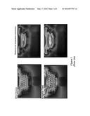
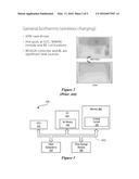
[0006] The issue of how to best cool the skin may also be more prevalent at certain locations of the system compared to other locations of the system or may be more prevalent when the system is performing certain operations compared to other operations. For example, FIG. 1, labeled Prior Art, shows an example of temperature distribution when a system is under processor stress as well as when a system is performing a graphics test. This issue of how to best cool the skin of the system is also present due to the advent of wireless charging and a move toward high power communication devices. For example, FIG. 2, labeled Prior Art, shows an example of general isotherms of a system when wireless charging is being performed.
[0007] Accordingly, it would be desirable to provide a way to improve cooling of the skin while minimizing the form factor of the system.
SUMMARY OF THE INVENTION
[0008] A system and method are disclosed for improving the cooling of the skin of an information handling system. More specifically, in certain embodiments, the information handling system comprises an air moving device positioned to generate boundary layer disruption on the external skin of the system. In certain embodiments the air moving device is located within the information handling system.
[0009] More specifically, in certain embodiments, the air moving device comprises at least one jet cooling air moving device which is positioned to generate a high velocity low pressure air flow across the skin of the system. In certain embodiments, the jet cooling air moving device is packaged in parallel with mother board allowing for unused spaced to become thermally useful. Additionally, in certain embodiments, the jet cooling air moving device has a height dimension of less than 3 mm. By so positioning the jet cooling air moving device a jet of airflow is generated along the outer surface of the system thereby disrupting the thermal boundary layer and improving cooling performance.
[0010] Additionally, in certain embodiments, the skin of the system further includes a micro porous material which allows the jet cooling air moving device to generate pressure oscillations which disrupt the boundary layers external skin boundary layers from an internal air moving device. Additionally, in certain embodiments, the system further includes a synthetic jet and port hole to facilitate development of jet flow along the external skin.
BRIEF DESCRIPTION OF THE DRAWINGS
[0011] The present invention may be better understood, and its numerous objects, features and advantages made apparent to those skilled in the art by referencing the accompanying drawings. The use of the same reference number throughout the several figures designates a like or similar element.
[0012] FIG. 1, labeled Prior Art, shows an example of temperature distribution when a system is under processor stress as well as when a system is performing a graphics test.
[0013] FIG. 2, labeled Prior Art, shows an example of general isotherms of a system when wireless charging is being performed.
[0014] FIG. 3 shows a general illustration of components of an information handling system as implemented in the system and method of the present invention.
[0015] FIG. 4 shows a diagrammatic representation of an air moving device positioned to generate boundary layer disruption on the external skin of an information handling system.
[0016] FIG. 5 shows a diagrammatic representation of a synthetic jet based air moving device.
[0017] FIG. 6 shows a diagrammatic representation of an air flow calculation set up.
[0018] FIGS. 7A and 7B show diagrammatic representations of an air flow calculation set up.
[0019] FIG. 8 shows a matrix of measurements of air flow calculations.
DETAILED DESCRIPTION
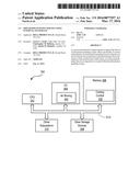
[0020] FIG. 3 is a generalized illustration of an information handling system 300 that can be used to implement the system and method of the present invention. The information handling system 300 includes a processor (e.g., central processor unit or "CPU") 302, input/output (I/O) devices 304, such as a display, a keyboard, a mouse, and associated controllers, memory 306, and various other subsystems 308. The information handling system 300 likewise includes other storage devices 310. The components of the information handling system are interconnected via one or more buses 312.
[0021] In certain embodiments, the system 300 further includes a cooling control system 330 stored in the memory 306 which includes instructions executable by the processor 302. Also, in certain embodiments the system further includes at least one air moving device 340. The air moving device 340 improves cooling of the skin (i.e., the external surface of the housing) of an information handling system 300.
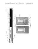
[0022] Referring to FIG. 4, a diagrammatic representation of an air moving device 340 within an information handling system 300 is shown. The air moving device 340 is positioned to generate a boundary layer disruption 410 on the external skin 420 of an information handling system is shown. The air moving device 340 improves cooling of the skin 420 (i.e., the external surface of the housing) of an information handling system 300. In certain embodiments, the air moving device 340 is positioned to generate boundary layer disruption on the external skin of the system. Also, in certain embodiments the air moving device 340 is located within the information handling system 300.
[0023] In certain embodiments, the air moving device 340 comprises at least one jet cooling air moving device which is positioned to generate a high velocity low pressure air flow across the skin of the system. A jet cooling device utilizes high velocity airflow to entrain air into the bulk air stream creating greater flow than what exits the jet exhaust directly. Typical jet airflows can approach 5 m/s but other embodiments can go beyond 8 m/s. The usefulness of the jet cooling device is that such a device allows for packaging an air mover at smaller system thickness (sub 4 mm in the Z direction) allowing for previous unused volume to be used for an air moving device. In certain embodiments, the jet cooling air moving device is packaged in parallel with the mother board 430 of the information handling system 300 thus allowing for unused spaced to become thermally useful. Additionally, in certain embodiments, the jet cooling air moving device 340 is positioned on the side of the information handling system 300 corresponding to the position of the battery 440.
[0024] Additionally, in certain embodiments, the jet cooling air moving device has a height dimension of less than 3 mm. By so positioning the jet cooling air moving device a jet of airflow is generated along the outer surface of the system thereby disrupting the thermal boundary layer and improving cooling performance. Additionally, in certain embodiments, the skin of the system further includes a micro porous material which allows the jet cooling air moving device to generate pressure oscillations which disrupt the boundary layers external skin boundary layers from an internal air moving device. A microporous material is defined as a material that has a pore diameter of as small as 2 nm (however, in certain embodiments, the pore diameter can be as large as 0.5 mm). Another way to think of this is a material that has a very small hole diameter that is difficult to see while allowing airflow through the material. This type of material is useful as it provides the form of a uniform surface while providing a cooling mechanism via airflow through the surface. Additionally, in certain embodiments, the system further includes a synthetic jet and port hole to facilitate development of jet flow along the external skin.
[0025] FIG. 5 shows a diagrammatic representation of a synthetic jet based air moving device. More specifically, using jet based air movers 510, a wall of jet flow (represented by arrows 520) is developed. This wall of jet flow provides similar performance to that of a HVAC diffuser. More specifically, this jet flow is similar to that of an HVAC diffuser in which the airstream generated is delivered along the ceiling of a building spreading the supply air over the ceiling of the building. In the present invention, the jet of airflow that is generated internal to the device is delivered over the surface of the system. In both cases the surface is cooled directly by a stream of airflow and the port hole of the system provides a similar functionality as that of a HVAC diffuser.
[0026] FIG. 6 shows a diagrammatic representation of an air flow calculation set up. More specifically, in one embodiment, the information handing system 300 includes three synthetic jet and port holes 610, 612, 614 to facilitate development of jet flow along the external skin of the information handling system 300. Each port hole is further identified by S1-S6 with local velocities V1-V6 measured at the exhaust of the port holee. For example, recent testing of an example system utilizing an external air moving device measured velocities of 2.15 m/s, s.24 m/s, 2.65 m/s, s.6 m/s, s.45 m/s and 2.2 m/s, respectively. This localized velocity allowed for a total system level airflow of 0.5 CFM which illustrated a 10C drop cooling of localized hot spots.
[0027] FIGS. 7A and 7B shows a diagrammatic representation of an air flow calculation set up. More specifically, in one embodiment, the information handing system includes a plurality of synthetic jet and port holes to facilitate development of jet flow along the external skin of the information handling system. For example, recent testing of an example system utilizing an external air moving device at 0.5CFM illustrated a 10C drop in hot spot temperature.
[0028] FIG. 8 shows a localized matrix of velocity measurements along a back surface of the system shown in FIGS. 7A and 7B. The matrix includes velocity measurements for spaces of 1.5 mm and 2 mm. Using the points identified by letters in FIG. 7B, this localized matrix represents measurements that were made at hot spot locations to determine an amount of air flowing across the hot spot locations. It can be seen from the information contained in the localized matrix that at high system air mover speeds, the system achieved over 2 m/s in localized velocities. By positioning the jets according to the hot spot locations the system significantly improves local heat transfer coefficients for the hot spots.
[0029] Based upon the data, it will be appreciated that in certain embodiments it is desirable to position the air moving device at the right side of the 10W coil to allow maximum air flow across the heated area. It will also be appreciated that it is desirable to reduce the speed of the fan because the higher the speed of the fan, the louder the noise produced by the fan.
[0030] For purposes of this disclosure, an information handling system may include any instrumentality or aggregate of instrumentalities operable to compute, classify, process, transmit, receive, retrieve, originate, switch, store, display, manifest, detect, record, reproduce, handle, or utilize any form of information, intelligence, or data for business, scientific, control, or other purposes. For example, an information handling system may be a personal computer, a network storage device, or any other suitable device and may vary in size, shape, performance, functionality, and price. The information handling system may include random access memory (RAM), one or more processing resources such as a central processing unit (CPU) or hardware or software control logic, ROM, and/or other types of nonvolatile memory. Additional components of the information handling system may include one or more disk drives, one or more network ports for communicating with external devices as well as various input and output (I/O) devices, such as a keyboard, a mouse, and a video display. The information handling system may also include one or more buses operable to transmit communications between the various hardware components.
[0031] The present invention is well adapted to attain the advantages mentioned as well as others inherent therein. While the present invention has been depicted, described, and is defined by reference to particular embodiments of the invention, such references do not imply a limitation on the invention, and no such limitation is to be inferred. The invention is capable of considerable modification, alteration, and equivalents in form and function, as will occur to those ordinarily skilled in the pertinent arts. The depicted and described embodiments are examples only, and are not exhaustive of the scope of the invention.
[0032] Consequently, the invention is intended to be limited only by the spirit and scope of the appended claims, giving full cognizance to equivalents in all respects.
User Contributions:
Comment about this patent or add new information about this topic:
Images included with this patent application:
 |  |
 |  |
| Similar patent applications: | |
| Date | Title |
|---|---|
| 2016-02-04 | Tablet computer stand |
| 2016-03-31 | Press-fit internal cable |
| 2016-05-05 | Shared esd circuitry |
| 2016-03-03 | Biased esd circuit |
| 2016-05-26 | Method and system for internal shock isolation |
| New patent applications in this class: | |
| Date | Title |
|---|---|
| 2022-05-05 | Managing airflow for computing devices |
| 2022-05-05 | Hot swappable and externally accessible fan tray and enclosure configured to house the hot swappable and externally accessible fan tray |
| 2019-05-16 | Circuit board cooling |
| 2018-01-25 | Technologies for rack cooling |
| 2018-01-25 | Technologies for rack architecture |
| New patent applications from these inventors: | |
| Date | Title |
|---|---|
| 2022-01-06 | Graphite thermal cable and method for implementing same |
| 2022-01-06 | Systems and methods for employing flexible graphite for thermal control of information handling resources |
| 2022-01-06 | Systems and methods for employing for forming and patterning flexible material |
| 2021-12-02 | System and method for mitigating liquid damage to an information handling system |
| 2021-12-02 | Management of a thermally regulated structure of an information handling system |
| Top Inventors for class "Electricity: electrical systems and devices" | |
| Rank | Inventor's name |
|---|---|
| 1 | Zheng-Heng Sun |
| 2 | Levi A. Campbell |
| 3 | Li-Ping Chen |
| 4 | Robert E. Simons |
| 5 | Richard C. Chu |