Patent application title: Cooling Control for Data Centers with Cold Aisle Containment Systems
Inventors:
Saurabh K. Shrivastava (Lemont, IL, US)
Mahmoud I. Ibrahim (Chicago, IL, US)
Bharathkrishnan Muralidharan (Tinley Park, IL, US)
Assignees:
PANDUIT CORP.
IPC8 Class: AH05K720FI
USPC Class:
36167946
Class name: For electronic systems and devices computer related housing or mounting assemblies with cooling means
Publication date: 2016-03-10
Patent application number: 20160073555
Abstract:
Embodiments of the present invention generally relate to the field of
data center cooling and energy management. In an embodiment of the
present invention, multiple PODs within a data center are controlled by a
controller via active dampers.Claims:
1. A data center, comprising: a first datacenter POD including a first
plurality of rows of cabinets where each of said first plurality of rows
of cabinets are adjacent to and share a first cold aisle, said first cold
aisle including a first temperature and a first pressure set point; a
second datacenter POD including a second plurality of rows of cabinets
where each of said second plurality of rows of cabinets are adjacent to
and share a second cold aisle, said second cold aisle including a second
temperature set point and a second pressure set point; a cold air supply
connected to both said first cold aisle and said second cold aisle, said
cold air supply providing a cold air flow having both a temperature and a
volumetric flow rate associated therewith; a first active damper
connected to and between said first cold aisle and said cold air supply;
a second active damper connected to and between said second cold aisle
and said cold air supply; a controller connected to said cold air supply,
said first active damper, and said second active damper, said controller
controlling said temperature of said cold air flow, said controller
further controlling said first active damper to partition said volumetric
flow rate to approximately achieve said first pressure set point in said
first cold aisle, said controller further controlling said second active
damper to partition said volumetric flow rate to approximately achieve
said second pressure set point in said second cold aisle.
2. The data center of claim 1, wherein said temperature of said cold air flow is controlled by said controller based on at least one of said first temperature set point and said second temperature set point.
3. The data center of claim 1, wherein said cold air supply is an under-the-floor cold air supply.
4. The data center of claim 1, wherein said cold air supply includes at least one of a supply air temperature sensor and a supply air pressure sensor.
5. The data center of claim 4, wherein at least one of said supply air temperature sensor and said supply air pressure sensor is a wireless sensor.
6. The data center of claim 1, wherein at least one of said first cold aisle and said second cold aisle includes at least one of a cabinet inlet temperature sensor and a containment pressure sensor.
7. The data center of claim 6, wherein at least one of said cabinet inlet temperature sensor and said containment pressure sensor is a wireless sensor.
8. The data center of claim 1, wherein at least one of said first active damper and said second active damper is powered using a power over Ethernet device.
Description:
CROSS-REFERENCE TO RELATED APPLICATIONS
[0001] This application claims the benefit of U.S. Provisional Patent Application No.: 62/048,423 filed on Sep. 10, 2014, which is incorporated herein by reference in its entirety.
BACKGROUND OF THE INVENTION
[0002] Data center cooling energy efficiency is critical to successful operation of modern large data centers. The cooling infrastructure can account for an average of 40% of the total data center energy consumption. Adopting methods to raise the efficiency of cooling in data centers can significantly affect the cost of running them, as well as extending their life. The current trend of deploying high heat load density cabinets in data centers necessitates the use of air containment systems. Many of the modern data centers use some kind of air containment systems to achieve high cooling energy efficiency. Air containment in simple terms provides physical separation between the supplied cool air and the cabinet exhaust hot air. This separation of cold and hot air results in cooling energy savings; however, in order to observe the maximum energy savings a proper control system for cooling units is required. Typically, the cooling units get controlled based on a coupled control scheme, wherein both the fan speed and the chilled water valve/compressor speed get controlled based on a single parameter, i.e., return or supply air temperature. These type of control schemes work well for data centers without containment systems but they may not be the best way to control cooling in data centers with containment systems.
[0003] In containment systems, the cooling units and the information technology (IT) equipment are tightly connected with each other via supply air plenum and aisle containment system. Therefore, it becomes important to not only have cold air available at a proper temperature but also have the cooling airflow in the correct amount at the IT equipment inlet. Use of coupled control schemes (i.e. supply air temperature or return air temperature) in containment system does not necessarily guarantee the above conditions and almost always results in either oversupply and/or undersupply of cooling airflow. Oversupply of cooling airflow means waste in cooling energy and cooling capacity of the data center. Undersupply of cooling airflow results in IT equipment starving for cooling airflow, which could result in unreliable operation of IT equipment.
[0004] One common aspect in these decoupled control methods is the use of supply air temperature sensor to control the temperature of the air supplied by the cooling unit. Controlling the amount of air supplied to the data center however varies significantly between the different methods. Some of the ways used to control the amount of air supplied to the data center included using underfloor pressure, server or cabinet inlet temperatures, temperature difference across a containment, and containment pressure. If a data center includes only one containment system, some of these methods may succeed in reaching optimum control. Also, if a data center includes multiple containment systems that all have exactly the same heat load and airflow demand at all times, some of these methods may again succeed in reaching optimum control. However, a typical data center almost always has more than one containment system and it is rare to have the heat load and airflow demand the same for all containment systems at all times. In these situations, the existing control schemes fall short of optimum control for cooling units and result in unwanted cooling airflow bypass, which result in waste of cooling fan energy.
SUMMARY
[0005] In an embodiment, the present invention is a data center. The data center comprises a first datacenter POD including a first plurality of rows of cabinets where each of the first plurality of rows of cabinets are adjacent to and share a first cold aisle, the first cold aisle including a first temperature and a first pressure set point; a second datacenter POD including a second plurality of rows of cabinets where each of the second plurality of rows of cabinets are adjacent to and share a second cold aisle, the second cold aisle including a second temperature set point and a second pressure set point; a cold air supply connected to both the first cold aisle and the second cold aisle, the cold air supply providing a cold air flow having both a temperature and a volumetric flow rate associated therewith; a first active damper connected to and between the first cold aisle and the cold air supply; a second active damper connected to and between the second cold aisle and the cold air supply; and a controller connected to the cold air supply, the first active damper, and the second active damper, the controller controlling the temperature of the cold air flow, the controller further controlling the first active damper to partition the volumetric flow rate to approximately achieve the first pressure set point in the first cold aisle, the controller further controlling the second active damper to partition the volumetric flow rate to approximately achieve the second pressure set point in the second cold aisle.
BRIEF DESCRIPTION OF THE DRAWINGS
[0006] FIG. 1 is a perspective view of a data center with cold aisle containment systems according to an embodiment of the present invention;
[0007] FIG. 2 is a schematic side view of the data center of FIG. 1;
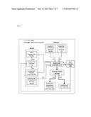
[0008] FIG. 3 is a block diagram of a cooling control system according to an embodiment of the present invention;
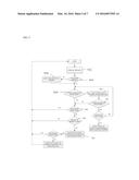
[0009] FIG. 4 is a flow chart of the cooling control system of FIG. 3;
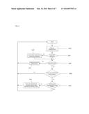
[0010] FIG. 5 is a flow chart of the cooling unit fan speed control of FIG. 4;
[0011] FIG. 6 is a flow chart of the supply air temperature set point control of FIG. 4; and
[0012] FIG. 7 is a block diagram of a cooling control system according to an alternative embodiment of the present invention.
DETAILED DESCRIPTION
[0013] One embodiment of the present invention is a cooling control solution for data centers with multiple cold aisle containment (CAC) PODs. A POD is defined as two rows of cabinets sharing a common cold aisle. The present invention includes a process that controls the amount of cooling airflow supplied by the cooling units and controls the amount of cooling airflow going into each CAC POD. The cooling control scheme closely matches the amount of air supplied by the cooling units to the amount of air required by the IT equipment while maintaining safe cabinet inlet temperatures (within threshold limits), to ensure safe and reliable operation of the IT equipment. The cooling control scheme also monitors and balances the amount of cooling airflow going into each POD.
[0014] Achieving optimum cooling control (lowest energy consumption while maintaining cabinet inlet air temperature within user defined threshold limits) in a data center with containment system can require independent control of cooling fan speed and cooling air temperature. The control scheme of the present invention decouples the control of the cooling unit; using at least one variable to control the amount of air provided by the cooling unit fan to the data center, and at least one other variable to control the temperature of the air supplied by the cooling unit.
[0015] With the use of the present invention, the data center manager/operator can reduce the amount of supplied cooling airflow and hence the cooling fan power consumption, while maintaining proper thermal environment for the IT equipment. The amount of cooling airflow saved can be used to cool additional IT equipment heat load (reclaim lost cooling capacity) that gets commissioned in future and hence helps in extending the life of the data center. The reduction in supplied cooling airflow also optimizes the cooling capacity usage by increasing the return air temperature to the cooling units.
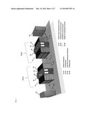
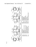
[0016] FIG. 1 is an isometric view of a data center with two CAC PODs for an embodiment of the present invention, which includes cabinet enclosures 1a-1d that house IT equipment 2a-2d with cold aisle containment enclosures 3a-3b deployed for two separate PODs. The data center is cooled using two perimeter cooling units 4a-4b. Cabinet inlet temperature sensors 5a-5b are installed at the intake of each cabinet enclosure 1a-1d. Containment pressure sensors 6a-6b are installed in each cold aisle containment enclosure 3a-3b. The raised-floor plenum in the data center has underfloor pressure sensors 7 and supply air temperature sensors 8a-8b installed. FIG. 2 provides additional details of the data center described in FIG. 1. In FIG. 2, each of the two PODs described previously have a combination of active damper tiles 9a-9b and perforated tiles 10a-10b. The IT equipment 2a-2d are cooled by the cold supply air 11a-11b that is flooded into the underfloor plenum, which then enters each POD through its associated active damper tiles 9a-9b and perforated tiles 10a-10b. Cold inlet air flow 12a-12d enters the IT equipment 2a-2d to cool the IT equipment components and returns to the data center room air as hot exhaust air 13a-13d. The hot return air 14a-14b is drawn by the cooling unit fans 15a-15b through the cooling unit 4a-4b to be cooled once again and the cycle continues.
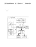
[0017] FIG. 3 is a block diagram of an embodiment of the present invention and its different components. The present invention includes an active CAC controller 17 which receives information from all the sensors deployed in the data center; cabinet inlet temperature sensors 5a-5d, containment pressure sensors 6a-6b, underfloor pressure sensors 7, and supply air temperature sensors 8a-8b as well as a system for receiving information from the active damper tiles 9a-9b on their position. Active CAC controller 17 interacts with the cooling units' fans 15a-15b and cooling units chilled water valves 16a-16b through the cooling units' 4a-4b and it interacts with a user interface 18 which allows the user to view all the data received by the active CAC controller 17 and input the desired set points for the different variables. The figure also details which specific sensor measurement inputs are used to control the active damper tiles 9a-9b, cooling units fans 15a-15b and cooling units chilled water valves 16a-16b. Input 1(i) from both supply air temperature sensors 8a-8b and cabinet inlet temperature sensors 5a-5d is used to control the cooling units chilled water valves 16a-16b opening through the output signal 1(o). Input 2(i) from the underfloor pressure sensors 7 are used to control the cooling unit fans 15a-15b speeds through the output signal 2(o). Input 3(i) from the containment pressure sensors 6a-6b is used to control the active damper tiles 9a-9b openings through the output signal 3(o).
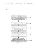
[0018] FIG. 4 details the flow of an embodiment of the invented process. In step S2, the deployed sensors are constantly measuring different variables within the data center. In step S4, providing the information collected in step S2 to the active CAC controller 17 and the user interface 18. In Step S6, the active CAC controller 17 modulates local active damper tiles 9a-9b based on local POD containment pressure sensor reading 6a-6b and POD differential pressure set point defined in user interface 18. In Step S8, the active CAC controller 17 modulates cooling units' fans 15a-15b speed based on underfloor pressure sensor reading 7 and underfloor pressure set point defined in user interface 18. With airflow balanced between all PODs in the data center and the underfloor pressure set point satisfied, in step S10 the active CAC controller 17 modulates chilled water valve 16a-16b opening based on supply air temperature sensor reading 8a-8b and supply air temperature set point defined in user interface 18.
[0019] Using the above described process, airflow is matched in each CAC POD based on the IT equipment 2a-2d airflow demand in the respective POD to the air supplied by the cooling unit fans 15a-15b which ensures that minimum to none of the air supplied is wasted. This helps achieve the optimum control of the cooling unit fans 15a-15b which in turn reduces their energy consumption. In addition to energy savings, saving the amount of air flow supplied by the cooling unit fans 15a-15b also optimizes the cooling capacity usage of the cooling units 4a-4b, allowing to extend the life of the data center and enabling the use of the full designed capacity of the cooling units 4a-4b.
[0020] FIG. 5 details the flow chart for cooling unit fans 15a-15b speed control. In step S12, containment pressure sensor 6a-6b measurements, and underfloor pressure sensor 7 measurements are reported to the active CAC controller 17. In Step 14, the active CAC controller 17 checks if any of the pressure sensors are not working If a pressure sensor isn't working, an alarm is sent to the user interface 18 to report which sensor is not working in step S16. In step S18, the active CAC controller 17 checks if the underfloor pressure sensor 7 measurements match the underfloor pressure set point defined in user interface 18. If not, in step S20 a proportional integral control loop is used to control the cooling unit fans 15a-15b to maintain the underfloor pressure set point. If the underfloor pressure set point is satisfied in step S22, the active CAC controller 17 checks if all containment pressure sensor 6a-6b measurements match the containment pressure set point defined in user interface 18 in step S24. If the containment pressure sensor 6a-6b measurements do not match the set point in step S24, the active CAC controller 17 checks if the active damper tiles 9a-9b associated with the cold aisle containment enclosure 3a-3b that has a mismatch in pressure is at a 100% or 0% opening in step S26; if so, in step S28, active CAC controller 17 overrides the initial underfloor pressure set-point condition and controls the cooling unit fans 15a-15b speed based on the containment pressure sensor 6a-6b to maintain its set point.
[0021] FIG. 6 details the flow chart for the supply air temperature set point control. In step S42, all supply temperature sensors 8a-8b measurements, and cabinet inlet temperature sensor 5a-5d measurements are reported to the active CAC controller 17. In step S44, the active CAC controller 17 checks if any of the temperature sensors are not working. If a temperature sensor isn't working, an alarm is sent to the user interface 18 in step S45 to report which sensor is not working. In S46 the active CAC controller 17 checks if a POD door is open. If so, an alarm is sent to the user interface 18 in step S47 to report which POD door is open and active controller 17 does not make any changes. If no POD door is open, the active CAC controller 17 checks if the supply air temperature sensor 7 measurement is within range of the supply air temperature set point in step S48. If not within range, the active CAC controller 17 does not make any changes, to wait for the cooling units chilled water valve 16a-16b to regulate based on the supply air temperature set point. If within range, in step S50 the active CAC controller 17 checks if all cabinet inlet temperature sensor 5a-5d measurements are within range of the cabinet inlet temperature set point. If yes, the active CAC controller 17 does not make any changes. If no, in step S51 active CAC controller 17 changes the supply air temperature set point defined in the user interface 18 by a delta value defined in the user interface 18.
[0022] In an another embodiment according to the present invention, the cooling units 4a-4b illustrated in FIG. 1 and FIG. 2 can be replaced with large air handling units that are physically located outside of the data center. However, cold air supply to the data center and warm air exhaust from the data center are in a similar fashion as depicted in FIG. 1 and FIG. 2.
[0023] In an another embodiment according to the present invention, the cooling units 4a-4b illustrated in FIG. 1 and FIG. 2 can be direct expansion (DX) cooling units that utilize a compressor for cooling instead of the chilled water supply. In this case, the cooling capacity is regulated by a compressor speed instead of a chilled water valve opening.
[0024] In an another embodiment according to the present invention, the cooling units 4a-4b illustrated in FIG. 1 and FIG. 2 can be equipped with air-side economization and/or evaporative cooling capability. In this case, the cooling capacity is regulated using supply air set point temperature and outside ambient air condition.
[0025] In an another embodiment according to the present invention, the active damper tiles 9a-9b are controlled through a damper tile controller 19 instead of the active CAC controller 17, based on a user specified set point through the user interface 18. All other aspects of the present invention remain the same. FIG. 7 is a block diagram of the present invention in the separate described embodiment.
[0026] Note that while this invention has been described in terms of several embodiments, these embodiments are non-limiting (regardless of whether they have been labeled as exemplary or not), and there are alterations, permutations, and equivalents, which fall within the scope of this invention. Additionally, the described embodiments should not be interpreted as mutually exclusive, and should instead be understood as potentially combinable if such combinations are permissive. It should also be noted that there are many alternative ways of implementing the methods and apparatuses of the present invention. It is therefore intended that claims that may follow be interpreted as including all such alterations, permutations, and equivalents as fall within the true spirit and scope of the present invention.
User Contributions:
Comment about this patent or add new information about this topic:
| People who visited this patent also read: | |
| Patent application number | Title |
|---|---|
| 20210351198 | SEMICONDUCTOR DEVICE AND MANUFACTURING METHOD OF SEMICONDUCTOR DEVICE |
| 20210351197 | Methods Of Forming An Array Of Elevationally-Extending Strings Of Memory Cells, Methods Of Forming Polysilicon, Elevationally-Extending Strings Of Memory Cells Individually Comprising A Programmable Charge Storage Transistor, And Electronic Components Comprising Polysilicon |
| 20210351196 | SEMICONDUCTOR MEMORY STRUCTURE AND MANUFACTURING METHOD THEREOF |
| 20210351195 | SEMICONDUCTOR DEVICE AND METHOD OF MANUFACTURING |
| 20210351194 | MANUFACTURING METHOD FOR MEMORY STRUCTURE |
Images included with this patent application:
 |  |
 |  |
 |  |
 |
| Similar patent applications: | |
| Date | Title |
|---|---|
| 2016-01-14 | Active-control resonant ignition system |
| 2016-01-14 | Cooling mechanism for data center |
| 2016-03-03 | Smart junction box for photovoltaic systems |
| 2015-12-24 | Uncontrolled alternating-current demagnetiser |
| 2016-05-05 | Double-angled faceplate for air flow system |
| New patent applications in this class: | |
| Date | Title |
|---|---|
| 2022-05-05 | Adjustable venting ratio mechanism for information handling system |
| 2017-08-17 | Modular data center |
| 2017-08-17 | Heat venting mechanism |
| 2017-08-17 | Protective case for a computer and method for manufacturing such a case |
| 2016-12-29 | Underwater container cooling via external heat exchanger |
| New patent applications from these inventors: | |
| Date | Title |
|---|---|
| 2015-03-05 | Thermal capacity management |
| 2013-08-08 | Computational fluid dynamics systems and methods of use thereof |
| Top Inventors for class "Electricity: electrical systems and devices" | |
| Rank | Inventor's name |
|---|---|
| 1 | Zheng-Heng Sun |
| 2 | Levi A. Campbell |
| 3 | Li-Ping Chen |
| 4 | Robert E. Simons |
| 5 | Richard C. Chu |