Patent application title: PV STAX - MULTI-FUNCTION JUNCTION MF/J SYSTEM
Inventors:
Chuck Mccune (Albuquerque, NM, US)
IPC8 Class: AH05K702FI
USPC Class:
361728
Class name: Housing or mounting assemblies with diverse electrical components for electronic systems and devices module
Publication date: 2016-03-10
Patent application number: 20160073533
Abstract:
A system to provide a multi-function connection capability to contain and
provide for stacking, mounting self-registering Multi-Function Junction
(MF/J) boxes that contain a multiplicity of control electronics and can
be stacked, removed, replaced, and/or upgraded with a minimal of steps or
connection processes in order to simplify methods and conserve on or add
value, capabilities to materials and electrical/mechanical equipment. The
system can be engaged or utilized by any EMS/First Responder/Service
Technician, authorized personnel in any field, Contractor, manufacturer,
BOS integrator and any assembler of systems that require a multiplicity
of interfacing devices to be in proximity, connection or contact to each
other.Claims:
1. A system to provide for a rapid connect/disconnect of devices to a PV
Module or junction box of any type comprised of a Multi-Function/Junction
box (MF/J), enclosure, cover or connector, designed to couple and match
factory standard or customized junction boxes and allows for rapid change
out, removal and replacement, customization, for one or more electrical,
mechanical, transmitting and receiving devices, microprocessors and
controllers that relay and/or switch on and off the source or line supply
of all potential hazardous equipment or energized parts or conveyances,
or to connect inverters, rectifiers, electrical controls, DC-DC
converters, GPS systems, line conditioners and to reduce the
install/connection time, number of box fastenings, number of cable
connections for solar PV technicians/installers, electrical and
mechanical authorized personnel and provide a plug and receptacle
connection or any other type of rapid connect/disconnect for modular
assemblies or individual devices configured for stackable mounting or
matching on any junction box or enclosure, secured by configuration and
fasteners of any type to provide proper registration and water proofing
and to prevent unintended disconnect, misalignment, or dis-mount.
2. The system of claim 1, additionally comprising module level control electronics to by-pass one or more PV modules in a string or array and to provide output, power or flow data for a multiplicity of uses and applications.
3. The system of claim 1, additionally comprising A base MF/J box on a PV Module containing PV Stop module level control electronics to receive a stacked PV DC output MF/J box with leads for connection in the PV string or array.
4. The system of claim 1, additionally comprising A base MF/J box with a stacked PV Stop module level control electronics configuration within, mounted on a standard PV Module J-Box.
5. The system of claim 1, additionally comprising A MF/J box mounted on a base MF/J box, which contains a DC to DC inverter with Maximum Power Point Tracking electronics.
6. The system of claim 1, additionally comprising A MF/J box mounted on a base MF/J box that contains micro inverter electronics capable of inverting/conditioning power, and converting any DC voltage from one or more PV Modules per Micro-Inverter, with leads out to AC cabling.
7. The system of claim 1, additionally comprising A MF/J box with connection or receptacle to receive connection or plug, both with any number or shape or configuration of plugs and receptacles, both with or without grounding conductor, from another MF/J box to be stacked
8. The system of claim 1, additionally comprising A MF/J box that contains diodes
9. The system of claim 1, additionally comprising A MF/J box that contains heat sinks of any material and/or thermo electric devices and/or EMF shielding.
10. The system of claim 1, additionally comprising MF/J box that contains switches, relays, transformers, transceivers, power semiconductors, fuses, circuit breakers to control any equipment, electrical circuit, gas/air, vehicle, battery, generator, PV Modules, PV Arrays, wind turbine, or any other power or energy system.
11. The system of claim 1, additionally comprising A MF/J box that contains ceramics, thermally conductive insulation, non-conductive electrical insulation, cubic boron nitride, glass, or other thermally conductive material.
12. The system of claim 1, additionally comprising A MF/J box that has attached or contains a transceiver antennae
13. The system of claim 1, additionally comprising any MF/J box containing any electronics having Electro Magnetic Field Shielding to prevent RF interference.
14. The system of claim 1, additionally comprising any MF/J box containing devices that send and receive data, report/locate hazards/safety systems, components inventory and personnel, control command protocols, signals etc., generated by Arduino, Raspberry PI, Zigbee or other similarly capable micro controller platform via software, hardware, wireless, wired, Wi-Fi, Bluetooth, telecom, RF, RFID, IR voice command, WAN, LAN, GPS, smartphone, GSM, CMDA Tablet, Computer or any other signal, direct signal or electrical connection or any other means of transmission/communication, connected through or directly to the PV Stop Potential Voltage and Hazard Stop system control panel or to any other control panel within acceptable industry and safety standards and certifications.
15. The system of claim 1, additionally comprising any means of secure mechanical attachment of components via screws, bolts, detents, clips, male to female components, friction fit, cams, or any other means to satisfy the intent of, or comply with electrical and mechanical codes and standards as they pertain to secure fastening.
Description:
CROSS-REFERENCE TO RELATED APPLICATIONS
[0001] This application relates to U.S. Provisional Patent Application Ser. No. 61/778,048 entitled Solar PV Safety Switch and Status Indicator System" filed on Mar. 12, 2013 and U.S. Provisional Patent Application Ser. No. 61/819,640 entitled PV Stop Potential Voltage and Hazard Stop System" filed on May 5, 2013, and U.S. Non-Provisional patent application Ser. No. 14/204,395 entitled PV Stop Potential Voltage and Hazard Stop System" filed on Mar. 11, 2014, and the specifications thereof are incorporated herein by reference.
STATEMENT REGARDING FEDERALLY SPONSORED RESEARCH OR DEVELOPMENT
[0002] Not Applicable
INCORPORATION BY REFERENCE OF MATERIAL SUBMITTED ON COMPACT DISC
[0003] Not Applicable
COPYRIGHTED MATERIAL
[0004] ©Chuck McCune. A portion of the disclosure of this patent document contains material that is subject to copyright protection. The owner has no objection to the facsimile reproduction by anyone of the patent document or the patent disclosure, as it appears in the Patent and Trademark Office patent file or records, but otherwise reserves all copyrights whatsoever.
BACKGROUND OF THE INVENTION
[0005] 1. Field of the Invention (Technical Field)
[0006] The present invention relates to devices and methods for manually or automatically controlling assemblies of devices through electronic and electro-mechanical means, to shut down, restart, modify input/output, invert, rectify, optimize, enhance safety, provide format matching of device interlocking and connection interfaces for electro-mechanical function, water proofing, electrical connection junctions, coupling of devices, coupling of industry standard devices by existing and future add-on equipment/devices, rapid plug/unplug (plug and play) devices in field installations and factory parts/device assemblies of power, liquids, or gases to buildings or facilities in case of emergencies, for adding or removing ganged assemblies and equipment, reconfiguration, maintenance and service and for manual or automated control in other situations.
[0007] 2. Background Art
[0008] The present invention relates to the Solar PV Panel, the Solar electricity industry, Electrical contracting, First Responder Fire/EMS services, Solar PV service technicians, and electrical and fire safety, manufacturing, automation, robotic, conveyor system, public or private utility, wind turbine, mechanical contracting, gas, fuel process piping of air, gas, chemical, any material, any system that would benefit from a fast means of connection for safety switching and safety control electro-mechanical devices or any system that could benefit by a secure fastening, rapid coupling/stacking system for adding micro inverters, Maximum Power Point Tracking (MPPT), Dc to DC converters, optimizers, individual controllers and data logging of equipment and in particular module level control electronics for Solar PV Modules, concentrated Solar PV and Energy Storage/utilization systems.
BRIEF SUMMARY OF THE INVENTION
[0009] Objects, advantages and novel features, and further scope of applicability of the present invention will be set forth in part in the detailed description to follow, taken in conjunction with the accompanying FIGS. 1-5, and in part will become apparent to those skilled in the art upon examination of the following, or may be learned by practice of the invention. The objects and advantages of the invention may be realized and attained by means of the instrumentalities and combinations particularly pointed out in the appended claims.
[0010] The present invention provides a system of stackable self-registering, water proof J-box sleeves covers and MF/J boxes to stack or add on a multiplicity of devices and enclosures to an electrical junction box or a MF/J box as described and claimed in the invention.
[0011] The inventive device or system provides a mean to add into the MF/J box enclosures, any number of electrical, electro-mechanical or other control devices to provide for modularity or plug and play rapid installation or removal/replacement, upgrading, assembly and disassembly of stacked MF/J boxes and the enclosed devices.
[0012] The inventive device or system provides for a multiplicity of connectors, contacts, leads, wiring harnesses, and varying configurations of electro-mechanical devices.
[0013] The inventive device or system provides for the control of the devices within the MF/J boxes through a central control panel such as PV Stop, Fire, and Alarm or other control and command generating systems for electrical and mechanical devices.
BRIEF DESCRIPTION OF THE SEVERAL VIEWS OF THE DRAWINGS
[0014] The accompanying drawings FIGS. 1-5 in the attachment, which are incorporated into and form a part of the specification, illustrate one or more embodiments of the present invention and, together with the description, serve to explain the principles of the invention. The drawings are only for the purpose of illustrating one or more preferred embodiments of the invention and are not to be construed as limiting the invention. In the drawings:
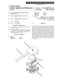
[0015] 1. PV Stax Multi-Function/Junction Base
[0016] 2. Locking Female Clip Receiver for Male clip (4)
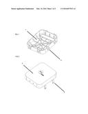
[0017] 3. PV Stax Multi-Function/Junction Cover
[0018] 4. Locking Male Clip
[0019] 5. PV Stax Multi-Function/Junction Cover with Outlet Receptacle
[0020] 6. PV Stax Multi-Function/Junction Outlet Receptacle
[0021] 7. PV Stax Multi-Function/Junction Micro-Inverter or DC to DC Converter
[0022] 8. PV Stax Multi-Function/Junction Micro-Inverter AC Leads
[0023] 9. DC Leads
[0024] 10. PV Stax Multi-Function/Junction Micro-Inverter or DC to DC Converter Male Plug
[0025] FIG. 1 is a schematic drawing of a PV Stax Multi-Function/Junction Base depicting the MF/J base box 1, configured with Locking Female Clip Receiver 2.
[0026] FIG. 2 is a schematic drawing of PV Stax Multi-Function/Junction Cover 3, configured with Locking Male Clip 4.
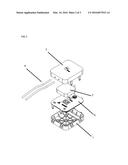
[0027] FIG. 3 is a schematic drawing of an exploded assembly of multiple possible configurations of PV Stax Multi-Function/Junction MF/J System Components depicting a PV Stax Multi-Function/Junction Cover 3, with DC Leads 9, MF/J Micro inverter or DC to DC Converter 7, a PV Stax Multi-Function/Junction Cover 5, with MF/J Outlet Receptacle 6, and a MF/J Base 1.
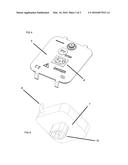
[0028] FIG. 4 is a schematic drawing depicting a PV Stax Multi-Function/Junction MF/J Cover 5, with a MF/J Outlet Receptacle 6.
[0029] FIG. 5 is a schematic drawing depicting a PV Stax Multi-Function/Junction Micro-Inverter 7, with AC Leads 8, and MF/J Male Plug 10.
DETAILED DESCRIPTION OF THE INVENTION
[0030] As depicted in FIGS. 1-5 A system to provide a multi-function connection capability to contain and provide for stacking, mounting self-registering Multi-Function Junction (MF/J) boxes that contain a multiplicity of control electronics and can be stacked, removed, replaced, and/or upgraded with a minimal of steps or connection processes in order to simplify methods and conserve on or add value, capabilities to materials and electrical/mechanical equipment. The system can be engaged or utilized by any EMS/First Responder/Service Technician, authorized personnel in any field, Contractor, manufacturer, BOS integrator and any assembler of systems that require a multiplicity of interfacing devices to be in proximity, connection or contact to each other, including Standard Electrical Boxes and enclosures, DC to DC Converters, Micro-Inverters, Module Level Control Electronics, Safety Systems, Monitoring Systems, Rapid Shutdown Systems, Micro Processors and power Semi Conductors. The invention is further described in the documents attached hereto, PV Stax Multi-Function Junction (MF/J) box Drawings pages 1/3, 2/3, 3/3.
Industrial, Residential and Commercial Applicability
[0031] The invention is further illustrated by the following non-limiting examples.
Example 1
[0032] Standard PV J box or MF/J Base box mounted on a PV Module fitted with a MF/J box, containing Diodes, with stackable add on that contains Module Level Control Electronics.
Example 2
[0033] Standard MF/J Module Base J box mounted on a PV Module fitted with a MF/J box add on that contains a DC to DC converter.
Example 3
[0034] Standard MF/J Module J box mounted on a PV Module fitted with a MF/J box add on that contains a Micro Inverter.
Example 4
[0035] Standard MF/J Module Base J box mounted on a PV Module fitted with a MF/J box add on fitted with connections, Diodes and DC leads.
Example 5
[0036] Standard MF/J Module Base J box mounted on an electrical enclosure or utility box of any standard fitted with a MF/J box add on fitted with connections, Diodes and DC leads or AC leads.
User Contributions:
Comment about this patent or add new information about this topic:
Images included with this patent application:
 |  |
 |  |
| Similar patent applications: | |
| Date | Title |
|---|---|
| 2016-05-12 | Cooled printed circuit with multi-layer structure and low dielectric losses |
| 2016-04-07 | Modular information technology (it) rack and air flow system |
| 2016-04-21 | Improvements in and relating to antenna systems |
| 2016-05-19 | Information handling system multi-purpose connector guide pin structure |
| 2016-05-19 | Information handling system multi-purpose connector guide pin structure |
| New patent applications in this class: | |
| Date | Title |
|---|---|
| 2019-05-16 | Electronic device with seal member |
| 2019-05-16 | Electronic device module |
| 2016-07-14 | Display module |
| 2016-06-16 | Power semiconductor module and power conversion device |
| 2016-06-02 | High-frequency module |
| New patent applications from these inventors: | |
| Date | Title |
|---|---|
| 2015-12-24 | Pv stop potential voltage and hazard stop system |
| 2012-03-15 | Building structure |
| Top Inventors for class "Electricity: electrical systems and devices" | |
| Rank | Inventor's name |
|---|---|
| 1 | Zheng-Heng Sun |
| 2 | Levi A. Campbell |
| 3 | Li-Ping Chen |
| 4 | Robert E. Simons |
| 5 | Richard C. Chu |