Patent application title: Interlock Detector with Self-Diagnosis Function for an Interlock Circuit, and Method for the Self-Diagnosis of the Interlock Detector
Inventors:
Thomas Schaedlich (Kornwestheim, DE)
IPC8 Class: AG01R3128FI
USPC Class:
3247503
Class name: Fault detecting in electric circuits and of electric components of individual circuit component or element built-in test circuit
Publication date: 2015-11-19
Patent application number: 20150331041
Abstract:
The interlock detector includes a first input, wherein a first output
signal from an interlock generator is applied to the first input. The
interlock detector further includes a second output which is configured
to provide a microprocessor with a second output signal. The interlock
detector further includes a differential amplifier that includes a second
input, a third input, and a third output, wherein the second input and
the third input are connected to the first input. The interlock detector
further includes a comparator circuit that includes a fourth input and a
fourth output, wherein the fourth input is connected to the third output,
the fourth output is connected to the second output, and the fourth input
is positioned between the comparator circuit and the differential
amplifier.Claims:
1. An interlock detector comprising: a first input, wherein a first
output signal from an interlock generator is applied to the first input;
a second output configured to provide a microprocessor with a second
output signal; a differential amplifier that includes a second input, a
third input, and a third output, wherein the second input and the third
input are connected to the first input; a comparator circuit that
includes a fourth input and a fourth output, wherein the fourth input is
connected to the third output, the fourth output is connected to the
second output, and the fourth input is positioned between the comparator
circuit and the differential amplifier; a fifth input, wherein a
diagnosis signal is applied to the fifth input and the fifth input is
connected to at least one of (i) the fourth input and (ii) one of the
second input or the third input, wherein the second input and the third
input are positioned between the first input and the differential
amplifier.
2. The interlock detector as claimed in claim 1, further comprising: a plurality of fifth inputs, two of the plurality of fifth inputs are connected to the second input or the third input of the differential amplifier and a third of the plurality of fifth inputs is connected to the first input via the second input or the third input of the differential amplifier, and the remaining of the plurality of fifth inputs are connected to the fourth input.
3. The interlock detector as claimed in claim 1, wherein a connection between the fourth input and the third output is interrupted via an additional switching means and configured to diagnose the comparator circuit.
4. The interlock detector as claimed in claim 3, wherein the additional switching means is downstream of the third output and upstream of the connection between the fifth input (44) and the fourth input, wherein the fifth input is connected to the fourth input and the third output.
5. The interlock detector as claimed in claim 1, wherein each of electrical connection paths between the fifth input and at least one of the third input and the second input and the third input are provided with at least one switching means.
6. An interlock detector system comprising: an interlock circuit having an interlock circuit input; an interlock generator having an interlock generator output, wherein the interlock circuit input is connected to the interlock generator; a microprocessor, wherein the interlock generator output is connected to the processor; and an interlock detector, the interlock detector includes: a first input, wherein a first output signal from the interlock generator is applied to the first input; a second output configured to provide the microprocessor with a second output signal; a differential amplifier that includes a second input, a third input, and a third output, wherein the second input and the third input are connected to the first input; a comparator circuit that includes a fourth input and a fourth output, wherein the fourth input is connected to the third output, the fourth output is connected to the second output, and the fourth input is positioned between the comparator circuit and the differential amplifier; a fifth input, wherein a diagnosis signal is applied to the fifth input and the fifth input is connected to at least one of (i) the fourth input and (ii) one of the second input or the third input, wherein the second input and the third input are positioned between the first input and the differential amplifier, wherein the interlock generator output is connected to the microprocessor to evaluate output signals from the interlock detector and the microprocessor is connected to the fifth input to provide a signal for diagnosing the interlock detector.
7. The interlock detector system as claimed in claim 6, wherein the microprocessor is designed to directly generate the diagnosis signals for the interlock detector, or the diagnosis signals each being able to be generated via pulse width modulation signals and a respective low-pass filter between the microprocessor and the fifth input.
8. The interlock detector system as claimed in claim 6, further comprising at least one switching means positioned between the first input and the interlock generator.
9. A method for self-diagnosis of an interlock detector system, the method comprising: disconnecting an interlock detector from an interlock circuit by opening at least one switching means; generating a diagnosis signal for the interlock detector by a microprocessor; providing the diagnosis signal, via a fifth input to at least one a fourth input and at least one of second input and a third input; evaluating an output signal from the interlock detector in the microprocessor, wherein the interlock detector system includes: the interlock circuit; an interlock generator; the microprocessor; and the interlock detector, the interlock detector includes: a first input, wherein a first output signal from the interlock generator is applied to the first input; a second output configured to provide the microprocessor with a second output signal; a differential amplifier that includes the second input, the third input, and a third output, wherein the second input and the third input are connected to the first input; a comparator circuit that includes the fourth input and a fourth output, wherein the fourth input is connected to the third output, the fourth output is connected to the second output; and the fifth input is connected to at least one of (i) the fourth input and (ii) one of the second input or the third input, wherein the second input and the third input are positioned between the first input and the differential amplifier.
10. The method as claimed in claim 9, further comprising: disconnecting the comparator circuit from the differential amplifier.
11. The interlock detector as claimed in claim 1, wherein the interlock detector is comprised by a battery.
12. The interlock detector as claimed in claim 11, wherein the battery is comprised by a motor vehicle.
Description:
[0001] The present invention relates to an interlock detector for an
interlock circuit, which interlock detector is implemented in a battery
control device and enables a functional test/diagnosis of itself even if
the interlock circuit is interrupted and without the application of
external (generator) signals.
PRIOR ART
[0002] DE 10 2010 031 456 discloses a method for the safety-related disconnection of an electrical network, in which use is made of an interlock circuit (also called safety line loop, interlock or pilot line), the interruption of which disconnects an electrical energy source belonging to the electrical network or decouples it from the electrical network if there is a fear of danger to persons by live parts.
[0003] An interlock circuit which is in the form of a signal loop is therefore used in electrical networks, for example in vehicles, having a nominal voltage which exceeds 60 volts. The so-called interlock signal is generally generated using a so-called interlock generator in an energy source (for example in a battery) which supplies the electrical network with power. The signal is passed through all connectors of the electrical network and all components connected to the network, that is to say via passive and/or active so-called interlock participants. In this case, the system is configured in such a manner that, when a plug-in connection or a cover which prevents access to live parts is opened, the interlock circuit is inevitably interrupted. The signal is evaluated in all network participants which act as an energy source. If the interlock circuit is interrupted, each of these components disconnects the supply of energy into the network and possibly discharges the network. The typically required time between the interruption of the interlock circuit and the disconnection of the network protected by the latter is in the range below one second.
[0004] An interlock detector is usually situated at the end or else at another position of such an interlock circuit, which interlock detector is implemented in a battery control device, evaluates the interlock signal and supplies this evaluation to the battery control device.
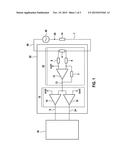
[0005] FIG. 1 shows a basic circuit diagram of such an interlock detector implemented in an interlock detector system according to the prior art. In this case, the interlock detector 50 is connected to an interlock circuit 60 and to a microprocessor 30. In the interlock circuit 60, an interlock signal 26 is generated by an interlock generator 40, which signal is passed, in the interlock circuit 60, via an interlock circuit resistor 14, a measuring resistor 4 and optionally further active and/or passive interlock participants 7. The interlock signal 26 causes a defined voltage drop across the measuring resistor 4 of the interlock circuit 60. This defined voltage drop is tapped off via a differential amplifier 20 consisting of an operational amplifier 12 having a respective resistor 3, 6, 8 both in its two input branches and in its feedback branch, is possibly adapted to the signal level to be evaluated at an input branch of the operational amplifier 12 using an offset voltage Uref1 and is amplified. The amplified signal is supplied to a comparator circuit 10 via the output 13 of the differential amplifier 20. The comparator circuit 10 consists of two operational amplifiers 16, 18 in which an input of one operational amplifier 16 is connected to an input of the other operational amplifier 18. The signal passed to this connection 13 by the differential amplifier 20 is compared, by the first operational amplifier 16 of the comparator circuit 10, with an upper limit value Uref2 which is supplied to the unconnected input of the operational amplifier 16. The signal resulting from the evaluation of the comparison is supplied directly to the microprocessor 30 via the output 9 of the operational amplifier 16 of the comparator circuit 10. The signal passed to the connection 13 by the differential amplifier 20 is compared, by the second operational amplifier 18 of the comparator circuit 10, with a lower limit value which is supplied to the unconnected input of the operational amplifier 18. The signal resulting from the evaluation of the comparison is supplied directly to the microprocessor 30 via the output 24 of the operational amplifier 18 of the comparator circuit 10. The received signals are then evaluated in the microprocessor within an interval of time and are compared with a desired value.
DISCLOSURE OF THE INVENTION
[0006] The interlock detector according to the invention comprises a first input to which an output signal from an interlock generator is applied, an output for providing a microprocessor with an output signal, a differential amplifier, the first and second inputs of which are connected to the first input of the interlock detector, and a comparator circuit, the input of which is connected to the output of the differential amplifier and the output of which is connected to the output of the interlock detector. Furthermore, the interlock detector has at least one second input to which a diagnosis signal is applied, the at least one second input being connected to the input of the comparator circuit between the comparator circuit and the differential amplifier and/or being connected to one of the first or second inputs of the differential amplifier between the first input of the interlock detector and the differential amplifier.
[0007] The advantage of the interlock detector according to the invention is the possibility of being able to check the functionality or integrity of individual components or of the entire interlock detector, even without the presence of a connection between the interlock detector and the interlock circuit or the interlock generator, by supplying diagnosis signals via the second inputs of the interlock detector. Circuit parts of the interlock detector can be individually and continuously stimulated via the diagnosis signals and their functionality or integrity can therefore be checked. The interaction between the interlock detector and the interlock generator therefore becomes superfluous for the purpose of testing and the function of the interlock detector can be checked even when the battery is disassembled, that is to say when the interlock circuit is open.
[0008] In one preferred embodiment, the interlock detector has a plurality of, preferably four, second inputs, two of which are connected to the first or second input of the differential amplifier between the first input of the interlock detector and the differential amplifier. A third second input is connected to the first input of the interlock detector or to the connecting piece between the first input of the interlock detector and the inputs of the differential amplifier via the first or second input of the differential amplifier. The remaining second input is connected to the input of the comparator circuit between the comparator circuit and the differential amplifier or to the connecting piece between the comparator circuit and the differential amplifier. Such an embodiment makes it possible to deliberately control the comparator thresholds of the comparator circuit in small steps and therefore to accurately check the function of the comparator circuit. Further diagnosis signals can be used, for example, to check the functionality of the inputs of the differential amplifier and of the interlock detector and, alternatively or additionally, a diagnosis signal can be used to concomitantly include the offset voltage, which is supplied to an input of the differential amplifier, in the test. The functionality or integrity of the first input of the interlock detector, which can be implemented by means of a measuring resistor and the two inputs of the differential amplifier in one exemplary embodiment, can be checked using the connection between the one second input and the first input of the interlock detector.
[0009] The connection between the input of the comparator circuit and the output of the differential amplifier can preferably be interrupted via an additional switching means for diagnosing the comparator circuit.
[0010] The additional switching means for interrupting the connection between the input of the comparator circuit and the output of the differential amplifier is preferably downstream of the output of the differential amplifier and upstream of the connection between the second input and the input of the comparator circuit. Opening the switching means between the input of the comparator circuit and the output of the differential amplifier makes it possible to ensure that the diagnosis signal supplied to the input of the comparator circuit cannot be influenced by the differential amplifier or by interference signals coming from the latter.
[0011] In one preferred embodiment, electrical connection paths between the second inputs of the interlock detector and the input of the comparator circuit and/or the inputs of the differential amplifier and the first input of the interlock detector are each provided with at least one switching means. Such a circuit arrangement provides a wide diagnostic range which can be reduced or increased by opening or closing the switching means in the electrical connection paths. Individual diagnosis signals can therefore be added or have other diagnosis signals superimposed on them by closing the switching means, while particular diagnosis signals can be excluded from the diagnosis by opening the switching means.
[0012] One input of the differential amplifier preferably has an additional connection for applying an offset voltage. Such an offset voltage can be used to adapt the input signal of the differential amplifier to a particular signal level to be evaluated by the comparator circuit.
[0013] The output of the interlock detector is preferably formed by the two outputs of the comparator circuit which are directly connected to the microprocessor. The advantage of such an implementation is the direct, low-loss transmission of the output signals from the comparator circuit to the microprocessor without the signals having to be "post-processed" in intermediate units. The signal obtained from a differential amplifier is therefore compared with a reference signal, for example, entirely in the comparator circuit, as a result of which the microprocessor is spared computational effort, which saves costs and space for implementing the microprocessor.
[0014] One preferred embodiment implements an interlock detector system having an interlock circuit, an interlock generator, an interlock detector, and a microprocessor, the first input of the interlock detector being connected to the interlock generator, and the output of the interlock detector being connected to the microprocessor for evaluating the output signals from the interlock detector, the microprocessor being connected to the at least one second input of the interlock detector for the purpose of providing a signal for diagnosing the interlock detector.
[0015] The advantage of such a system is that the generation of the diagnosis signals and their evaluation are combined in a digital signal-processing system, the microprocessor. This makes it possible to carry out the evaluation in a more accurate manner since fluctuations in the diagnosis signals themselves and during their generation can be concomitantly taken into account during evaluation. Furthermore, two data-processing systems need not be provided in the circuit arrangement, thus saving costs and space.
[0016] In one preferred further development of the above embodiment of the interlock detector system, the microprocessor is designed to directly generate the diagnosis signals for the interlock detector or to respectively generate the diagnosis signals via pulse width modulation signals and a respective low-pass filter between the microprocessor and the second input of the interlock detector. The advantage of such generation of the analog signal is the type of signal generation itself. The analog signal is generated with low loss using "low and high levels", as a result of which less energy needs to be used to generate the signals.
[0017] At least one switching means is preferably present between the first input of the interlock detector and the interlock generator of the interlock detector system. The interlock detector can be decoupled from the interlock generator and from the interlock circuit by opening the switching means. This is advantageous, for example while supplying a diagnosis signal, since interfering influences on the diagnosis signal by the interlock circuit or the interlock generator can be excluded by opening the switching means.
[0018] The first input of the interlock detector is preferably formed by the two inputs of the differential amplifier which tap off the input voltage of the interlock detector via a measuring resistor in the interlock circuit.
[0019] Provision is also made of a method for the self-diagnosis of an interlock detector system comprising an interlock circuit, an interlock generator, an interlock detector having a first input to which an output signal from an interlock generator is applied, an output for providing a microprocessor with an output signal, a differential amplifier, the first and second inputs of which are connected to the first input of the interlock detector, and a comparator circuit, the input of which is connected to the output of the differential amplifier and the output of which is connected to the output of the interlock detector, and a microprocessor. The method comprises the following method steps of: disconnecting the interlock detector from the interlock circuit by opening at least one switching means; generating a diagnosis signal for the interlock detector by the microprocessor; supplying a diagnosis signal, via at least one second input of the interlock detector, to the input of the comparator circuit between the comparator circuit and the differential amplifier and/or to at least one input of the differential amplifier between the differential amplifier and the first input of the interlock detector; and evaluating the output signal from the interlock detector in the microprocessor.
[0020] In one preferred further development of the above method for the self-diagnosis of an interlock detector system, the method also comprises the step of disconnecting the comparator circuit from the differential amplifier.
[0021] A battery having an interlock detector according to the invention is preferably implemented, the battery particularly preferably being in the form of a lithium ion battery. The advantage of lithium ion batteries is their comparatively high energy density.
[0022] A motor vehicle having a battery with an interlock detector according to the invention is preferably implemented, the battery being connected to a drive system of the motor vehicle.
DRAWINGS
[0023] Exemplary embodiments of the invention are explained in more detail using the drawings and the following description. In the drawings:
[0024] FIG. 1 shows a basic circuit diagram of an interlock detector implemented in an interlock detector system according to the prior art,
[0025] FIG. 2 shows a basic circuit diagram of an interlock detector according to the invention, and
[0026] FIG. 3 shows a special embodiment of the interlock detector system with an interlock detector.
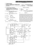
[0027] FIG. 2 shows a basic circuit diagram of an interlock detector 50 according to the invention. The interlock detector 50 has a first input 48, which can be used to tap off the output signal from an interlock generator, and an output 46, which can be used to transmit the output signal to a microprocessor. The first input 48 is connected to the first and second inputs of a differential amplifier 20. The output of the differential amplifier 20 is connected to the input of a comparator circuit 10. The output of the comparator circuit 10 is connected to the output 46 of the interlock detector 50. The illustrated interlock detector 50 according to the invention also has, purely by way of example, four further second inputs 41, 42, 43, 44 which can be used to supply diagnosis signals to the circuit. Two second inputs 41, 42 of the interlock detector 50 are connected to one of the first or second inputs of the differential amplifier 20 between the input 48 of the interlock detector 50 and the differential amplifier 20. A third second input 43 is connected to the first input 48 of the interlock detector 50 or to the connecting piece between the first input 48 of the interlock detector 50 and the inputs of the differential amplifier 20 via the first or second input of the differential amplifier 20. The remaining second input 44 is connected to the input of the comparator circuit 10 between the comparator circuit 10 and the differential amplifier 20 or to the connecting piece between the comparator circuit 10 and the differential amplifier 20. The third second input 43 is optionally directly connected to the first input 48 of the interlock detector 50.
[0028] The invention therefore relates to an interlock detector 50, to the first input 48 of which the output signal from an interlock generator is supplied. The output signal from the interlock generator is transmitted to a differential amplifier 20, the two inputs of which are connected to the first input 48 of the interlock detector 50. The output of the differential amplifier 20 is connected to the input of a comparator circuit 10 which compares the amplified input signal transmitted by the differential amplifier 20 with a reference value. The output of the comparator circuit 10 is connected to the output 46 of the interlock detector 50, to which the comparator circuit 10 transmits its output signal. Diagnosis signals can be supplied to different locations of the interlock detector 50 via four second inputs 41, 42, 43, 44 of the interlock detector 50. Two second inputs 41, 42 are preferably connected to one of the first or second inputs of the differential amplifier 20 between the first input 48 of the interlock detector 50 and the differential amplifier 20 and can be used to supply a diagnosis signal to the respective input of the differential amplifier 20. A third second input 43 is connected to the first input 48 of the interlock detector 50 or to the connecting piece between the first input 48 of the interlock detector 50 and the two inputs of the differential amplifier 20 via the first or second input of the differential amplifier 20. It can be used to diagnose precisely this first input 48. A second input 44 is preferably connected to the input of the comparator circuit 10 between the comparator circuit 10 and the differential amplifier 20 or to the connecting piece between the comparator circuit 10 and the differential amplifier 20 in order to supply a diagnosis signal to the input of the comparator circuit 10. However, only one second input, two second inputs or three second inputs can also be present in any desired combination.
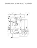
[0029] FIG. 3 shows a special embodiment of the interlock detector system having an interlock detector 50. The illustration shows a special embodiment of an interlock detector 50 according to the invention including an interlock circuit 60 with an interlock generator 40, an interlock signal 26, an interlock circuit resistor 14, two switching means 32, 33 which can be used to decouple the interlock circuit 60 from the interlock detector 50 and interlock participants 7 (not depicted), as well as a microprocessor 30. The comparator circuit 10 and the differential amplifier 20 are implemented as illustrated in FIG. 1. The output of the differential amplifier 20 is connected to the first end of a switching means 38, while the second end of the switching means 38 is connected to the input of the comparator circuit 10. The first input 48 and the output 46 of the interlock detector 50 are also implemented as illustrated in FIG. 1, with the result that the interlock detector 50 is connected to the interlock circuit 60 via the measuring resistor 4 and the comparator circuit 10 is connected to the microprocessor 30 via the two outputs 9, 24 of the two operational amplifiers 16, 18. The interlock detector 50 in FIG. 3 also has four further second inputs 41, 42, 43, 44 which are used to supply diagnosis signals to the interlock detector system. Purely by way of example, two of the second inputs 41, 42 are connected to one of the first or second inputs of the differential amplifier 20 between the first input 48 of the interlock detector 50 and the differential amplifier 20 via a respective switching means 35, 36. The third second input 43 is connected to the first input 48 of the interlock detector 50 via a switching means 37 and via the first or second input of the differential amplifier 20. The remaining second input 44 is connected to the input of the comparator circuit 10 between the comparator circuit 10 and the switching means 38 or to the connecting piece between the comparator circuit 10 and the differential amplifier 20 via a switching means 34. All second inputs 41, 42, 43, 44 of the interlock detector 50 are connected to the microprocessor 30 via a line resistor 70 and via particularly configured low-pass filters 72, 78. The low-pass filter in the connection to the two second inputs 41, 44 consists of a low-pass filter resistor 71 in the connection and a capacitor 73, the first end of which is connected to ground and the second end of which, between the line resistor 70 and the low-pass filter resistor 71, is connected to the respective connection. The low-pass filter in the connection to the other two second inputs 42, 43 consists of a parallel circuit comprising a low-pass filter resistor 77 and a capacitor 79, the first ends of which are connected to ground and the second ends of which, between the microprocessor 30 and the line resistor 70, are connected to the respective connection.
[0030] For a self-diagnosis, the switching means 32, 33 in the interlock circuit 60 can first of all be opened and the interlock detector 50 can therefore be decoupled from the interlock circuit 60. Purely by way of example, the microprocessor 30 is used to generate pulse-width-modulated diagnosis signals which are demodulated via the low-pass filters 72, 78 in the connections and are passed to at least one of the second inputs 41, 42, 43, 44 of the interlock detector 50. When the switching means 35, 36 are closed, the diagnosis signals are supplied to one of the first or second inputs of the differential amplifier 20 between the first input 48 and the differential amplifier 20. When the switching means 37 is closed, a diagnosis signal is additionally supplied to the first input 48 of the interlock detector 50 which, in this special exemplary embodiment, is formed from a measuring resistor 4 and the two inputs of the differential amplifier 20. In this case, the switching means 38 is also closed, with the result that the diagnosis signal amplified by the differential amplifier 20 can be transmitted to the input of the comparator circuit 10 via the output of the differential amplifier 20. In the comparator circuit 10, the output signal from the differential amplifier 20 is compared with an upper limit value and a lower limit value, and an output signal from the comparator circuit 10, which corresponds to the result of the comparison, is transmitted to the microprocessor 30. Alternatively or additionally, closing the switching means 34 results in a diagnosis signal being supplied to the input of the comparator circuit 10 between the comparator circuit 10 and the differential amplifier 20 or to the connecting piece between the comparator circuit 10 and the differential amplifier 20. If only the functionality of the comparator circuit is intended to be checked in this case, the connection between the comparator circuit 10 and the differential amplifier 20 is interrupted by opening the switching means 38. The output signal from the comparator circuit 10, which is caused by the diagnosis signals, is evaluated in the microprocessor 30. The second input 44 is therefore used to check the functionality of the comparator circuit 10. It can be used to deliberately individually control the comparator thresholds of the comparator circuit 10, for example. The second input 41 is used to check the function of the differential amplifier 20 and to test one of its inputs. The second input 42 can be used to check the other input of the differential amplifier 20. Alternatively or additionally, it can also be used to concomitantly include the offset voltage, which can be supplied to the respective input of the differential amplifier, in the test. The second input 43 can be used to check the integrity of the first input of the interlock detector which, in this exemplary embodiment, is implemented by means of a measuring resistor 4 and the inputs of the differential amplifier 20. Four second inputs are shown purely by way of example in FIG. 3. However, only one second input, two second inputs or three second inputs can also be present in any desired combination. At least one second input 44 is preferably provided for the purpose of diagnosing a comparator circuit 10, one second input 41 or 42 is provided for the purpose of diagnosing the differential amplifier 20 and one second input 43 is provided for the purpose of diagnosing the first input 48 of the interlock detector 50.
User Contributions:
Comment about this patent or add new information about this topic:
Images included with this patent application:
 |  |
 |  |
| New patent applications in this class: | |
| Date | Title |
|---|---|
| 2019-05-16 | On-die aging measurements for dynamic timing modeling |
| 2017-08-17 | Diagnostic circuitry for powered sensor multiple unique faults diagnostics and resistive fault tolerant interface to microprocessor |
| 2016-09-01 | Tsv testing method and apparatus |
| 2016-07-14 | Method for testing embedded systems |
| 2016-06-23 | Fault detection for a flexible probe tip |
| New patent applications from these inventors: | |
| Date | Title |
|---|---|
| 2015-11-12 | Precharging circuit for charging an intermediate circuit capacitor |
| 2014-06-19 | Dynamic line termination of communication buses in monitoring circuits for battery modules and a method for performing the line termination during the initialization of the monitoring system |
| Top Inventors for class "Electricity: measuring and testing" | |
| Rank | Inventor's name |
|---|---|
| 1 | Udo Ausserlechner |
| 2 | David Grodzki |
| 3 | Stephan Biber |
| 4 | William P. Taylor |
| 5 | Markus Vester |