Patent application title: COOLANT-SUPPLYING FLANGE FOR A COMPONENT TO BE COOLED AND COMPONENT PROVIDED WITH SUCH A FLANGE
Inventors:
Sylvain Gautier (Ennery, FR)
Frédéric Ribera (Acheres, FR)
Sylvain Favelier (Puteaux, FR)
Assignees:
VALEO SYSTEMES DE CONTROLE MOTEUR
IPC8 Class: AF28F100FI
USPC Class:
165177
Class name: Heat exchange tubular structure
Publication date: 2015-10-29
Patent application number: 20150308754
Abstract:
The invention relates to a coolant-supplying flange for a component to be
cooled, especially an exhaust gas recirculation valve, said flange
comprising a centring drum (3) in a duct (4) for the circulation of said
coolant in said component, said drum (3) extending in an axial direction,
said drum (3) being crossed by a channel (6) for the circulation of said
coolant, extending in said axial direction, said drum (3) having at least
one passage (13) allowing a transverse circulation of the fluid between
said circulation duct (4) of the component and said circulation channel
(6) of said flange.Claims:
1. A flange for supplying coolant to an exhaust gas recirculation valve
to be cooled, said flange comprising: a centering barrel for centering in
a duct for the circulation of said coolant in said component, said barrel
extending in an axial direction, said barrel having passing through it a
canal for the circulation of said coolant extending in said axial
direction, and said barrel having one or more passages allowing the fluid
a transverse circulation between said circulation duct of the component
and said circulation canal of said flange.
2. The flange as claimed in claim 1, further comprising, at the base of the barrel, a shoulder configured to collaborate with a seal intended to afford sealing between said circulation duct of the component and the outside of the component.
3. The flange as claimed in claim 2, said passage or passages being situated between said shoulder and a distal end of the barrel.
4. The flange as claimed in claim 1, said barrel being cylindrical.
5. The flange as claimed in claim 1, said barrel being of circular cross section.
6. The flange as claimed in claim 1, said passage or passages being slits extending in the direction of longitudinal extension of the barrel.
7. The flange as claimed in claim 1, said passage or passages being open axially at the distal end of the barrel.
8. The flange as claimed in claim 1, said passage or passages being three in number.
9. The flange as claimed in claim 1, said barrel further comprising an annular wall extending around the axial direction in which the passages are made, two consecutive passages between them defining a branch.
10. The flange as claimed in claim 9, said barrel being provided with reinforcing ribs, each rib extending between the center of the canal and a branch.
11. The flange as claimed in claim 10, said reinforcing ribs being oriented in the direction of longitudinal extension of said barrel.
12. A component that is to be cooled comprising: a coolant circulation duct; and a flange as claimed in claim 1 for the passage of said fluid to and/or from said duct.
13. The component as claimed in claim 12, said duct being widened in line with said barrel to create a jacket for the circulation of said coolant between said barrel and a wall of said duct.
14. The component as claimed in claim 13, said wall of the duct comprising an angular succession of ribs and grooves to limit the area of contact between the barrel and the component.
15. A valve for a combustion engine air circuit or for a combustion engine cooling circuit, comprising a component as claimed in claim 12.
Description:
[0001] The invention relates to a flange for supplying coolant to a
component that is to be cooled, and to a component equipped with such a
flange. It will find notable applications as a coolant supplying flange
of a combustion engine air circuit valve. Within the meaning of the
invention, a "combustion engine air circuit" means the circuit between
the intake inlet and the exhaust outlet of the combustion engine. The
valve may be positioned in the intake circuit, in the exhaust circuit, or
in a recirculation loop through which exhaust gases reinjected into the
intake side pass (this being more commonly known as an EGR loop).
[0002] In general, an internal combustion engine exhaust gas recirculation system makes it possible to reduce the amount of nitrogen oxides present in the exhaust gases. Conventionally, such a recirculation system comprises a bypass duct on the exhaust gas pipe, this duct being equipped with a flow regulating valve, referred to as an EGR valve, that allows the desired amount of exhaust gas to be returned to the intake side of the engine.
[0003] Such a valve therefore has passing through it gases which, although sometimes cooled before passing through the valve, are at very high temperatures. It is therefore appropriate to cool said valve and to do so it is known practice to use a coolant passing through a network of ducts that pass through the valve.
[0004] In order to circulate the liquid through the valve use is made of inlet and/or outlet flanges. These are centered on the ducts of the valve with which they communicate via a barrel that makes it easier to fit and position the flanges on the valve.
[0005] However, it has been found that the barrel insulated the valve body from the cooling circuit and locally created a hot spot near the flange. Such a lack of cooling is all the more damaging because it makes the valve more sensitive to phenomena of thermal expansion in a region which ought rather to be shielded from these phenomena in order to avoid impairing the sealing or the attachment of the flange to the body.
[0006] The invention proposes to address these problems by improving the cooling of the valve near the flange without losing the centering functionality of the flanges of the prior art.
[0007] The invention thus relates to a flange for supplying coolant to a component that is to be cooled, notably a valve, said flange comprising a centering barrel for centering in a duct for the circulation of said coolant in said component, said barrel extending in an axial direction, said barrel having passing through it a canal for the circulation of said coolant extending in said axial direction.
[0008] According to the invention, said barrel has one or more passages allowing the fluid a transverse circulation between said circulation duct of the component and said circulation canal of said flange.
[0009] That way coolant is allowed to pass in contact with at least part of the walls of the component that is to be cooled which lie facing the barrel and phenomena of local heating near the flange are limited. This then avoids stressing the material of the component in this region and this in turn enhances the reliability of the mounting of said flange both in terms of sealing and in terms of mechanical integrity.
[0010] According to various embodiments which may be considered together or separately:
[0011] said canal opens at a distal end of the barrel,
[0012] said barrel is cylindrical, notably of circular section,
[0013] said flange comprises, at the base of the barrel, a shoulder that is configured to collaborate with a seal intended to afford sealing between said circulation duct of the component and the outside of the component,
[0014] said passage or passages are situated between said shoulder and said distal end of the barrel,
[0015] said passage or passages are slits extending in the direction of longitudinal extension of the barrel,
[0016] said passage or passages are open axially at the distal end of the barrel,
[0017] said passage or passages are three in number, for example angularly distributed 120° apart,
[0018] said barrel comprises an annular wall extending around the axial direction in which the passages are formed, two consecutive passages between them defining a branch,
[0019] said barrel is provided with reinforcing ribs, each reinforcing rib being arranged in said circulation canal of the barrel from the center of the canal toward a branch,
[0020] said reinforcing ribs are oriented in the direction of longitudinal extension of said barrel.
[0021] The invention also relates to a component that is to be cooled, notably a combustion engine air circuit valve such as an exhaust gas recirculation valve or EGR valve, comprising a coolant circulation duct and a flange as described hereinabove for the passage of said fluid to and/or from said duct.
[0022] As an alternative, the invention relates to a combustion engine cooling circuit valve comprising a coolant circulation duct and a flange as described hereinabove for the passage of said fluid to and/or from said duct.
[0023] Said duct advantageously widens in line with said barrel to create a jacket for the circulation of said coolant between said barrel and a wall of said duct.
[0024] Said wall of the duct may comprise an angular succession of ribs and grooves to limit the area of contact between the barrel and the component. Said ribs and/or grooves are, for example, oriented along the longitudinal extension of the barrel. Advantageously, only the surface of the grooves is machined.
[0025] Further features and advantages of the invention will become apparent from reading the following description which relates to detailed exemplary embodiments, given with reference to the attached figures which, respectively, depict:
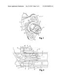
[0026] FIG. 1: a partial perspective view of one embodiment of a flange according to the invention;
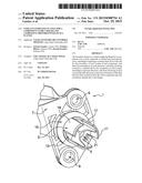
[0027] FIG. 2: a view in longitudinal section of the flange of FIG. 1 mounted in a cooling duct of an EGR valve; and
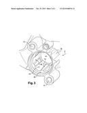
[0028] FIG. 3: a perspective view of the duct of the valve of FIG. 2, illustrated without the flange.
[0029] As illustrated in FIG. 1, the invention relates to a coolant supply flange 1 for a component that is to be cooled, notably a motor vehicle component. This may in particular be an exhaust gas recirculation valve. Such a valve is partially illustrated in FIG. 2.
[0030] Said component that is to be cooled is made for example from a cast structure or body 2, notably made of aluminum and/or aluminum alloy.
[0031] In the case of an exhaust gas recirculation valve, said body 2 comprises a gas circulation duct, not visible. A valve shut-off member, such as a valve shutter or flap, is configured to shut off said gas circulation duct to a greater or lesser extent so as to allow the rate of flow of such gases through the valve to be regulated. Said valve may comprise dynamic members, such as a gear set with cogged wheels, for actuating said shut-off member or members from a valve drive motor. It may further comprise instrumentation, notably a position sensor, for monitoring said dynamic and/or shut-off members.
[0032] In order to allow it to be cooled, said component comprises a network for the passage of a coolant, notably water to which an antifreeze, particularly glycol, has been added, this coolant coming from a vehicle cooling circuit. Said component comprises at least one circulation duct 4 for said coolant, through which duct said coolant enters and/or leaves said component.
[0033] Said flange 1 comprises a centering barrel 3 for centering it in said coolant circulation duct 4 in said component. Said barrel 3 extends in an axial direction D. It defines a circulation canal 5 for said coolant which extends in said axial direction D.
[0034] As is more visible in FIG. 1, said barrel 3 is, for example, cylindrical, notably of circular cross section. Said circulation canal 5 may likewise be of circular section so that said barrel 3 is formed of an annular wall 17. Said canal 5 opens in said axial direction D, for example at a distal end 11 of the barrel 3. Said barrel 3 encourages insertion of the flange 1 into the component that is to be cooled and correct positioning with respect to said component.
[0035] In this regard, said flange 1 here comprises a mounting plate 7 for fixing it to said component. Said mounting plate 7 is, for example, perpendicular to said barrel 3. It may comprise orifices 9 for the passage of fixing screws, not illustrated. For its part, said component that is to be cooled comprises, for example, bores 6 for fixing said flange 1 to said component that is to be cooled using said screws.
[0036] Moreover, said component that is to be cooled may comprise a seal 8 to seal between said coolant circulation duct 4 and the outside of the component that is to be cooled. Said seal 8 is situated between said flange 1 and said component that is to be cooled and it will be appreciated that sealing is notably dependent on correct positioning of said flange 1 with respect to said component.
[0037] Said flange 1 may comprise, at the base of the barrel 3, a shoulder 15 configured to collaborate with the seal 8. Said flange 1 may furthermore of course comprise one or more connecting orifices, not illustrated, connecting to the cooling circuit supplying said component that is to be cooled.
[0038] That being so, according to the invention, said barrel 3 has one or more passages 13 allowing transverse circulation of the fluid between said circulation duct 4 of the component and said circulation canal 5 of said flange 1. Transverse here means a direction that is inclined with respect to the longitudinal direction of the barrel 3.
[0039] Said coolant is thus directed not only toward the distal end 11 of the barrel 3 but also toward a wall 10 of the circulation duct 4 that lies laterally facing said barrel 3. Said wall 10 may consequently likewise be cooled. That then avoids the creation of hot spots that experience strong thermal expansion phenomena, stressing the material of the body 2 near the flange 1 and risking impediment of the sealing afforded by said seal 8 and impediment of the good mechanical connection between the flange 1 and the component in the region of said bores 6.
[0040] Said passage or passages 13 are situated, for example, between said shoulder 15 and said distal end 11 of the barrel 3. Said passage or passages 13 here are slits extending in the direction of longitudinal extension of the barrel, said slits 13 being open axially to the distal end 11 of the barrel 3. Said slit or slits 13 are three in number here, evenly spaced apart. Said slits 13 are separated by branches 19 of said barrel 3 that extend angularly between two adjacent slits 13 of said barrel. In other words, said slits 13 are formed by interruptions in the annular wall 17 of said barrel 3. Said annular wall 17 here is defined by said branches 19 which are intended to project from the shoulder 15. The distal end 11 of the barrel 3 is defined by a distal end of said branches 19.
[0041] Said barrel 3 is advantageously provided with reinforcing ribs 21, arranged in said circulation canal 5 of the barrel 3 between the branches 19. Said reinforcing ribs 21 are oriented, for example, in the direction of longitudinal extension D of said barrel 3, particularly radially. They are three in number here and arranged in a star shape from the longitudinal direction of said canal 5. In that way they divide said canal 5 into three sub-canals for the passage of the coolant.
[0042] As is more visible in FIG. 2, said duct 4 for example widens in line with said barrel 3 to create a jacket 12 for the circulation of said coolant between said barrel 3 and the wall 10 of said duct 4.
[0043] With reference to FIG. 3 it may be noted that said wall 10 of the duct 4 comprises, particularly in the region of said jacket 12, an angular succession of ribs 14 and grooves 16 to limit the area of contact between the barrel 3 and the component that is to be cooled. Said ribs 14 and/or grooves 16 at one of their longitudinal ends have a shoulder 20 that faces the shoulder 15 of the flange 1, said seal 8 being placed between said shoulders 15, 20.
[0044] Advantageously, only the faces of said ribs 14 are machined, while the surface finish of said grooves 16 is as-cast.
[0045] Said ribs 14 and/or grooves 16 are oriented, for example, in the longitudinal direction of the barrel 3. They may have a substantially trapezoidal shape, the long base of the ribs 14 being situated at one and the same axial end of said jacket 12 as the short base of the grooves 16, and vice versa at the opposite end.
[0046] It may also be noted from FIG. 3 that said component may comprise a part 18 projecting from the rest of its body 2 in the region of which projecting part a mouth of said circulation duct 4 and/or said bores 6 are formed.
User Contributions:
Comment about this patent or add new information about this topic:
Images included with this patent application:
 |  |
 |
| New patent applications in this class: | |
| Date | Title |
|---|---|
| 2019-05-16 | Heat exchanger tube |
| 2019-05-16 | Heat exchanger tube |
| 2016-06-09 | Metal-based microchannel heat exchangers made by molding replication and assembly |
| 2016-04-28 | Heat exchanger with non-linear coil |
| 2016-04-21 | Aluminium composite material having an internal solder layer |
| New patent applications from these inventors: | |
| Date | Title |
|---|---|
| 2015-12-03 | Valve, particularly an exhaust gas recirculation valve |
| 2015-08-27 | Fluid flow valve, especially for recirculated exhaust gas |
| Top Inventors for class "Heat exchange" | |
| Rank | Inventor's name |
|---|---|
| 1 | Levi A. Campbell |
| 2 | Chun-Chi Chen |
| 3 | Tai-Her Yang |
| 4 | Robert E. Simons |
| 5 | Richard C. Chu |