Patent application title: Deburring Brush
Inventors:
Bowen Xue (Qinhuangdao, CN)
Jiandong Guo (Qinhuangdao, CN)
Yongning Wang (Qinhuangdao, CN)
Yongning Wang (Qinhuangdao, CN)
Zhihua Zhu (Qinhuangdao, CN)
Zhihua Zhu (Qinhuangdao, CN)
Changhai Li (Qinhuangdao, CN)
Changhai Li (Qinhuangdao, CN)
Assignees:
KSM CASTINGS QINHUANGDAO CO., LTD.
IPC8 Class: AB24D1310FI
USPC Class:
451468
Class name: Centrifugal force urged tools flexible flail tools including self-sustaining tools
Publication date: 2015-10-29
Patent application number: 20150306740
Abstract:
The present invention discloses a deburring brush, comprising a pressing
plate, jacking posts, copper sleeves, gaskets, guide posts, springs and
bristle units. When the bristle units need replacement, it only needs to
place the deburring brush on the ground and then press down edges of the
front side of a top plate, so that all the bristle units will fall off
against the suction force of strong magnets under the action of each
jacking post. According to the present invention, it avoids being time
consuming and labor intensive due to removing the bristle units one by
one by using a screw driver or other similar devices while replacing the
bristle units, and at the same time the replacing speed of bristles is
greatly increased.Claims:
1. A deburring brush, comprising a pressing plate (1), jacking posts (2),
copper sleeves (3), gaskets (4), guide posts (5), springs (6), a bottom
plate (7), magnets (8), a top plate (9) and bristle units (10),
characterized in that the magnets (8) are fixed between the bottom plate
(7) and the top plate (9), and the magnets (8) grip the bristle units
(10), thus forming a body of the deburring brush; the guide posts (5) are
fixed below the bottom plate (7), and the copper sleeves (3) cooperating
with the guide posts (5) are embedded on the pressing plate (1); the
pressing plate (1), above which are mounted the jacking posts (2), is
fixed between the springs (6) and the gaskets (4) at the ends of the
guide posts (5); and the top ends of the jacking posts (2) pass through
holes of the bottom plate (7) and the magnets (8), and are in contact
with the bottoms of the bristle units (10).Description:
TECHNICAL FIELD
[0001] The present invention relates to a surface treatment device, more particularly to a metal surface treatment device.
BACKGROUND ART
[0002] During manufacturing process of aluminum alloy wheels, deburring cost accounts for a very large part of the overall cost due to huge consumption of deburring brushes. More and more enterprises have begun exploring and developing a variety of novel deburring brushes to reduce the deburring cost. A deburring brush with replaceable bristles is a future development trend of wheel deburring brushes due to its flexibility, its chassis part being reusable, thus greatly reducing the cost. However, how to make it convenient to disassemble the shortened bristles while reducing the cost is a new technical problem we are faced with.
[0003] Invention Contents:
[0004] An object of the present invention is providing a wheel deburring brush with conveniently replaceable bristles.
[0005] To achieve the above object, the present invention adopts the following technical solution: a deburring brush comprises a pressing plate, jacking posts, copper sleeves, gaskets, guide posts, springs, a bottom plate, magnets, a top plate and bristle units. The magnet is fixed between the bottom plate and the top plate, and the magnets grip the bristle units, thus forming a body of the deburring brush.
[0006] The guide posts are fixed below the bottom plate, and the copper sleeves cooperating with the guide posts are embedded on the pressing plate; the pressing plate, above which are mounted the jacking posts, is fixed between the springs and the gaskets at the ends of the guide posts; and the top ends of the jacking posts pass through holes of the bottom plate and the magnets, and are in contact with the bottoms of the bristle units.
[0007] When the bristle units need replacement, it only needs to place the deburring brush on the ground and then press down edges of the front side of the top plate, so that all the bristle units will fall off against the suction force of the strong magnets under the action of each jacking post.
[0008] According to the present invention, it avoids being time consuming and labor intensive due to removing the bristle units one by one by using a screw driver or other similar devices while replacing the bristle units, and at the same time the replacing speed of bristles is greatly increased.
DESCRIPTION OF DRAWINGS
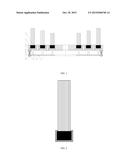
[0009] FIG. 1 is a front view of an improved displaceable wheel deburring brush according to the present invention.
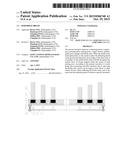
[0010] FIG. 2 is a front view of a bristle unit of an improved displaceable wheel deburring brush according to the present invention.
[0011] In the figures, 1--pressing plate, 2--jacking post, 3--copper sleeve, 4--gasket, 5--guide post, 6--spring, 7--bottom plate, 8--magnet, 9--top plate, 10--bristle unit.
DETAILED DESCRIPTION
[0012] Details and operation of the specific device provided by the present invention will be described below in conjunction with the accompanying drawings.
[0013] The deburring brush comprises a pressing plate 1, jacking posts 2, copper sleeves 3, gaskets 4, guide posts 5, springs 6, a bottom plate 7, magnets 8, a top plate 9 and bristle units 10. The magnets 8 are fixed between the bottom plate 7 and the top plate 9, and the magnets 8 grip the bristle units 10, thus forming a body of the deburring brush.
[0014] The guide posts 5 are fixed below the bottom plate 7, and the copper sleeves 3 cooperating with the guide posts 5 are embedded on the pressing plate 1; the pressing plate 1, above which are mounted the jacking posts 2, is fixed between the springs 6 and the gaskets 4 at the ends of the guide posts 5; and the top ends of the jacking posts 2 pass through holes of the bottom plate 7 and the magnets 8, and are in contact with the bottoms of the bristle units 10.
[0015] During operation, when the bristle units 10 need replacement, it only needs to place the deburring brush on the ground and then press down edges of the front side of the top plate 9, so that all the bristle units 10 will fall off against the suction force of the magnets 8 under the action of each jacking post 2.
User Contributions:
Comment about this patent or add new information about this topic:
Images included with this patent application:
 |  |
| Similar patent applications: | |
| Date | Title |
|---|---|
| 2015-11-26 | Abrasive-delivery apparatuses for use with abrasive materials in abrasive-jet systems and related apparatuses, systems, and methods |
| New patent applications in this class: | |
| Date | Title |
|---|---|
| 2014-09-18 | Sand flap work piece finishing tool |
| New patent applications from these inventors: | |
| Date | Title |
|---|---|
| 2022-03-31 | Method for extending service life of a sacrificial-layer-free aluminum alloy wheel by laser shock |
| 2020-12-31 | Wheel positioning surface correction device |
| 2020-09-17 | Automobile hub with hollow rim, hub assembling method and automobile |
| 2019-10-17 | Device for removing valve hole sealing substitute from hub |
| Top Inventors for class "Abrading" | |
| Rank | Inventor's name |
|---|---|
| 1 | Boguslaw A. Swedek |
| 2 | Hung Chih Chen |
| 3 | Jeffrey Drue David |
| 4 | Dominic J. Benvegnu |
| 5 | Chien-Min Sung |