Patent application title: Hand-Held Power Tool with an Electromotive Drive and at least a First Housing Part
Inventors:
Manfred Lutz (Filderstadt, DE)
Manfred Lutz (Filderstadt, DE)
Florian Esenwein (Leinfelden-Echterdingen, DE)
Joerg Maute (Sindelfingen, DE)
Joachim Schadow (Stuttgart, DE)
Joachim Schadow (Stuttgart, DE)
Daniel Barth (Leinfelden-Echterdingen, DE)
Daniel Barth (Leinfelden-Echterdingen, DE)
Cornelius Boeck (Kirchheim, DE)
Helmut Wanek (Kirchheim/neckar, DE)
Helmut Wanek (Kirchheim/neckar, DE)
Manfred Schuele (Sulzbach-Laufen, DE)
Manfred Schuele (Sulzbach-Laufen, DE)
IPC8 Class: AB24B2302FI
USPC Class:
451359
Class name: Frame or mount portable abrader rotary disk tool
Publication date: 2014-12-18
Patent application number: 20140370791
Abstract:
A hand-held power tool comprises an electromotive drive that is
configured to drive an output shaft and that is positioned in a first
housing part, wherein the electromotive drive and the output shaft define
a common first axis. The hand-held power tool further comprises an
electronic system that is configured to energize the electromotive drive
and that is positioned in a second housing part. The second housing part
is elongated and includes a grip that is distal from the electromotive
drive. The second housing part defines a second axis that is at an angle
to the first axis between 60° and 120°.Claims:
1. A hand-held power tool, comprising: a first housing part; a second
housing part; an electromotive drive configured to drive an output shaft
and positioned in the first housing part, the electromotive drive and the
output shaft defining a common first axis; and an electronic system
configured to energize the electromotive drive and positioned in the
second housing part, wherein the second housing part is elongated and
includes a grip that is distal in relation to the electromotive drive,
and defines a second axis that is positioned at an angle in relation to
the first axis; and wherein the angle is between 60.degree. and
120.degree..
2. The hand-held power tool according to claim 1, wherein the angle is between 80.degree. and 110.degree..
3. The hand-held power tool according to claim 1, wherein the first housing part has a height along the first axis between 60 mm and 150 mm.
4. The hand-held power tool claim 1, wherein the second housing part is formed by one or a plurality of housing shells, and is fastened to the first housing part.
5. The hand-held power tool according to claim 1, wherein the second housing part is rotatably mounted to the first housing part.
6. The hand-held power tool according to claim 1, wherein: the electromotive drive is a modular electromotive drive; the first housing part includes an inner flange; and the modular electromotive drive is fastened to the inner flange.
7. The hand-held power tool according to claim 1, further comprising an outer flange that outwardly closes off the first housing part.
8. The hand-held power tool according to claim 7, further comprising: a protective cover, wherein the outer flange includes a collar; and wherein the protective cover is attached to the collar.
9. The hand-held power tool according to claim 1, wherein the electromotive drive is an electronically commutated electric motor.
10. The hand-held power tool according to claim 1, wherein the electromotive drive is a multi-pole electromotive drive having six or more pairs of poles.
11. The hand-held power tool according to claim 9, further comprising a tool spindle, wherein the electronically commutated electric motor is configured to drive the tool spindle.
12. The hand-held power tool according to claim 1, wherein the second housing part includes a fan configured to cool the electronic system.
13. The hand-held power tool according to claim 1, wherein the first housing part includes at least one sensor configured to detect a rotational position of the electromotive drive.
14. The hand-held power tool according to claim 1, wherein the hand-held power tool is an angle grinder.
Description:
[0001] This application claims priority under 35 U.S.C. § 119 to
patent application no. DE 10 2013 210 962.8, filed on Jun. 12, 2013 in
Germany, the disclosure of which is incorporated herein by reference in
its entirety.
[0002] The disclosure relates to a hand-held power tool with an electromotive drive and at least a first housing part.
BACKGROUND
[0003] A hand-held power tool with an electronically commutated electric motor, a motor directly driving a tool spindle, is known from DE 10 2006 054 267. This hand-held power tool is difficult to handle from an ergonomic point of view, particularly when there are relatively high forces. Moreover, there is insufficient space available for the components required for a higher motor output.
SUMMARY
[0004] A hand-held power tool according to the disclosure, by contrast, the advantage of good usability on the one hand and additional space on the other. It is proposed that the hand-held power tool should be equipped with an electromotive drive acting on an output shaft. The output shaft and the electromotive drive are arranged in a first housing part of the hand-held power tool. The electromotive drive and the output shaft define a common first axis. An electronic system for energizing the electromotive drive is accommodated by a second housing part of the hand-held power tool. The second housing part is advantageously configured as an elongated housing which defines a second axis. The second axis penetrates the electronic system and advantageously extends along the second housing part in an axial direction of the second housing part during this. In so doing, it crosses the first axis at a point which lies on a motor shaft.
[0005] "Elongated" should be understood to mean that a particularly axial extension of the second housing part is greater than a length, in particular a height h of the first housing part. The second housing part is advantageously configured as a handle. The term "handle" should be understood to mean a component about which at least one of a user's hands can be placed, in order to guide a hand-held power tool. In order to achieve great flexibility in the intended use of the hand-held power tool, the angle a enclosed by the first axis and the second axis is advantageously between 60° and 120°.
[0006] By means of the features indicated in the disclosure, advantageous developments of the hand-held power tool are possible. In this way, the handling properties are improved, particularly when greater forces act in the region of the output shaft, when the angle a is between 80° and 110°, but preferably 90°. The angle specification contains deviations which are not possible and which may be caused by production tolerances.
[0007] A height h is defined as an extension of the first housing part of the hand-held power tool in the direction of the first axis. The height h advantageously lies between 60 mm and 150 mm, particularly between 70 mm and 130 mm, but preferably between 80 mm and 110 mm.
[0008] Installation space in the hand-held power tool suitable for accommodating electric motors is thereby created, said motors being suitable for releasing high torques and therefore being able to work as a direct drive without the need for a gear.
[0009] If the second housing part is constructed from one or a plurality of housing shells, good producibility is guaranteed. The second housing part advantageously encloses the first housing part at least in part, by overlapping said part at least partially in a radial and/or axial direction.
[0010] The second housing part is advantageously fastened, for example screwed, to the first housing part, so that a hand-held power tool optimized in terms of its handling properties and ergonomics is thereby created.
[0011] The second housing part may advantageously be rotatably mounted in respect of the first housing part. The hand-held power tool can therefore be used for more than one application. If the hand-held power tool is configured as an angle grinder, for example, it may be used through the rotatable mounting of the two housing parts in respect of one another both for grinding and also for cutting.
[0012] It is advantageous for the electromotive drive to be modular in design. In this way, the drive can preferably be easily varied in its performance design with otherwise similar conditions.
[0013] An outer flange advantageously closes off the first housing outwardly and can easily be removed if necessary.
[0014] The outer flange advantageously exhibits a collar. In this way, additional components of the hand-held power tool such as a protective cover, for example, can be mounted on the outer flange very easily.
[0015] The electromotive drive is advantageously realized by an electronically commutated electric motor. In this way, a high service life can be achieved for the electromotive drive. If the electronically commutated electric motor is an external rotor motor, the electromotive drive is robustly designed and is able to deliver high torques from a standing position. A drive of this kind is therefore particularly suitable for applications in which high torques are required.
[0016] A high torque is achieved by means of a multi-pole electromotive drive design with at least six or more pairs of poles.
[0017] The electromotive drive advantageously works as a direct drive. A "direct drive" should be understood to mean that the electronically commutated motor is connected to a tool spindle without a gear being inserted in between.
[0018] If the second housing accommodates a fan, the electronic system can be effectively cooled. The risk of overheating is thereby reduced.
[0019] If a sensor for detecting the rotational position of the electromotive drive is accommodated by the first housing, the sensor is protected from mechanical vibrations and loads, as they are coupled via the output shaft, for example.
[0020] A series of advantages emerges if the hand-held power tool is configured as an angle grinder without an angular gear. Hence, for example, high electromotive drive performance coupled with low wear and good hand-held power tool handling properties are guaranteed.
[0021] Exemplary embodiments of a hand-held power tool according to the disclosure are illustrated in the drawings and explained in greater detail in the following description.
BRIEF DESCRIPTION OF THE DRAWINGS
[0022] In the drawings:
[0023] FIG. 1 shows a first hand-held power tool according to the disclosure as a schematic representation,
[0024] FIG. 2 shows a partial view of an electronically commutated electric motor for a hand-held power tool according to the disclosure as a schematic representation,
[0025] FIG. 3 shows a second exemplary embodiment of the hand-held power tool according to the disclosure as a schematic overview representation,
[0026] FIG. 4 shows a second partial view of the electronically commutated electric motor for the hand-held power tool according to the disclosure as a schematic representation.
DETAILED DESCRIPTION
[0027] The same reference numbers are used for the same components occurring in the different exemplary embodiments.
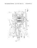
[0028] FIG. 1 shows a first embodiment of a hand-held power tool 10 according to the disclosure with an electromotive drive 14 acting on an output drive 12. The electromotive drive 14 is accommodated in the exemplary embodiment in FIG. 1 by a first housing part 16 of the hand-held power tool 10. An electronic system 18 for energizing the electromotive drive 14 is received by a second housing part 20 of the hand-held power tool 10. The electromotive drive 14 and the output drive 12 form a common first axis 22. The first axis 22 penetrates the output shaft 12. The second housing part 20 is configured as an elongated housing which forms a grip 24 that is distal from the electromotive drive 14. The second housing part 20 defines a second axis 26 which is at an angle a to the first axis 22. The second axis 26 penetrates the electronic system 18 and in so doing advantageously extends along the second housing part 20 in an axial direction of the second housing part 20. As can be seen from FIG. 1, the angle a lies between 60° and 120°, but particularly between 80° and 110°. The realization of the angle a is theoretically depicted in FIG. 1. The origin of the angle a lies at the point of intersection between the two axes 22, 26. In practical terms, the realization of a would take place via a hinge which is located on the second axis 26, particularly in the region between the electronic system 18 and the electromotive drive 14. The origin of the angle a then lies at the center of the hinge.
[0029] The electromotive drive 14 comprises an electronically commutated electric motor 28 which drives the output shaft 12. The output shaft 12 continues with a tool spindle 32. The tool spindle 32 supports a machining tool 34. In the exemplary embodiment 1 the hand-held power tool 10 is configured as an angle grinder. The machining tool 34 of an angle grinder is a grinding, cutting or roughing disk, for example.
[0030] A geometric extension of the first housing part 16 is defined by a height h. The height h extends along the first axis 22 between 60 mm and 150 mm, particularly between 70 mm and 130 mm, but preferably between 80 mm and 110 mm. Within the height h lies a length l of a rotor 36 belonging to the electromotive drive 14. The electromotive drive 14 is configured as a so-called external rotor motor in which the length l of the rotor 36, among other things, but also the diameter d of the rotor 36 determine the torque that can be transmitted to the output shaft 12 by the electromotive drive 14.
[0031] The second housing part 20 is constructed from at least one housing shell 38. The housing shell 38 is joined to a further housing shell not shown in the FIG. 1, for the purposes of providing an overview, to form the handle 24. The dividing plane between both housing shells lies in the image plane of an observer in this case. The second housing part 20 partially encloses the first housing part 16, in which a first wall 40 belonging to the second housing part 20 is pushed via a second wall 42 belonging to the first housing part 16 and fastened thereto. The first wall 40 runs flush to the second wall 42. The connection of both housing parts 16, 20 usually takes place by screwing. It is also conceivable, however, that both housing parts 16, 20 are connected by other joining methods such as riveting, welding or adhesion.
[0032] The second housing part 20 is mounted rotatably with respect to the first housing part 16. A 0° position between the two housing parts 16, 20 is depicted in FIG. 1. A 90° position is achieved by turning the first housing part 16 or the second housing part 20 through 90° in or against the line of vision of an observer by loosening or tightening a fixing device not shown in greater detail.
[0033] The electromotive motor 14 is, as can be seen from FIG. 1, modular in design. It contains a stator 50 with windings 52 and the rotor 36 with permanent magnets 48. As shown in FIGS. 1 and 3, stop elements are configured as so-called screw bosses 58 on a first wall 56 in the first housing part 16. The first wall 56 is part of the first housing part 16 on the side facing away from the machining tool 34. An inner flange 62 is accommodated by the first housing part 16, in which it is arranged on the screw bosses 58 and fastened. The inner flange 62 exhibits through-holes 64 for fastening, through which fastening means are inserted. The fastening means are usually screws, so that the inner flange 62 is screwed onto the first housing part 16.
[0034] An outer flange 66 closes the first housing part 16 outwardly at the output end. The output end in this case should be understood to mean the end of the output shaft 12 on which the machining tool 34 is mounted.
[0035] The outer flange 66 has a collar 68, to which a protective cover 70 can be attached.
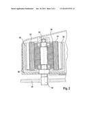
[0036] The electromotive drive 14 is realized by an electronically commutated electric motor 28. FIG. 2 shows a section through an external rotor motor. In motors of this kind, the magnetic field is generated by permanent magnets 48 which are arranged in the rotor 36. A stator packet 50 supports the windings 52. When commutating is necessary, the angle position of the permanent magnet 48 is detected in the rotor 36 via one or a plurality of sensors 54 and evaluated by the electronic system 18. Using the angle setting of the rotor 36 and the desired direction of rotation, the corresponding windings 52 are energized by the electronic system 18, in order to generate the required torque. It is also conceivable, however, that the commutating takes place in a sensorless manner through the detection of a counter-voltage triggered in the stator windings.
[0037] The electronically commutated electric motor 28 drives the spindles 32 directly. "Directly" should be understood to mean that the electronically commutated electric motor 28 is connected to the tool spindle 32 without the insertion of a gear.
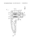
[0038] In a further exemplary embodiment of the hand-held power tool 10 according to the disclosure which is shown in FIG. 3, the spindle 32 forms a separate component to the motor shaft 30. The spindle 32 is connected to the motor shaft via a coupling part 31. In order to transfer the torque from the motor shaft 30 to the tool spindle 32, the coupling part 31 has internal toothing 33 on the inside which engages with the external toothing 37 on the motor shaft.
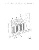
[0039] The electronically commutated electric motor 28 is, as shown in detail in FIG. 4, of multi-pole design and may exhibit six or more pairs of poles. The number of pairs of poles is the number of magnetic poles 74. A pair of poles is formed from two poles 74. The number of pairs of poles determines, as does the frequency, the speed and torque of the electric motor 28. The torque to be achieved increases to a disproportionately small degree up to a certain limit with the number of pole pairs. This should be particularly observed in relation to the design of electric motors 28.
[0040] In the second housing part 20, as shown in FIG. 1, a fan 72 for cooling the electronic system 18 is accommodated between the electronic system 18 and the first housing part 16. The fan 72 may have its own drive which drives the fan 72. Since the electronic system 18 is more powerful in the case of hand-held power tools 10 with electronically commutated electric motors 28 and is of larger design, both in terms of size and volume, than in the case of brush motors, the cooling of the electronic system 18 plays an increasingly important part.
[0041] As shown in FIG. 4, the first housing part has a sensor 54 for detecting the rotational position of the rotor 36. The sensor 54 measures the angle position of the rotor 36. The electronic system 18 evaluates the signals and energizes the stator windings 52 according to the result.
[0042] The hand-held power tool 10 is configured as an angle grinder without an angular gear in the exemplary embodiment. It is also conceivable for other applications, such as orbital sanders or similar, to be used.
User Contributions:
Comment about this patent or add new information about this topic:
| People who visited this patent also read: | |
| Patent application number | Title |
|---|---|
| 20210353884 | METHODS, SYSTEMS AND DEVICES FOR NON-INVASIVE VENTILATION INCLUDING A NON-SEALING VENTILATION INTERFACE WITH AN ENTRAINMENT PORT AND/OR PRESSURE FEATURE |
| 20210353883 | TIP & ASSEMBLY FOR THERMAL EXTRACTION DEVICE |
| 20210353882 | Coating a Respiratory System |
| 20210353881 | DRY POWDER INHALER |
| 20210353880 | MEDICINE INFUSION APPARATUS INCLUDING THERMOELECTRIC MODULE |
Images included with this patent application:
 |  |
 |  |
 |
| Similar patent applications: | |
| Date | Title |
|---|---|
| 2015-03-26 | Cmp conditioner pads with superabrasive grit enhancement |
| 2015-03-05 | Grinders with friction drives |
| 2014-08-28 | Handheld power tool |
| 2015-03-26 | Wall trim finishing apparatus |
| 2015-02-05 | Hand-guided power tool |
| New patent applications in this class: | |
| Date | Title |
|---|---|
| 2019-05-16 | Long-life abrasive pad assembly |
| 2016-07-07 | Grinder |
| 2016-06-30 | Tool holder and handheld abrading machine |
| 2016-02-25 | Pad for supporting abrasive disc |
| 2016-02-04 | Heavy-duty hand-held power tool |
| New patent applications from these inventors: | |
| Date | Title |
|---|---|
| 2022-09-22 | Machine tool device |
| 2022-08-04 | Hand-held power tool |
| 2022-03-10 | Removable dust collection apparatus, in particular removable dust collection container, for a hand-held power tool |
| 2022-01-06 | Safety braking device with two braking stages |
| 2021-07-01 | Sealing device for sealing at least one storage and/or packaging device for durable goods, particularly machine tools, and/or for sealing at least one piece of information |
| Top Inventors for class "Abrading" | |
| Rank | Inventor's name |
|---|---|
| 1 | Boguslaw A. Swedek |
| 2 | Hung Chih Chen |
| 3 | Jeffrey Drue David |
| 4 | Dominic J. Benvegnu |
| 5 | Chien-Min Sung |