Patent application title: PROCESS FOR MILD HYDROCRACKING OF HEAVY HYDROCARBON FRACTIONS WITH OPTIMIZED THERMAL INTEGRATION
Inventors:
Romina Digne (Lyon, FR)
Heloise Dreux (Lyon, FR)
Frederic Feugnet (Lyon, FR)
Frederic Feugnet (Lyon, FR)
Nicolas Lambert (Issy-Les-Moulineaux, FR)
Assignees:
IFP Energies nouvelles
IPC8 Class: AC10G6702FI
USPC Class:
208 97
Class name: Chemical conversion of hydrocarbons with subsequent treatment of products refining
Publication date: 2014-12-04
Patent application number: 20140353211
Abstract:
This invention describes a process for mild hydrocracking of heavy
hydrocarbon fractions of the vacuum distillate type or the deasphalted
oil type with optimized thermal integration for the purpose of reducing
the cost of the exchangers that are used as well as greenhouse gas
emissions.Claims:
1) Process for mild hydrocracking of a fraction of the vacuum distillate
(DSV or VGO) type or deasphalted oil (DAO) type for the purpose of
constituting the feedstock of a catalytic cracking unit, comprising: A
mild hydrocracking zone R, A high-pressure hot separator tank B-1, whose
feedstock constitutes the effluent obtained from R, A high-pressure cold
separator tank B-2, whose feedstock constitutes the gas stream obtained
from B-1, A low-pressure cold separator tank B-3, whose feedstock is the
liquid stream obtained from B-2, A zone K for washing with an amine and
for compression of the gaseous effluent obtained from B-2, called
recycled hydrogen, A pump P-2 compressing the VGO feedstock before mixing
with the recycled hydrogen obtained from K and the addition of hydrogen,
A stripper C-1 of the liquid streams obtained from B-1 and B-3, whose
bottom product constitutes the feedstock of the fractionator C-2, A
fractionator C-2, separating the naphtha, the diesel and the residue, and
comprising a diesel-circulating reflux, A diesel stripper C-3, stripping
the diesel obtained from C-2, A furnace F-1 heating the feedstock of the
mild hydrocracking zone R, A furnace F-2 heating the feedstock of the
fractionator C-2, with said process comprising optimized heat exchanges
between different streams at different levels of said process, with said
exchanges being the following: a) At the exchange train of the heating of
the low-pressure feedstock, by exchange: In E-7 A and E-7 B with the
stripped diesel obtained from C-3, In E-4 with the gaseous effluent
obtained from B-1, In E-10 A and E-10 B/C with the bottom of the
fractionator, And in the following order: E-7 B, E-4, E-10 A, E-7 A, E-10
B/C, b) At the exchange train of the cooling of the gaseous effluent
obtained from B-1, by exchange: In E-3 with the mixture of the hydrogen
addition and a portion of the recycled hydrogen, And then in E-4 with the
low-pressure feedstock, c) At the exchange train of the heating of the
liquid obtained from B-3, by exchange: In E-6 with the diesel-circulating
reflux, And then in E-5 with the bottom of the fractionator C-2, d) At
the exchange train of the cooling of the effluent from the mild
hydrocracking zone R, by exchange: In E-1 with the high-pressure
feedstock of R, with E-1 consisting of several calendars, In E-2 with the
feedstock of the fractionator C-2, with E-2 being able to consist of
several calendars and the calendars being able to be located between
calendars of E-1, e) At the exchange train of the cooling of the bottom
of the fractionator C-2, by exchange: First in E-8 with the diesel for
reboiling the diesel stripper C-3, Then in E-9 with the feedstock of the
fractionator C-2, Then in E-5 with the liquid obtained from B-3, And
finally in E-10 with the feedstock of the process, with E-10 being able
to consist of several calendars in series.Description:
FIELD OF THE INVENTION
[0001] The invention relates to the field of the soft hydrocracking of hydrocarbons ("mild hydrocracking," in English). The invention consists in optimizing the thermal integrations between the hot and cold streams of the unit so as to reduce the consumption of hot and cold utilities, and, as a result, the greenhouse gas (GHG) emissions.
[0002] This invention can be viewed as an enhancement of the application filed on Dec. 18, 2012 under No. FR 12/03,469.
EXAMINATION OF THE PRIOR ART
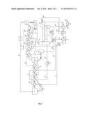
[0003] The prior art is shown by the diagram of FIG. 1 that will be described in detail in the paragraph "detailed description of the invention."
SUMMARY DESCRIPTION OF THE FIGURES
[0004] FIG. 1 shows the thermal integrations of a mild hydrocracking process according to the prior art.
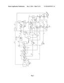
[0005] FIG. 2 shows the new thermal integrations of the mild hydrocracking process according to the invention.
SUMMARY DESCRIPTION OF THE INVENTION
[0006] This invention describes a process for mild hydrocracking of a fraction of the vacuum distillate (DSV or "VGO" in English) type or the deasphalted oil (DAO) type for the purpose of constituting the feedstock of a catalytic cracking unit, comprising:
[0007] A mild hydrocracking zone R,
[0008] A high-pressure hot separator tank B-1, whose feedstock constitutes the effluent obtained from R,
[0009] A high-pressure cold separator tank B-2, whose feedstock constitutes the gas stream obtained from B-1,
[0010] A low-pressure cold separator tank B-3, whose feedstock is the liquid stream obtained from B-2,
[0011] A zone K for washing with an amine and for compression of the gaseous effluent obtained from B-2, called recycled hydrogen,
[0012] A pump P-2 compressing the VGO feedstock before mixing with the recycled hydrogen obtained from K and the addition of hydrogen,
[0013] A stripper C-1 of the liquid streams obtained from B-1 and B-3, whose bottom product constitutes the feedstock of the fractionator C-2,
[0014] A fractionator C-2, separating the naphtha, the diesel and the residue, and comprising a diesel-circulating reflux,
[0015] A diesel stripper C-3, stripping the diesel obtained from C-2,
[0016] A furnace F-1 heating the feedstock of the mild hydrocracking zone R,
[0017] A furnace F-2 heating the feedstock of the fractionator C-2, with said process comprising optimized heat exchanges between different streams at different levels of said process for the purpose of ultimately obtaining a reduction in the consumption of energy and the cost of the unit and thus minimizing the environmental impact of the process while increasing its profitability.
[0018] Contrary to the prior art, the consumption of energy that is necessary for the compression of the recycling is taken into account in the energy balance of the process. This leads to a new scheme for optimized thermal integration in which the number of exchanges in the compression loop of the recycling is smaller. Actually, the smaller the number of exchanges, the smaller the loss of feedstock (delta P or pressure difference) that is undergone through the exchangers of the loop and consequently the lower the energy consumption for the compression of the recycling. A smaller number of exchanges in the compression loop of the recycling also brings about a significant reduction in the cost of exchangers installed in the loop, given the high pressure in the loop (between 70 and 130 bar).
[0019] More specifically, this invention can be defined as a process for mild hydrocracking of a fraction of the DSV or DAO type for the purpose of constituting the feedstock of a catalytic cracking unit, with the process comprising optimized heat exchanges between different streams at different levels of said process, or specifically:
[0020] a) At the exchange train of the heating of the low-pressure feedstock, by exchange:
[0021] In E-7 A and E-7 B with the stripped diesel obtained from C-3,
[0022] In E-4 with the gaseous effluent obtained from B-1,
[0023] In E-10 A and E-10 B/C with the bottom of the fractionator,
[0024] And in the following order: E-7 B, E-4, E-10 A, E-7 A, E-10 B/C,
[0025] b) At the exchange train of the cooling of the gaseous effluent obtained from B-1, by exchange:
[0026] In E-3 with the mixture of the hydrogen addition and a portion of the recycled hydrogen,
[0027] And then in E-4 with the low-pressure feedstock,
[0028] c) At the exchange train of the heating of the liquid obtained from B-3, by exchange:
[0029] In E-6 with the diesel-circulating reflux,
[0030] And then in E-5 with the bottom of the fractionator C-2,
[0031] d) At the exchange train of the cooling of the effluent from the mild hydrocracking zone R, by exchange:
[0032] In E-1 with the high-pressure feedstock of R, with E-1 consisting of several calendars,
[0033] In E-2 with the feedstock of the fractionator C-2, with E-2 being able to consist of several calendars and the calendars being able to be located between calendars of E-1,
[0034] e) At the exchange train of the cooling of the bottom of the fractionator C-2, by exchange:
[0035] First in E-8 with the diesel for reboiling the diesel stripper C-3,
[0036] Then in E-9 with the feedstock of the fractionator C-2,
[0037] Then in E-5 with the liquid obtained from B-3,
[0038] And finally in E-10 with the feedstock of the process, with E-10 being able to consist of several calendars in series.
[0039] All of the preceding heat exchanges make it possible to reduce the overall energy consumption for heating the streams of the process and compressing the recycling, from 2 to 10%, and also make it possible to reduce the total number of exchangers of the unit and the number of high-pressure exchangers.
DETAILED DESCRIPTION OF THE INVENTION
[0040] To understand the invention, it is first necessary to describe the scheme of thermal integrations according to the mild hydrocracking process of the prior art shown in FIG. 1. To facilitate understanding, the elements that are common to the scheme according to the prior art and to the scheme according to this invention retain the same name and the same symbol in FIG. 1 (according to the prior art) and FIG. 2 (according to the invention). The new elements are introduced with different letters.
[0041] The feedstock of the unit (stream 1a) can be a vacuum distillate (DSV or VGO, in English "vacuum gas oil") or else a deasphalted oil (DAO). Hereinafter, without being limiting, the example of a VGO feedstock will be used. In a general manner, the feedstock of the process according to the invention will be mentioned. Let us recall in a succinct manner that a vacuum distillate is a fraction that is obtained from a vacuum distillation whose distillation interval is typically located within the range of 180° C. to 450° C. and that a deasphalted oil is an oil that has undergone a deasphalting treatment with a suitable solvent, generally propane or pentane.
[0042] The VGO (stream 1a) reaches a temperature of approximately 90° C. and low pressure at the inlet of the unit. The VGO is heated to a temperature that is generally between 300° C. and 450° C., and preferably between 350° C. and 400° C. (414° C. in the example, stream 5b), corresponding to the inlet temperature in the reaction zone R.
[0043] The heating of the VGO is usually done in a first step at low pressure:
[0044] First of all, using stripped diesel (stream 18a) by means of the exchanger E-7,
[0045] Then using the diesel-circulating reflux (stream 20a) by means of the exchanger E-6,
[0046] And then using the effluent from the bottom of the fractionator C-2 (stream 19c) by means of the exchanger E-10 that generally consists of two calendars in series.
[0047] Next, the VGO is compressed by a pump P-2 and mixed with a very hydrogen-rich stream (stream 10c), and then it is heated, usually at high pressure:
[0048] Using the gaseous effluent (stream 7b) by means of the exchanger E-4,
[0049] Using the reaction effluent (stream 6a) by means of the exchanger E-1 that consists of several calendars in series (7, in the example, more generally between 4 and 10), with the calendars being called A to G in FIG. 1 for indicating that they are 7 in number. The VGO stream (4e) exits therefrom.
[0050] And finally using the furnace F-1 from which the VGO stream (stream 5b) exits at the temperature required for the input into the hydrocracking reactor (R).
[0051] After compression, a fraction of the VGO is short-circuited for the flexibility of the process (stream 3).
[0052] The reaction effluent (stream 6a) is cooled by heat exchange to a temperature of approximately 280° C. (more generally between 200 and 300° C.):
[0053] With the reaction feedstock by means of the exchanger E-1,
[0054] With the bottom of the stripper C-1 by means of the exchangers E-2 A and E-2 B generally positioned between the calendars E-1.
[0055] The gaseous phase of the reaction effluent at 280° C. (stream 7a), rich in hydrogen, is separated from the liquid phase (stream 12) in a high-pressure separator tank B-1.
[0056] Next, this gaseous phase (stream 7a) is cooled and partially condensed:
[0057] By heat exchange with the hydrocarbon effluent of the low-pressure cold tank B-3 (stream 11a) in the exchangers E-5 A and E-5 B,
[0058] By heat exchange with the stream 4a in the exchanger E-4, with the stream 4a being the mixture of VGO with hydrogen,
[0059] By heat exchange with the stream 10a in the exchanger E-3 that consists of two calendars in series (E-3 A and E-3 B), with the stream 10a being the mixture of the hydrogen addition (stream 9) with a portion of the recycled hydrogen (stream 21),
[0060] And finally in a cooling tower A-1 to a temperature of approximately 57° C. (57° C. in the example, more generally between 30° C. and 80° C.).
[0061] The stream exiting from the cooling tower A-1 is separated into two streams in the high-pressure cold tank B-2:
[0062] A gas stream (stream 8) that is very rich in hydrogen, which is washed with an amine and then compressed in the zone K before being mixed again with the VGO feedstock,
[0063] A liquid stream that is first expanded and then sent to the low-pressure cold tank B-3.
[0064] The liquid hydrocarbon stream that is obtained from B-3 (stream 11a) is heated by means of the exchangers E-5 B and E-5 A, and then mixed with the liquid phase of the high-pressure hot tank B-1 (stream 12).
[0065] The recycled hydrogen that is obtained from K is partially recycled toward the hydrocracking reactor(s) (R) (stream 22) and partially mixed (stream 21) with the hydrogen addition (stream 9) for forming the stream 10a. The stream 10a is heated by the stream 7e and then the stream 7c by means of the exchanger E-3 that consists of two calendars in series.
[0066] Next, the stream 10c, very rich in hydrogen, is mixed with the stream 2 (VGO) for forming the stream 4a.
[0067] The mixture of streams 11c and 12 is stripped with the steam in the stripper C-1. A fraction that is rich in light gases is separated at the top of C-1 (stream 13). The stripped stream (stream 15a) is sent to the fractionator C-2 after having been heated:
[0068] By the bottom of the fractionator C-2 (stream 19b) by means of the exchanger E-9,
[0069] Then by the reaction effluent by means of the exchanger E-2 that generally consists of two calendars in series,
[0070] And then in a furnace F-2 to a temperature of approximately 370° C. (more generally of between 350 and 400° C.).
[0071] The gasoline fractions that are obtained at the top of C-1 and C-2 are mixed for forming the stream 14.
[0072] The stream 20a, diesel-circulating reflux, is cooled:
[0073] By means of the exchanger E-6, by heat exchange with the VGO feedstock of the unit (stream 1b),
[0074] And then by means of a cooling tower A-3.
[0075] The diesel that is drawn off from the fractionator C-2 (stream 16) is stripped in a so-called diesel stripper column C-3, reboiled by heat exchange with the bottom of the fractionator C-2 (stream 19a) by means of the exchanger E-8.
[0076] The stripped diesel (stream 18a) is cooled by the low-pressure feedstock (stream 1a) by means of the exchanger E-7, and then it is cooled by the cooling tower A-2 to a temperature of approximately 65° C. (more generally between 50° C. and 70° C.).
[0077] The bottom of the fractionator C-2, also called residue, is cooled:
[0078] By heat exchange in E-8 with the diesel stream,
[0079] By heat exchange in E-9 with the product at the bottom of the stripper C-1 (stream 15a),
[0080] And finally by heat exchange with the feedstock (stream 1c) in the exchanger E-10 that generally consists of two calendars in series.
[0081] FIG. 2 according to this invention can be described in the following manner:
[0082] In the process according to the invention, the heating of the VGO (stream 1a) is done:
[0083] Using the stripped diesel (streams 18a and 18b) by means of the exchangers E-7 A and E-7 B,
[0084] Using the gaseous effluent obtained from B-1 (stream 7b) by means of the new exchanger E-4,
[0085] Using the effluent from the bottom of the fractionator C-2 (streams 19d and 19e) by means of the exchangers E-10 A and E-10 B/C,
[0086] And in the following order: E-7 B, E-4, E-10 A, E-7 A, E-10 B/C.
[0087] These changes relative to the prior art make it possible to bring the low-pressure feedstock upstream from the pump P-2 (stream 1f) at a higher temperature (252° C. according to the invention instead of 232° C. in the prior art).
[0088] The stream if is compressed by means of P-2 and then separated into two streams (stream 2 and stream 3) in a manner that is identical to the prior art.
[0089] The stream 2 is next mixed with hydrogen (stream 10b), hydrogen that will have been heated by means of the exchanger E-3 in a single calendar instead of the two calendars in the prior art. The resulting mixture (stream 4b) is heated directly by the effluent of the reactor R (stream 6a) by means of E-1, contrary to the prior art where the mixture (stream 4a) was first heated by the gaseous effluent obtained from B-1 by means of a calendar before being heated by the effluent of the reactor R in E-1. In addition, in the process according to the invention, E-1 consists of a smaller number of calendars relative to the prior art (5 calendars instead of 7 in the example).
[0090] In the process according to the invention, the stream 11a that is obtained from B-3 is first heated in E-6 using the diesel-circulating reflux (stream 20a) and then in E-5 using the residue obtained from the fractionator C-2 (stream 19c). In the prior art, the stream 11a was heated by the gaseous effluent that is obtained from B-1 in two calendars. These new heat exchanges (E-5 and E-6) make it possible to reduce the loss of feedstock in the loop for compression of hydrogen and the number of high-pressure exchangers.
[0091] In the process according to the invention, the stream 15a (bottom of the stripper C-1) is first heated with the bottom of the fractionator C-2 in the exchanger E-9, and then with the reaction effluent by means of two calendars E-2 A and E-2 B. This makes it possible to have a stream at the inlet of the furnace F-2 (stream 15d) at a temperature that is identical to that of the prior art. The thermal power of the furnace F-2 is therefore identical in the process according to the invention and in the prior art.
[0092] All of these modifications relative to the prior art make it possible to reduce the requirements for hot utilities of the process and the cost of equipment of the process. Actually, the small number of exchanges in the compression loop makes it possible to reduce the energy consumption of the recycling compressor and the cost of high-pressure exchangers.
[0093] Without further elaboration, it is believed that one skilled in the art can, using the preceding description, utilize the present invention to its fullest extent. The preceding preferred specific embodiments are, therefore, to be construed as merely illustrative, and not limitative of the remainder of the disclosure in any way whatsoever.
[0094] In the foregoing and in the examples, all temperatures are set forth uncorrected in degrees Celsius and, all parts and percentages are by weight, unless otherwise indicated.
[0095] The entire disclosures of all applications, patents and publications, cited herein and of corresponding French application No. 13/55.050, filed Jun 3, 2013, are incorporated by reference herein.
EXAMPLE ACCORDING TO THE INVENTION
[0096] A mild hydrocracking unit consists of 3 reactors (7 catalytic beds).
[0097] Capacity: 442 t/h
[0098] Temperature of the reactors: 420° C. (mean temperature of each bed)
[0099] Pressure of the reactors: 101 to 129 bars effective
[0100] LHSV=0.313 h-1
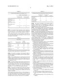
[0101] Table 1 indicates the primary temperatures of the mild hydrocracking unit according to the prior art and according to the invention.
TABLE-US-00001 TABLE 1 Temperature of the Streams According to the Prior Art According to the Invention 1a 90 2 and 3 232 252 4a 225 -- 4b 243 238 5a 391 386 5b 414 6a 422 6f, 7a, and 12 280 7c 246 181 7f 184 -- 8 57 10a 124 10b 181 226 10c 223 -- 11c 266 15d 355 15e 370 18a 270 18b 136 208 18c 65 132 18d -- 65 19a 336 19d 206 294 19f -- 210 20a 236 20b 188 207 20c 175
[0102] Table 2 indicates the number of heat exchanges of each stream of the compression loop of the mild hydrocracking unit according to the prior art and according to the invention.
TABLE-US-00002 TABLE 2 Number of Heat Exchanges in the Compression Loop Number of Heat Exchanges Process According Process According to the Prior Art to the Invention Hydrogen (Stream 10a) 2 1 High-Pressure 8 5 Hydrogen/VGO Mixture (Stream 4a) Reaction Effluent (Stream 9 7 6a) Gaseous Effluent of B-1 5 2 (Stream 7a) Total 24 15
[0103] The number of heat exchanges in the compression loop runs from 24 to 15. This makes it possible to reduce the energy consumption of the recycling compressor (Table 3).
Table 3 indicates the powers of the exchanges with utilities of the mild hydrocracking unit according to the prior art and according to the invention.
TABLE-US-00003 TABLE 3 Energy Balance Process Thermal Power Process According According (MWeq) to the Prior Art to the Invention Deviation Furnace F-1 12.2 15.1 +2.9 Furnace F-2 6.9 6.9 -- Compression of the 65.1 58.6 -6.5 Recycling.sup.(1) Furnaces F-1 + F-2 + 84.2 80.6 -3.6 Compression .sup.(1)The compression power of the recycling compressor is converted into MWeq by using the following factor: 1 MW of compression power = 4.37 MWeq of HP steam
[0104] The process according to the invention makes it possible to reduce the consumption of the recycling compressor by 6.5 MWeq.
[0105] The overall thermal power of the furnaces (F-1+F-2) is slightly higher in the process according to the invention, but overall a reduction of the hot utilities by 3.6 MW is observed, or a reduction of 4.3%.
[0106] Another advantage of the invention is the increase in the temperature of the residue at the outlet of the process so as to be sent directly into the FCC riser without preheating or cooling in advance. In the prior art, this stream should be heated by 4° C. (or 0.9 MW) before going to the riser.
[0107] The process according to the invention also makes it possible to reduce the cost of the exchangers using the reduction of the number of high-pressure calendars and the total number of calendars.
Table 4 indicates the number and the cost of the exchangers of the mild hydrocracking unit according to the prior art and according to the invention. Only the exchangers having heat exchanges between streams of the process are considered.
TABLE-US-00004 TABLE 4 Exchangers Having Heat Exchanges Between Streams of the Process According to the According to the Prior Art Invention Deviation Total Number of 20 17 -3 Exchangers Number of High- 14 9 -5 Pressure Exchangers Cost of Installed 44.2 36.9 -7.3 Exchangers (M$)
[0108] The process according to the invention makes it possible to reduce the cost of exchangers by 7.3 M$, or a reduction of 16% of the cost of the exchangers having heat exchanges between streams of the process.
[0109] The preceding examples can be repeated with similar success by substituting the generically or specifically described reactants and/or operating conditions of this invention for those used in the preceding examples.
[0110] From the foregoing description, one skilled in the art can easily ascertain the essential characteristics of this invention and, without departing from the spirit and scope thereof, can make various changes and modifications of the invention to adapt it to various usages and conditions.
User Contributions:
Comment about this patent or add new information about this topic:
Images included with this patent application:
 |  |
 |  |
 |
| Similar patent applications: | |
| Date | Title |
|---|---|
| 2015-04-23 | Catalyst for the hydrotreatment of a heavy hydrocarbon feedstock |
| 2015-04-30 | Compounds and methods for inhibiting corrosion in hydrocarbon processing units |
| 2015-04-30 | Methods for treating hydrocarbon streams containing mercaptan compounds |
| 2015-04-30 | Method for dewaxing hydrocarbon oil and method for producing lubricating-oil base oil |
| 2015-04-16 | Mesoporous fcc catalysts with excellent attrition resistance |
| New patent applications from these inventors: | |
| Date | Title |
|---|---|
| 2016-05-26 | Method and plant for redox chemical looping combustion of a solid hydrocarbon feedstock |
| 2016-02-04 | Reforming process with optimized distribution of the catalyst |
| 2015-07-16 | Catalytic cracking process allowing improved upcycling of the calories from the combustion fumes |
| 2014-06-26 | Process for mild hydrocracking of heavy hydrocarbon fractions with optimized thermal integration for the purpose of reducing greenhouse gas emissions |
| Top Inventors for class "Mineral oils: processes and products" | |
| Rank | Inventor's name |
|---|---|
| 1 | Omer Refa Koseoglu |
| 2 | Scott Lee Wellington |
| 3 | Abdennour Bourane |
| 4 | Alakananda Bhattacharyya |
| 5 | Beckay J. Mezza |