Patent application title: PORTABLE ELECTRICAL POWER SOURCE
Inventors:
Chih-Chen Lai (New Taipei, TW)
Chih-Chen Lai (New Taipei, TW)
IPC8 Class: AH02J700FI
USPC Class:
320103
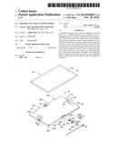
Class name: Electricity: battery or capacitor charging or discharging one cell or battery charges another
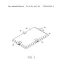
Publication date: 2014-11-20
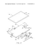
Patent application number: 20140340021
Abstract:
A portable electrical power source configured to provide power for a
portable electronic device includes a base, a chargeable battery, a
connector, and at least one locking structure. The base includes a first
surface and a second surface facing away from the first surface. The base
defines a receiving room between the first surface and the second surface
and at least one cavity. The chargeable battery is received in the
receiving room. The locking structures are rotatably received in the
cavities to lock the portable electronic device onto the first surface of
the base. The connector is positioned on the first surface and is
electrically connected to the chargeable battery and the portable
electronic device. The chargeable battery charges the portable electronic
device through the connector.Claims:
1. A portable electrical power source configured to provide power for a
portable electronic device, the portable electrical power source
comprising: a base comprising a first surface and a second surface facing
away from the first surface, the base defining a receiving room between
the first surface and the second surface, and at least one cavity; a
chargeable battery received in the receiving room; at least one locking
structure rotatabley received in the at least one cavity and configured
for locking the portable electronic device onto the first surface of the
base; and a connector positioned on the first surface and electrically
connected to the chargeable battery, the connector configured to
electrically connected to the portable electronic device, the chargeable
battery charging the portable electronic device through the connector.
2. The portable electrical power source of claim 1, wherein the base comprises a power button, when the power button is pressed, the portable electronic device is charged by the portable electrical power source, when the portable electronic device is pressed again, the portable electrical power source stop charging the portable electronic device.
3. The portable electrical power source of claim 2, wherein the base comprises power indicator configured to display the amount of power remaining in the chargeable battery.
4. The portable electrical power source of claim 3, wherein both the power button and the power indicator are positioned on the second surface.
5. The portable electrical power source of claim 1, wherein the base comprises a bottom surface connected between the first surface and the second surface, the base comprises a supporting substrate extending upward from an end of the first surface adjacent to the bottom surface, and the supporting substrate defines a receiving cavity for receiving the connector.
6. The portable electrical power source of claim 5, wherein the receiving cavity comprises a first receiving cavity and a second receiving cavity communicating with the first receiving cavity, the connector comprises a supporting portion and a connecting portion connected to the supporting portion, the supporting portion is completely received in the second receiving cavity, one end of the connecting portion is fixedly connected to the supporting portion and is received in the first receiving cavity, the other end of the connecting portion extends out of the first receiving cavity.
7. The portable electrical power source of claim 6, wherein a height of the supporting portion is shorter than a height of the second receiving cavity, and the supporting portion is capable of moving in the second receiving cavity to adjust a position of the connector with respect to the supporting substrate.
8. The portable electrical power source of claim 5, wherein each locking structure comprises a locking portion, a torsion spring and a fixed pole, the locking portion is rectangular, and each of the locking portions is rotatably received in the cavity by the torsion spring and the fixed pole.
9. The portable electrical power source of claim 8, wherein the cavity is rectangular and comprises three sidewalls, the three sidewalls of each cavity defines a blind hole, a first through hole aligning with the blind hole, and a first receiving hole, one end of each of the locking portions defines a third receiving cavity, the third receiving cavity is rectangular, and comprises three internal sidewalls, each of the three internal sidewalls of the third receiving cavity defines a second through hole corresponding to the blind hole, a second receiving hole corresponding to the first receiving hole, and a third through hole corresponding to the first through hole, the first through hole runs through the bottom surface, one end of the torsion spring is inserted into the second receiving hole and the other end of the torsion spring is inserted into the first receiving hole, one end of the fixed pole runs through the first through hole, the torsion spring is received in the blind hole.
10. The portable electrical power source of claim 9, wherein one end of the first through hole in the bottom surface forms internal threads, the fixed pole comprises external threads formed on formed on an end of it, a length of the fixed pole is equal to a distance between the bottom surface and a bottom of the blind hole, and the external threads engage with the internal threads of the first through hole.
11. The portable electrical power source of claim 8, wherein each of the locking structures comprises a plastic plate positioned on an internal sidewall of the locking portion.
12. The portable electrical power source of claim 5, wherein the base comprises a top surface facing away from the bottom surface, and two opposite sidewalls connected between the first surface and the second surface, each of the top surface and the two opposite sidewalls defines a cavity, and the number of the locking structure corresponds to the number of the cavity.
13. The portable electrical power source of claim 12, wherein the base comprises a first charging port for charging the chargeable battery.
14. The portable electrical power source of claim 13, wherein the first charging port is positioned on the top surface.
Description:
BACKGROUND
[0001] 1. Technical Field
[0002] The present disclosure relates to a portable electrical power source.
[0003] 2. Description of Related Art
[0004] Portable communication transceivers, such as mobile phones, are ubiquitous. In many instances, it is desirable to provide a visual display on the communications transceiver to supply the operator with a visual message or graphical image. The drawback is that the visual displays require relatively high electrical power, which causes the batteries to be depleted quickly.
[0005] Therefore, it is desirable to provide a portable electrical power source that can overcome the above-mentioned limitations.
BRIEF DESCRIPTION OF THE DRAWINGS
[0006] Many aspects of the present disclosure can be better understood with reference to the following drawings. The components in the drawings are not necessarily drawn to scale, the emphasis instead being placed upon clearly illustrating the principles of the present disclosure.
[0007] FIG. 1 is an assembled, isometric view of a portable electrical power source in accordance with an exemplary embodiment.
[0008] FIG. 2 is an exploded, isometric view of the portable electrical power source of FIG. 1.
[0009] FIG. 3 is a cross-sectional view taken along line III-III of FIG. 2.
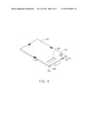
[0010] FIG. 4 is similar to FIG. 1, but viewed from another angle.
DETAILED DESCRIPTION
[0011] FIGS. 1-4 show a portable electrical power source 10 configured to provide power for a portable electronic device according to an embodiment. In the embodiment, the electronic device is a mobile phone 20. The mobile phone 20 is rectangular and includes a lower surface 21. The mobile phone 20 also includes a charging port 21a positioned at the lower surface 21.
[0012] The power source 10 includes a base 100, a connector 112, a chargeable battery 170, three locking structures 30, and various circuits (not shown).
[0013] The base 100 is substantially rectangular and includes a first surface 110, a second surface 120 facing away from the first surface 110, a top surface 130, a bottom surface 140 facing away from the top surface 130, and two opposite sidewalls 150. The first surface 110 is substantially parallel to the second surface 120. The top surface 130 is substantially parallel to the bottom surface 140. Both the top surface 130 and the bottom surface 140 are perpendicularly connected between the first surface 110 and the second surface 120. The two opposite sidewalls 150 are substantially parallel to each other and are perpendicularly connected between the first surface 110 and the second surface 120. The base 10 defines a receiving room 160 between the first surface 110 and the second surface 120 for receiving the chargeable battery 170 and the various circuits.
[0014] The base 10 also includes a supporting substrate 111 perpendicularly extending upward from an end of the first surface 110 adjacent to the bottom surface 140. The supporting substrate 111 defines a receiving cavity 180. The receiving cavity 180 includes a first receiving cavity 180a and a second receiving cavity 180b communicating with the first receiving cavity 180a.
[0015] The connector 112 includes a supporting portion 112a and a connecting portion 112b connected to the supporting portion 112a. A shape and size of the connecting portion 112b match a shape and size of the charging port 21a of the mobile phone 20. The supporting portion 112a is completely received in the second receiving cavity 180b. One end of the connecting portion 112b is fixedly connected to the supporting portion 112a and is received in the first receiving cavity 180a. The other end of the connecting portion 112b extends out of the first receiving cavity 180a.
[0016] In the embodiment, a height of the supporting portion 112a is shorter than a height of the second receiving cavity 180b, such that the supporting portion 112a is capable of moving up and down in the second receiving cavity 180b to adjust a position of the connector 112 with respect to the supporting substrate 111.
[0017] The top surface 130 and the two sidewalls 150 each define a cavity 151. Shapes and sizes of the three cavities 151 are the same. The cavities 151 are rectangular. Two opposite internal sidewalls of each cavity 151 defines a blind hole 152 and a first through hole 154 aligning with the blind hole 152. The first through hole 154 runs through the bottom surface 140. An end of the first through hole 154 in the bottom surface 140 forms internal threads (not shown). A vertical surface 15a perpendicularly connected between the two opposite internal sidewalls of the cavity 151 defines a first receiving hole 153.
[0018] The three locking structures 30 cooperatively lock the mobile phone 20 onto the first surface 110. Each of the locking structures 30 includes a locking portion 200, a torsion spring 300, and a fixed pole 400.
[0019] The locking portion 200 is rectangular. Each of the locking structures 30 also includes a plastic plate 210 positioned on an internal sidewall of the locking portion 200.
[0020] Each of the locking portions 200 is rotatably received in the cavity 151 by the torsion spring 300 and the fixed pole 400. One end of each of the locking portions 200 defines a third receiving cavity 220. The third receiving cavity 220 is also rectangular and includes three internal sidewalls. Each of the internal sidewalls defines a second through hole 221 corresponding to the blind hole 152, a second receiving hole 222 corresponding to the first receiving hole 153, and a third through hole 223 corresponding to the first through hole 154. A length of the fixed pole 400 is equal to a distance between the bottom surface 140 and a bottom of the blind hole 152. As such, the fixed pole 400 is completely received in the base 10. The fixed pole 400 includes external threads 401 on an end of it.
[0021] In assembly, the torsion spring 300 is received in the third receiving cavity 220 with one end of the torsion spring 300 inserted into the second receiving hole 222 and the other end inserted into the first receiving hole 153. The fixed pole 400 is inserted through the first through hole 154 and the torsion spring 300 is received in the blind hole 152 with the external threads 401 engaging with the internal threads of the first through hole 154. Therefore, the locking portions 200 are partly and rotatably received in the cavities 151.
[0022] In the embodiment, the base 100 also includes a power button 121 and a power indicator 122. Both the power button 121 and the power indicator 122 are positioned on the second surface 120. The power button 121 controls the charging of the mobile phone 20. When the power button 121 is pressed, the mobile phone 20 is charged by the portable electrical power source 10. When the power button 121 is pressed again, the portable electrical power source 10 stops charging the mobile phone 20. The power indicator 122 displays the amount of power remaining in the chargeable battery 170.
[0023] In the embodiment, the base 100 also includes a first charging port 141 connected to an external power source (not shown) for charging the chargeable battery 170. The first charging port 141 is positioned on the bottom surface 140.
[0024] The various circuits are configured to electrically connect the connector 112, the first charging port 141, the power button 121, the power indicator 122, and the chargeable battery 170 together.
[0025] In use, the locking portions 200 are bent outward from the first surface 110. The mobile phone 20 is pushed along a passage defined by the two locking portions 200 positioned on the two opposite sidewalls 150. Then, the three locking portions 200 are bent back toward the first surface 110, and the mobile phone 20 is securely fastened by the plastic plates 210, such that the connector 112 is received in the charging port 21a of the mobile phone 20. Pressing the power button 121 charges the mobile phone 20 through the connector 112.
[0026] When the mobile phone 20 is finished charging, pressing the power button 121 again stops the portable electrical power source 10 from charging the mobile phone 20.
[0027] It is noteworthy that, in alternative embodiments, the first charging port 141 can be positioned on the second surface 120 or on the top surface 130. The power button 121 can be positioned on an end of the second surface 120 adjacent to the top surface 130, and the base 100 can define any number of cavities 151 with corresponding locking structures 30.
[0028] It will be understood that the above particular embodiments are shown and described by way of illustration only. The principles and the features of the present disclosure may be employed in various and numerous embodiment thereof without departing from the scope of the disclosure as claimed. The above-described embodiments illustrate the possible scope of the disclosure but do not restrict the scope of the disclosure.
User Contributions:
Comment about this patent or add new information about this topic:
| People who visited this patent also read: | |
| Patent application number | Title |
|---|---|
| 20140338852 | TREATED INORGANIC PIGMENTS HAVING IMPROVED DISPERSABILITY AND USE THEREOF IN PAPER PRODUCTS |
| 20140338851 | WATER-DISPERSIBLE PAPER |
| 20140338850 | ASPHALT EMULSIONS, PRODUCTS MADE FROM ASPHALT EMULSIONS, AND PROCESSES FOR MAKING FIBROUS MATS FROM ASPHALT EMULSIONS |
| 20140338849 | PAPER PRODUCT AND A METHOD AND A SYSTEM FOR MANUFACTURING FURNISH |
| 20140338848 | PANEL HANGING SYSTEM |
Images included with this patent application:
 |  |
 |  |
 |
| Similar patent applications: | |
| Date | Title |
|---|---|
| 2013-09-19 | Portable power supply |
| 2014-12-11 | Wireless power transmission apparatus for high efficiency energy charging |
| 2014-12-04 | Non-contact power transmission device |
| 2014-12-11 | Reducing conversion losses and minimizing load via appliance level distributed storage |
| 2011-05-12 | Portable terminal |
| New patent applications in this class: | |
| Date | Title |
|---|---|
| 2019-05-16 | Casing-type charging module for mobile device |
| 2019-05-16 | Battery apparatus and cell balancing circuits |
| 2018-01-25 | Charger for a portable battery powered device and a mobile phone case |
| 2016-12-29 | Fuel cell system |
| 2016-07-14 | Charger with an energy storage element |
| New patent applications from these inventors: | |
| Date | Title |
|---|---|
| 2016-06-30 | Illuminating device |
| 2015-11-12 | Method for manufacturing led die |
| 2015-10-01 | Optical fiber connector with optical fiber holder received in rj45 plug |
| 2015-08-27 | Optical communication module and method for assembling same |
| 2015-08-13 | Method for adjusting circuit board |
| Top Inventors for class "Electricity: battery or capacitor charging or discharging" | |
| Rank | Inventor's name |
|---|---|
| 1 | Shinji Ichikawa |
| 2 | Guoxing Li |
| 3 | Chun-Kil Jung |
| 4 | Juergen Mack |
| 5 | Nam Yun Kim |