Patent application title: STRUCTURING OF THE OGIVE SURFACE OF A PROJECTILE
Inventors:
Hannes Dikhoff (Oberasbach, DE)
Karlheinz Muss (Hochstadt, DE)
Vasile Papet (Furth, DE)
Frank Mönius (Cadolzburg, DE)
Assignees:
RUAG AMMOTEC GMBH
IPC8 Class: AF42B1202FI
USPC Class:
102501
Class name: Ammunition and explosives projectiles
Publication date: 2014-10-30
Patent application number: 20140318405
Abstract:
The invention relates to a projectile with a projectile tip (9) at the
front as viewed in the direction of the shot, which transforms via an
ogive (1) into a rear cylindrical area (7). To reduce the air resistance
and optimize precision, it is proposed according to the invention that
the surface of the ogive (1) be structured.Claims:
1. A projectile with a projectile tip at the front as seen in the
direction of firing, developing into a rear cylindrical region by way of
an ogive, characterized in that the surface of the ogive is structured.
2. The projectile according to claim 1, characterized in that the surface has recesses.
3. The projectile according to claim 2, characterized in that the recesses have a droplet shape.
4. The projectile according to claim 2, characterized in that the recesses are arranged on circles, which encompass the ogive and are arranged at a right angle to the longitudinal axis of the projectile.
5. The projectile according to claim 4, characterized in that the recesses are arranged so they abut against one another on the circles.
6. The projectile according to claim 4, characterized in that the recesses on one circle are arranged with an offset from the recesses on a neighboring circle, so that a recess on one circle is arranged between two recesses on a neighboring circle.
7. The projectile according to claim 6, characterized in that the recesses are one circle are arranged with an offset from the recesses on the neighboring circle amounting to half of the diameter of a recess.
8. The projectile according to claim 4, characterized in that four circles are arranged on the ogive.
9. The projectile according to claim 4, characterized in that peripheral grooves on the cylindrical region are arranged beneath the recesses in the direction away from the projectile tip and run parallel to the circles.
10. The projectile according to claim 1, characterized in that the surface of the projectile tip is designed to be smooth and a calming zone whose surface is smooth is arranged beneath the recesses in the direction away from the projectile tip up to the grooves.
11. A use of a projectile claim 1 for cartridges of the caliber 0.22 LR, in particular for rim-fire cartridges.
Description:
[0001] The invention relates to a projectile having a projectile tip at
the front, as seen in the direction of firing, which develops into a rear
cylindrical area by way of an ogive.
[0002] Cartridges of the 0.22 LR caliber currently have a projectile with an ogive, whose surface is designed to be smooth without exception. The shape of the ogive represents an attempt to improve the trajectory properties of the projectile.
[0003] The object of the invention is to develop a projectile according to the preamble of claim 1, which will have a lower air resistance and an optimized precision.
[0004] This object is achieved according to the invention by the fact that the surface of the ogive is structured. It has surprisingly been found that even minor structuring of the surface will reduce the air resistance and optimize the precision of the projectile.
[0005] In a preferred embodiment, the surface has recesses. Recesses are easily created.
[0006] In a preferred embodiment, the recesses are droplet-shaped. The special droplet shape of the recesses on the ogive produces positive changes in the air resistance of the projectile. This leads to an elongated and more uniform trajectory and thus improves the precision.
[0007] The recesses are preferably arranged on circles, which encompass the ogive and are arranged perpendicular to the longitudinal axis of the projectile, wherein the recesses are preferably arranged so they abut against one another on the circles. The recesses are then arranged so that the resulting air turbulence is added and subtracted, so that an optimal flow resistance coefficient Cw value is achieved.
[0008] This situation can be further improved if the recesses are arranged so they are also on a circle in relation to the recesses on a neighboring circle, so that one recess is arranged on the circle between two recesses on a neighboring circle.
[0009] This can be further improved if the recesses on one circle are arranged so they are offset from the recesses on a neighboring circle, so that a recess on one circle is arranged between two recesses on a neighboring circle.
[0010] The optimum approach is when the recesses on one circle are arranged with an offset from the recesses on the neighboring circle, amounting to half the diameter of one recesses. This embodiment is illustrated in the figures, which are described below.
[0011] Four circles are preferably provided on the ogive.
[0012] In a preferred embodiment, peripheral grooves running parallel to the circles are arranged on the cylindrical area beneath the recesses in the direction away from the tip of the projectile. The grooves in the cylindrical area have the task of optimally deflecting the air stream, which is generated by the droplet-shaped recesses around the projectile. The projectile is therefore also much less sensitive to weather influences such as wind and rain or snow.
[0013] In a preferred embodiment, the surface of the tip of the projectile is designed to be smooth, and a calming zone is arranged beneath the recesses in the direction away from the tip of the projectile as far as the grooves, where the surface of this calming zone is smooth. Turbulence develops in these regions. There is a calming effect on the air flow due to their smooth surfaces.
[0014] The use of the projectile according to the invention for cartridges of the caliber 0.22 LR is preferred, in particular for rim-fire cartridges.
[0015] The invention is explained in greater detail below on the basis of two figures.
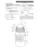
[0016] FIG. 1 shows a projectile according to the invention having a projectile tip 9, which develops into a cylindrical region 7 by way of an ogive 1. Recesses 2 are arranged on the surface of the ogive as structuring.
[0017] These recesses 2 are droplet shaped, so that the largest diameter 5 is in the lower half of the droplet shape, i.e., it is situated away from the projectile tip 9. Starting from the tip of the droplet, which points in the direction of the projectile tip 9, the diameter of the droplet shape increases steadily up to the largest diameter 5 and then decreases steadily.
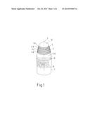
[0018] These recesses 2 are arranged on circles 4a, 4b, 4c, 4d (see FIGS. 2a and 2b in this regard), which encompass the ogive 1 and are arranged at a right angle to the longitudinal axis 3 of the projectile. Recesses 2 in the embodiment shown here are arranged so they abut against one another on these circles 4a, 4b, 4c, 4d. The recesses 2 are arranged on a circle 4b with an offset in relation to the recesses 2 on a neighboring circle 4a or 4c, so that a recess 2 on a circle 4a, 4b, 4c, 4d is arranged between two recesses 2 on a neighboring circle 4a, 4b, 4c, 4d. The recesses 2 on a circle 4a, 4b, 4c, 4d are preferably arranged with an offset from the recesses 2 on the neighboring circle 4a, 4b, 4c, 4d, so the offset amounts to half of the diameter 5 (see FIG. 2b) of a recess 2. The diameter 5 of the recess 2 refers to the width of the recess 2 on the surface.
[0019] FIG. 2a shows schematically the circles 4a, 4b, 4c, 4d on the ogive 1 on which the recesses 2 are arranged. It can be seen here well that the recesses 2 are arranged on a circle 4a, 4b, 4c, 4d, so that they are offset radially from the recesses 2 on the neighboring circle 4a, 4b, 4c, 4d. The recesses 2 in FIG. 2a have a droplet-shaped design.
[0020] Grooves 8 running parallel to the circles 4a, 4b, 4c, 4d are arranged on the cylindrical region 7 below the recesses 2 in the direction away from the projectile tip 9.
[0021] The air resistance of the basic projectile is altered in a positive sense due to the special droplet shape of the recesses 2 on the ogive 1 of the projectile. This leads to an elongated and more uniform trajectory and therefore improved precision. The recesses 2 are arranged in such a way that the resulting turbulence can be added and subtracted, thus achieving an optimal Cw value.
[0022] The grooves 8 situated in the cylindrical region 7 are designed so that they optimally deflect the air stream, which is created due to the droplet-shaped recesses 2, around the projectile. This makes the projectile much less sensitive to weather influences such as wind or rain and snow.
[0023] The region in which the turbulence occurs is defined so that the projectile tip 9 is smooth, i.e., it has no recesses there and there is a calming zone 10 between the recesses 2 and the grooves 8, having a smooth surface and contributing toward the calming of the air flow.
User Contributions:
Comment about this patent or add new information about this topic:
| People who visited this patent also read: | |
| Patent application number | Title |
|---|---|
| 20170146124 | Cover for an Access Opening |
| 20170146123 | TRANSMISSION PARK CONTROL WITH INTEGRATED BRAKE FUNCTION |
| 20170146122 | GEAR ACTUATOR FOR DUAL CLUTCH TRANSMISSION |
| 20170146121 | HYDRAULIC CONTROL DEVICE FOR AUTOMATIC TRANSMISSION |
| 20170146120 | SHIFT DEVICE OF DUAL CLUTCH TRANSMISSION |
Images included with this patent application:
 |  |
 |
| Similar patent applications: | |
| Date | Title |
|---|---|
| 2014-12-18 | Thermal shock tube and the process of production thereof |
| 2014-12-25 | Spin-stabilized non-lethal projectile with a shear-thinning fluid |
| 2014-12-25 | High volume multiple component projectile assembly |
| 2014-11-06 | Frangible projectile |
| 2010-12-09 | Guided projectile |
| New patent applications in this class: | |
| Date | Title |
|---|---|
| 2016-06-02 | Projectile with enhanced ballistics |
| 2016-05-12 | Biological active bullets, systems, and methods |
| 2016-03-31 | Muzzleloader systems |
| 2016-02-18 | Material based impact reactive projectiles |
| 2016-02-04 | Steerable munitions projectile |
| New patent applications from these inventors: | |
| Date | Title |
|---|---|
| 2011-02-24 | Ignition charge |
| Top Inventors for class "Ammunition and explosives" | |
| Rank | Inventor's name |
|---|---|
| 1 | Jahangir S. Rastegar |
| 2 | Eric Scheid |
| 3 | Richard T. Murray |
| 4 | Enrico R. Mutascio |
| 5 | Edward W. Sheridan |