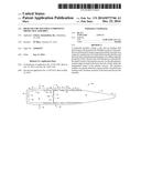
Patent application title: HIGH VOLUME MULTIPLE COMPONENT PROJECTILE ASSEMBLY
Inventors:
Pj Marx (Sarasota, FL, US)
Pj Marx (Sarasota, FL, US)
IPC8 Class: AF42B1402FI
USPC Class:
102526
Class name: Composite rifling or driving means (e.g., band) including annular member
Publication date: 2014-12-25
Patent application number: 20140373746
Abstract:
A projectile includes a head, a tail, and an interface that interconnects
the head and tail. Multiple sections of the interface are deformed by
being compressed radially inwardly into respective annular recesses
formed between the interface and the head and tail during manufacturing
or by rifling when the projectile is fired. The amount of deformation is
controlled by the depth of each of the annular recesses. In all
embodiments, annular ridges formed in the head, the tail, or both, define
the longitudinal extent of the annular recesses. The interface includes
an annular obturation region and has a beveled open leading end to
facilitate insertion of the head and tail into the interface.Claims:
1. A projectile, comprising: a head, a tail, and an interface that
interconnects the head and tail; at least one annular recess formed
between said interface and said head and tail, each recess of said at
least one annular recess having a preselected depth; said interface
having at least one section that is deformed a preselected amount by
being compressed radially inwardly; said preselected amount of
deformation being controlled by the preselected depth of each of the
annular recesses.
2. The projectile of claim 1, further comprising: the longitudinal extent of the annular recesses being defined by annular ridges formed in the head, the tail, or both the head and tail.
3. The projectile of claim 1, further comprising: said interface including an annular obturation region.
4. The projectile of claim 3, further comprising: said interface having a beveled open leading end to facilitate insertion of the head and tail into the interface.
5. The projectile of claim 1, further comprising: said at least one recess being formed between the interface and the head and tail during manufacturing of the projectile.
6. The projectile of claim 1, further comprising: said at least one recess being formed between the interface and the head and tail by rifling when the projectile is fired.
7. A projectile, comprising: a head, a tail, and an interface that interconnects said head and said tail; a diameter-reducing annular step of predetermined depth formed in said head; said interface having an open leading end, a closed trailing end, an exterior surface, and a cavity defined by an interior surface; a diameter-increasing annular step formed in said interior surface of said interface, said diameter-increasing annular step increasing the diameter of said cavity; said diameter-increasing annular step creating an annular space between a predetermined extent of said tail and said interface; said exterior surface of said interface having a flat trailing end, a uniform diameter mid-section, a trailing section that extends from said flat trailing end to said uniform diameter mid-section and which gradually increases in diameter; said annular obturation region formed where said trailing section and said uniform diameter mid-section merge with one another; a leading end of said interface abutting said diameter-reducing annular step when said projectile is assembled, said leading end of said interface having a thickness equal to said predetermined depth of said diameter-reducing annular step so that an exterior surface of said head and an exterior surface of said interface are flush with one another when said projectile is in its assembled configuration; an annular ridge of predetermined height and extent formed in a trailing end of said head, said annular ridge being a drive chamfer; and an annular recess of predetermined depth and extent formed in said head in leading relation to said drive chamfer; said interface being compressed radially inwardly at said annular recess and at said annular space; and whereby a plurality of projectiles follow a substantially common path of travel when fired sequentially because each projectile of said plurality of projectiles has an interface having a common quantity, location, annular extent, longitudinal extent and depth of compressed areas.
8. A projectile, comprising: a head, a tail, and an interface that interconnects said head and said tail; said head including a frusto-conical section extending from a leading end of said head to a point about mid-length of said head; a diameter-reducing annular step formed mid-length of said head; a first annular ridge formed in said head in longitudinally spaced and trailing relation to said diameter-reducing annular step; a second annular ridge formed in said head in longitudinally spaced and trailing relation to said first annular ridge; a first annular recess formed between said interface and said head that extends from said diameter-reducing annular step to said first annular ridge; said first annular recess having a predetermined depth and extent; a second annular recess formed between said interface and said head that extends from said first annular ridge to said second annular ridge; said second annular recess having a predetermined depth and extent; a third annular recess formed between said interface and said head that extends from said second annular ridge to a trailing end of said head; said third annular recess having a predetermined depth and extent; an annular ridge formed in a leading end of said tail. said interface having an open leading end, a closed trailing end, an exterior surface, and a cavity defined by an interior surface; said closed trailing end having a flat exterior bottom wall and a flat interior bottom wall; an annular diameter-increasing step formed in said interior surface of said interface about mid-length of a tail-receiving section of said interface; a fourth annular recess formed between said interface and said tail that extends from said annular ridge formed in said leading end of said tail to said annular diameter-increasing step formed in said interior surface of said interface; and said fourth annular recess having a predetermined depth and extent.
9. The projectile of claim 8, further comprising: said exterior surface of said interface having a flat trailing end, a uniform diameter mid-section, a trailing section that extends from said flat trailing end to said uniform diameter mid-section and which gradually increases in diameter, and an annular obturation region formed where said trailing section and said uniform diameter mid-section merge with one another.
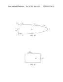
10. The projectile of claim 9, further comprising: said head having a flat trailing wall disposed in abutting relation to said leading end of said tail; a concavity formed in a leading wall of said tail; a protuberance formed in said flat trailing wall of said head, said protuberance fitting into said concavity; whereby there is no need to remove said protuberance during manufacturing of the projectile.
11. The projectile of claim 10, further comprising: said interface having first, second, third and fourth annular sections thereof compressed radially inwardly by rifling when said projectile is fired so that said annular sections are respectively disposed in said first, second, third and fourth annular recesses so that each of said annular sections are deformed to conform to the contour of said head and tail; said deformations being positioned on the leading side of said obturation region; said deformations being advantageous because the depth and extent of deformation is controlled by the predetermined depth and extent of each of said annular recesses.
12. The projectile of claim 8, further comprising: a concavity formed in a flat leading end of said tail; said concavity formed by a mirror image protuberance at the leading end of a ram that drives said tail into said die.
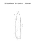
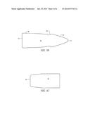
13. A projectile, comprising: a head, a tail, and an interface that interconnects said head and said tail; said head having a leading end and a trailing end; said head including a frusto-conical section extending from said leading end of said head to an annular point about one-third the distance from said leading end of said head to said trailing end of said head; a diameter-reducing annular step of predetermined depth formed in said head at said annular point; a leading end of said interface abutting said diameter-reducing annular step when said projectile is assembled, said leading end of said interface having a thickness equal to said predetermined depth of said diameter-reducing annular step so that an exterior surface of said head and an exterior surface of said interface are flush with one another when said projectile is in its assembled configuration; an annular ridge of predetermined height and extent formed in a trailing end of said head, said annular ridge being a drive chamfer; and an annular recess of predetermined depth and extent formed in said head in leading relation to said drive chamfer.
14. The projectile of claim 13, further comprising: said interface being compressed into said annular recess during assembly of said projectile.
15. The projectile of claim 13, further comprising: said interface being compressed into said annular recess during firing of said projectile.
16. The projectile of claim 13, further comprising: said interface having an open leading end, a closed trailing end, an exterior surface, and a cavity defined by an interior surface; said closed trailing end having a flat exterior bottom wall and a flat interior bottom wall; an annular diameter-increasing step formed in said interior surface of said interface about mid-length of a tail-receiving section of said interface; an annular recess extending from said annular diameter-increasing step to said leading end of said tail to facilitate insertion of said tail into said interface; said exterior surface of said interface having a flat trailing end, a uniform diameter mid-section having a diameter greater than a diameter of said flat trailing end, and a trailing section that extends from said flat trailing end to said uniform diameter mid-section; an annular obturation band of predetermined longitudinal extent formed where said trailing section and said uniform diameter mid-section merge with one another.
17. The projectile of claim 13, further comprising: said head having a flat trailing wall disposed in abutting relation to a leading wall of said tail; a concavity formed in said leading wall of said tail, said concavity formed by a mirror image protuberance at the leading end of a ram that drives said tail into said die; a protuberance formed in said flat trailing wall of said head, said protuberance fitting into said concavity; whereby said protuberance need not be removed during manufacturing of the projectile.
18. The projectile of claim 13, further comprising: said interface having first and second annular sections thereof deformed radially inwardly by rifling when said projectile is fired so that said annular sections are respectively disposed in said annular recess formed in said head and in said annular recess formed in said tail so that each of said annular sections are deformed to conform to the contour of said head and tail; said deformations being positioned on the leading side of said obturation region; said deformations being advantageous because the depth and extent of deformation is controlled by said predetermined depth and extent of said annular recesses.
19. A projectile, comprising: a head, a tail, and an interface that interconnects said head and said tail; said head having a leading end and a trailing end; said head including a frusto-conical section extending from said leading end of said head to an annular point about one-third the distance from said leading end of said head to said trailing end of said head; a diameter-reducing annular step of predetermined depth formed in said head at said annular point; a leading end of said interface abutting said diameter-reducing annular step when said projectile is assembled, said leading end of said interface having a thickness equal to said predetermined depth of said diameter-reducing annular step so that an exterior surface of said head and an exterior surface of said interface are flush with one another when said projectile is in its assembled configuration; an annular ridge of predetermined height and extent formed in a trailing end of said head, said annular ridge being a drive chamfer; and an annular recess of predetermined longitudinal extent and depth formed in said head in leading relation to said drive chamfer, said annular recess extending to said diameter-reducing annular step and gradually reducing in depth as it approaches said diameter-reducing annular step.
20. The projectile of claim 19, further comprising: said interface being compressed into said annular recess during assembly of said projectile.
21. The projectile of claim 19, further comprising: said interface being compressed into said annular recess during firing of said projectile.
22. The projectile of claim 19, further comprising: said interface having an open leading end, a closed trailing end, an exterior surface, and a cavity defined by an interior surface; said closed trailing end having a flat exterior bottom wall and a flat interior bottom wall; an annular diameter-increasing step formed in said interior surface of said interface about mid-length of a tail-receiving section of said interface; an annular recess extending from said annular diameter-increasing step to said leading end of said tail to facilitate insertion of said tail into said interface.
23. The projectile of claim 19, further comprising: said exterior surface of said interface having a flat trailing end, a uniform diameter mid-section having a diameter greater than a diameter of said flat trailing end, and a trailing section that extends from said flat trailing end to said uniform diameter mid-section; an annular obturation band of predetermined extent disposed where said trailing section merges with said uniform diameter mid-section.
24. The projectile of claim 19, further comprising: said head having a flat trailing wall disposed in abutting relation to a leading wall of said tail; a concavity formed in said leading wall of said tail; a protuberance formed in said flat trailing wall of said head, said protuberance fitting into said concavity; whereby said protuberance need not be removed during manufacturing of the projectile.
25. The projectile of claim 19, further comprising: said interface having first and second annular sections thereof compressed radially inwardly by rifling when said projectile is fired so that said annular sections are respectively disposed in said annular recess formed in said head and in said annular recess formed in said tail so that each of said annular sections are deformed to conform to the contour of said head and tail; said deformations being positioned on the leading side of said obturation region; said deformations being advantageous because the depth and extent of deformation is controlled by said predetermined depth and extent of said annular recesses.
Description:
BACKGROUND OF THE INVENTION
[0001] 1. Field of the Invention
[0002] This invention relates to ammunition. More specifically, it relates to a projectile that is advantageously deformed by rifling.
[0003] 2. Brief Description of the Related Art
[0004] Projectiles that include a head and a tail held together by an interface have enhanced performance characteristics relative to conventional projectiles.
[0005] However, the rifling in a gun barrel causes compression of the interface and the number of such compressions, as well as the location, depth and longitudinal extent of the compression is essentially uncontrollable, thereby reducing the effectiveness of the projectile. Accordingly, multiple projectiles fired in sequence will follow differing paths of travel due to the random quantity, location, depth and extent of the compressions formed in the interface.
[0006] The conventional wisdom is that such compression is a natural consequence of rifling and that nothing can be done about it.
[0007] In view of the art considered as a whole at the time the present invention was made, it was not obvious to those of ordinary skill in the field of this invention that the effects of random rifling compressions could be reduced or eliminated. Thus it was not obvious how such effects could be reduced or eliminated.
BRIEF SUMMARY OF THE INVENTION
[0008] The long-standing but heretofore unfulfilled need for a projectile that is not subject to the limitations of prior art projectiles is now met by a new, useful, and nonobvious invention.
[0009] In all embodiments, the novel structure includes a head, a tail, and an interface that interconnects the head and tail.
[0010] In a first embodiment, the head includes a frusto-conical section that extends from a leading end of the head to a point about mid-length of the head. A diameter-reducing annular step is formed about mid-length of the head.
[0011] The depth of the diameter-reducing annular step is equal to the thickness of the leading edge of the interface so that the leading edge of the interface abuts the diameter-reducing annular step and an exterior surface of the interface is flush with an exterior surface of the head.
[0012] A first annular ridge is formed in the head in trailing, longitudinally spaced apart relation to the diameter-reducing annular step. Accordingly, a first annular recess extends longitudinally from the diameter-reducing annular step to the first annular ridge.
[0013] A second annular ridge is formed in the head in trailing and longitudinally spaced apart relation to the first annular ridge, forming a second annular recess between the interface and the head that extends from the first annular ridge to the second annular ridge.
[0014] A third annular recess extends from the second annular ridge to the trailing edge of the head.
[0015] A third annular ridge is formed in a leading end of the tail.
[0016] The interface has an open leading end, a closed trailing end, an exterior surface, and a cavity defined by an interior surface. The closed trailing end has a flat exterior bottom wall and a flat interior bottom wall. An annular diameter-increasing step is formed in the interior surface of the interface about mid-length of a tail-receiving section of the interface.
[0017] Accordingly, a fourth annular recess is formed between the interface and the tail, extending from the third annular ridge to the annular diameter-increasing step formed in the interior surface of the interface.
[0018] The interface has first, second, third and fourth annular sections that are compressed radially inwardly during manufacturing or by rifling when the projectile is fired so that said annular sections are respectively disposed in the first, second, third and fourth annular recesses so that each of the annular sections of the interface are deformed to conform to the contour of said head and tail.
[0019] All of the deformations are positioned on the leading side of the annular obturation region. The deformations are advantageous because the amount of deformation is controlled by the depth of each of the annular recesses and the longitudinal extent of each of the annular recesses. Moreover, the quantity and location of each deformation is also under the control of the projectile manufacturer. This is in sharp contrast with the deformations of the prior art that are random in number, location, depth and extent and which therefore produce random flight paths for projectiles fired in sequence.
[0020] In a second embodiment, only one annular recess and one annular ridge is formed in the head. The annular ridge is formed in the trailing end of the head and the annular recess is formed in the head in leading relation to the annular ridge and in longitudinally spaced apart relation to the annular diameter-reducing step formed in the head. In this embodiment, the annular diameter-reducing step is formed in the head about one-third the distance from its leading end to its trailing end.
[0021] In the second embodiment, as in the first embodiment, an annular recess extends from the annular diameter-increasing step formed in the interior surface of the interface to the leading end of the tail. This annular recess extends about half the length of the tail.
[0022] A third embodiment is similar to the second because it includes one annular recess and one annular ridge formed in the head. The annular ridge is formed in the trailing end of the head as in the second embodiment but the annular recess formed in the head in leading relation to the annular ridge extends to the annular diameter-reducing step formed in the head, reducing gradually in depth as it approaches said annular diameter-reducing step. As in the second embodiment, the annular diameter-reducing step is formed in the head about one-third the distance from the leading end of the head to its trailing end.
[0023] In the third embodiment, as in the second embodiment, a second annular recess extends from the annular diameter-increasing step formed in the interior surface of the interface to the trailing wall of the head, i.e., to the annular ridge formed in the trailing end of the head.
[0024] In all embodiments, the exterior surface of the interface has a flat trailing end, a uniform diameter mid-section, and an open leading end that reduces slightly in diameter relative to the mid-section. The diameter of the mid-section is also slightly greater than the diameter of the trailing end. This difference in diameter creates an interface transition region between the trailing end of the interface and the uniform diameter mid-section.
[0025] An annular inflection or obturation region is formed in the interface transition region.
[0026] The open leading end of the interface has a beveled edge that guides the tail into the cavity of the interface when the tail is dropped into the cavity. Therefore there is no need for a time-consuming precise alignment between the open end of the interface and the tail. The trailing end of the tail is in spaced apart relation to the flat bottom wall of interface cavity when the tail is dropped into the interface cavity.
[0027] A ram has a frusto-conical cavity that matches the slope of the frusto-conical section of the head. The head and tail are pushed into the interface by the ram until the flat trailing wall of the tail abuts the flat interior bottom wall of the interface.
[0028] A radially inward crimp is formed in the open leading end of the interface after the tail and head have been inserted into the cavity of the interface. The crimp abuts the diameter-reducing step formed in the head.
[0029] In all embodiments, the interface is compressed into the annular recesses either prior to projectile firing or during such firing, there being four such annular recesses in the first embodiment and two such annular recesses in the second and third embodiments. However, since the quantity, location, depth, longitudinal extent of each annular recess is determined by the projectile manufacturer, the depressions formed in the interface are under the control of said manufacturer.
[0030] All embodiments eliminate the random number, random depth, random length, and random location of rifle-created depressions that are formed in prior art projectiles.
BRIEF DESCRIPTION OF THE DRAWINGS
[0031] For a fuller understanding of the invention, reference should be made to the following detailed description, taken in connection with the accompanying drawings, in which:
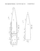
[0032] FIG. 1A is a longitudinal sectional view of a first embodiment of the novel projectile assembly;
[0033] FIG. 1B is a longitudinal sectional view of the projectile head of the first embodiment;
[0034] FIG. 1C is a longitudinal sectional view of the projectile tail of the first embodiment;
[0035] FIG. 1D is a longitudinal sectional view of the interface prior to assembly;
[0036] FIG. 1E is a longitudinal sectional view of the interface after assembly;
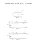
[0037] FIG. 2A is a longitudinal sectional view of a second embodiment of the novel projectile assembly;
[0038] FIG. 2B is a longitudinal sectional view of the projectile head of the second embodiment;
[0039] FIG. 2C is a longitudinal sectional view of the projectile tail of the second embodiment;
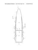
[0040] FIG. 3A is a longitudinal sectional view of a third embodiment of the novel projectile assembly;
[0041] FIG. 3B is a longitudinal sectional view of the projectile head of the second embodiment; and
[0042] FIG. 3C is a longitudinal sectional view of the projectile tail of the third embodiment.
DETAILED DESCRIPTION OF THE PREFERRED EMBODIMENT
[0043] A first embodiment of the novel structure is denoted as a whole in FIG. 1A by the reference numeral 10a.
[0044] Structure 10a includes head 12, tail 32, and interface 48. Head 12 is depicted individually in FIG. 1B, tail 32 is depicted individually in FIG. 1C, and interface 48 is depicted individually in FIGS. 4A and 4B.
[0045] Leading end 14 of head 12 can be flat as depicted, rounded, or pointed. Frusto-conical section 16 extends from leading end 14 to a point about mid-length the length of said head. Diameter-reducing annular step 18 is formed at said location and the diameter of head 12 is reduced from said step 18 to the trailing end of said head. The reduced diameter increases slightly but linearly as at 20 from said annular step 18 to first transversely disposed annular ridge 22. The diameter of head 12 is uniform from first ridge 22 to second transversely disposed annular ridge 24 and is again uniform until it reaches flat trailing wall 30.
[0046] The leading end of interface 48 abuts diameter-reducing annular step 18 and an interior surface of said interface is spaced apart from head 12 by the first and second transversely disposed annular ridges 22 and 24, thereby creating first, second and third annular recesses 20, 26 and 28.
[0047] Three annular recesses are thus created between interface 48 and head 12, said three spaces being denoted 20, 26, and 28.
[0048] Tail 32, depicted in side elevation in FIGS. 1A and 1C, is preferably, for manufacturing purposes, a wire that is cold formed by being punched into a die cavity. The exterior surface of tail 32 therefore conforms to the shape of the die cavity. Tail 32 includes flat trailing wall 34, transition region 36 where its diameter increases slightly, uniform diameter section 38, and leading wall 40. The tail diameter increases at annular ridge 42 at the leading end of said tail.
[0049] Central concavity 44 formed in flat leading wall 40 is formed by a mirror image protuberance at the leading end of a ram that drives tail 32 into its die.
[0050] FIG. 1B depicts head 12 of the first embodiment. It is preferably machined on a lathe although any other suitable manufacturing means is within the scope of this invention.
[0051] FIG. 1D depicts interface 48 prior to assembly and FIG. 1E depicts interface 48 after assembly, i.e., as it appears in FIG. 1A.
[0052] Interface 48 is cold formed by positioning a flat coin over a die having a cavity formed therein and by punching the coin into said cavity with a ram. The contour of the cavity determines the exterior shape of interface 48 and the contour of the ram determines the interior shape of interface 48.
[0053] The bottom wall of the cavity is flat, thereby forming flat exterior trailing end 50 and the leading end of the ram is flat, thereby forming interior flat bottom wall 58. The diameter of the cavity has its most narrow dimension at said bottom wall. A cavity diameter transition region is provided where the interior and exterior diameter of the cavity increases slightly as it extends away from said bottom wall, thereby forming interface transition region 52 in the exterior surface of interface 48. The diameter of the cavity is uniform from the opening of the cavity to said cavity diameter transition region, thereby forming uniform diameter region 54 of said interface.
[0054] The annular inflection point that marks the transition from increasing diameter section 52 to uniform diameter section 54 is indicated by confronting arrows 56 in FIGS. 1D and 1E. This annular region is known in the industry as the obturation point, band, or region.
[0055] The leading end of the ram is flat so that it forms flat interior surface 58 as aforesaid. The contour of the leading end of the ram produces curved interior surface 60 and an increase in diameter at a location away from its flat leading end produces annular diameter-increasing step 62 in the interior surface of interface 48.
[0056] An annular recess is thus created between interface 48 and tail 32, said annular recess being denoted 38 in FIG. 1A. This is the fourth annular recess in the first embodiment of the novel assembly and it extends from annular ridge 42 formed in tail 32 to said annular diameter-increasing step 62.
[0057] Thus, in the embodiment of FIG. 1A, there are four annular recesses formed between interface 48, head 12 and tail 32 with three of the four being between the interface and head 12.
[0058] As best understood in connection with FIG. 1D, the undepicted ram has a uniform diameter towards its leading end relative to annular step 62 to produce uniform diameter section 54 in interface 48. The ram then increases in diameter linearly to produce linearly diverging section 66 at the leading, open end of interface 48.
[0059] The open leading end of interface 48 is beveled as at 68 (FIGS. 1D and 1E). The bevel helps guide tail 32 into the hollow interior or cavity of interface 48 when said tail is dropped thereinto. More particularly, after interface 48 has been cold-formed from a flat coin at a first station by the punch and die, it is displaced by a conveyor or other suitable means to a second station where tail 32 is dropped thereinto from an overhead bowl or other device. Thus there is no need for a time-consuming precise alignment between the open end of interface 48 and tail 32.
[0060] Trailing end 34 of tail 32 will not abut flat bottom wall 58 of interface 48 when said tail 32 is dropped into said interface. Head 12 is dropped into the interface after tail 32 and flat trailing wall 30 of head 12 abuts leading wall 40 of tail 32 as depicted. An undepicted protuberance formed in the trailing wall 30 of head 12 fits into concavity 44. This eliminates the need to remove said protuberance.
[0061] The undepicted ram having a frusto-conical cavity that matches the slope of frusto-conical section 16 of head 12 pushes head 12 and tail 32 into interface 48 until flat trailing wall 34 of tail 32 abuts flat bottom wall 58 of interface 48. Interface 48 is then crimped at its open leading end so that it assumes its FIG. 1A and FIG. 1E configuration.
[0062] As depicted in FIG. 1A, the above-disclosed contours create transversely disposed annular recesses 20, 26, 28, and 38 when head 12 and tail 32 are fully received within interface 48. Interface 48 is compressed radially inwardly by rifling when the projectile is fired so that it occupies each of said annular recesses. The radially inward compression may also be made during the manufacturing process. All compressions/deformations of interface 48 are on the leading side of obturation region 56. This compression is advantageous because it is a controlled deformation, as distinguished from a prior art random, uncontrolled deformation. The result is a projectile that more consistently hits its aiming point.
[0063] Referring now to the second embodiment, depicted in FIGS. 2A-C, instead of three (3) annular recesses between head 12 and interface 48 as in the first embodiment, there is but one (1) annular recess, denoted 70, formed in head 12 Annular recess 70 is formed in head 12 in leading relation to drive chamfer 74 which is provided in the form of an annular raised ridge formed in the trailing end of head 12, in trailing relation to annular recess 70. Drive chamfer 74 imparts spin to head 12.
[0064] In this second embodiment, interface 48 is pre-compressed radially inwardly into annular recess 70 during assembly as indicated by directional arrows 72. The compression is produced by a cannelure die that also produces a bullet knurl with symmetrically arranged pronged teeth. A wheel die would deform the bullet shape.
[0065] In this second embodiment, annular diameter-reducing step 18 is formed in head 12 about one-third of the way from its flat leading end 14 to its flat trailing end 30. As in the first embodiment, the leading end of interface 48 has a thickness equal to the depth of step 18 so that an exterior surface of head 12 is flush with an exterior surface of interface 48.
[0066] The internal diameter of interface 48 in this second embodiment increases at diameter increasing step 62 so that annular recess 76 is created between said interface and tail 32. Annular recess 76 facilitates projectile assembly by reducing friction during such assembly. After assembly, radially inwardly directed arrows 78 indicate that interface 48 is compressed into annular recess 76. The compression may be accomplished during the assembly step after tail 32 is inserted into the cavity of interface 48, or the compression may take place during firing of the round.
[0067] Obturation band 54 is denoted with a bracket to indicate its length. As in the first embodiment, the function of obturation band 54 is to seal against gas pressure leakage.
[0068] The length of obturation band 54 in inches for a copper interface 48 is calculated by dividing one thousand pounds per square inch by 500 to produce a first length such as two inches, and by dividing one thousand pounds per square inch by fifteen hundred to produce a second length such as two-thirds of an inch. The length of obturation band 54 for a copper interface is thus about one and one-third inch, beginning about two-thirds of an inch from flat trailing wall 50 of interface 48 to a point about one and one-third inch in a leading direction therefrom, i.e., to where annular interstitial space 76 begins.
[0069] Head 12 of this second embodiment is individually depicted in FIG. 2B and tail 32 is individually depicted in FIG. 2C.
[0070] The third embodiment is depicted in FIGS. 3A-3C. It includes one annular recess 80 and one annular ridge 82 formed in head 12, said annular ridge 82 serving as a driving chamfer Annular ridge 82 is formed in the trailing end of head 12 as in the second embodiment but annular recess 80 formed in head 12 in leading relation to annular ridge 82 extends to or almost to annular diameter-reducing step 18 formed in head 12. As in the second embodiment, annular diameter-reducing step 18 is formed in head 12 about one-third the distance from the leading end of the head to its trailing end. The depth of annular recess 80 gradually reduces as it approaches annular diameter-reducing step 18.
[0071] Second annular recess 84 extends from annular diameter-increasing step 62 formed in the interior surface of interface 48 to the leading end of tail 32, i.e., to annular ridge 82 formed in the trailing end of head 12.
[0072] Head 12 of this third embodiment is individually depicted in FIG. 3B and tail 32 is individually depicted in FIG. 3C.
[0073] It will be seen that the advantages set forth above, and those made apparent from the foregoing description, are efficiently attained. Since certain changes may be made in the above construction without departing from the scope of the invention, it is intended that all matters contained in the foregoing description or shown in the accompanying drawings shall be interpreted as illustrative and not in a limiting sense.
User Contributions:
Comment about this patent or add new information about this topic:

