Patent application title: DISTRIBUTION PLATE IN ELECTROLYTE BATH
Inventors:
David Mertens (De Pinte, BE)
Dominiek Seynaeve (Harelbeke/hulste, BE)
Assignees:
NV BEKAERT SA
IPC8 Class: AC25D508FI
USPC Class:
204273
Class name: Electrolytic cells with agitator
Publication date: 2014-06-12
Patent application number: 20140158528
Abstract:
An installation (20) for continuously electroplating a plurality of
elongated metal elements (21, 21', 21'') with another metal comprises a
bath (22) of an electrolyte wherein the elongated metal elements (21,
21', 21'') are travelling. The bath (22) comprises a collector space (24)
positioned under the elongated metal elements (21, 21', 21'') and the
bath further comprises a distribution plate (26) between the collector
space (24) and the elongated metal elements (21, 21', 21''). The
installation (20) further comprises a pump (25) for circulating the
electrolyte in the bath (22) from the collector space (24) through the
distribution plate (26). The collector space (24) causes first flow
losses to the flow of the electrolyte. The distribution plate (26) has a
multiplicity of openings for allowing the flow of the electrolyte and
these openings cause second flow losses to the flow of the electrolyte.
Each of the second flow losses is at least five times greater than the
first flow losses.Claims:
1.-8. (canceled)
9. An installation for continuously electroplating a plurality of elongated metal elements with another metal, said installation comprising: a plurality of elongated metal elements to be plated, said plurality of elongated metal elements functioning as cathodes; a bath of an electrolyte wherein said elongated metal elements are immersed and are travelling along a rectilinear path; said bath comprising a collector space positioned under said elongated metal elements; said bath comprising an anode; said bath further comprising a distribution plate between said collector space and said elongated metal elements; said distribution plate having a multiplicity of openings for allowing flow of an electrolyte; a pump for circulating said electrolyte in said bath from said collector space through said distribution plate.
10. An installation according to claim 9, said collector space causing first flow losses to the flow of said electrolyte; said openings in said distribution plate causing second flow losses to the flow of said electrolyte, each of said second flow losses being at least five times greater than said first flow losses.
11. An installation according to claim 10, wherein said collector space has a first average cross-section for allowing the flow of said electrolyte, wherein said openings of said distribution plate have a second cross-section, said second cross-section being at least one three times smaller than said first cross-section.
12. An installation according to claim 11, wherein said elongated metal elements are steel wires or steel cords and wherein said another metal is selected of the group consisting of zinc, tin, nickel, copper, or alloys thereof
13. An installation according to claim 9, wherein said distribution plate is different from said anode.
14. An installation according to claim 9, wherein said distribution plate is a flat plate.
15. An installation according to claim 9, wherein there are more than forty elongated metal elements running parallel to each other.
16. An installation according to claim 9, wherein said pump is located at one side of said plurality of elongated elements.
Description:
TECHNICAL FIELD
[0001] The present invention relates to an installation for continuously electroplating a plurality of elongated metal elements with another metal.
BACKGROUND ART
[0002] Installations for continuously electroplating a plurality of elongated metal elements with another metal are widely known and used in the art.
[0003] For example, EP-A1-0 297 178 of applicant, discloses an installation for electroplating a plurality of steel wires. The steel wires function as cathode and a soluble anode provides the metal to be coated on the steel wires.
[0004] As a matter of another example, U.S. Pat. No. 5,478,457 discloses an apparatus for the continuous electrolytic plating of wire-shaped objects. The wires follow a zigzag path of travel past a succession of anodes and cathodes. There is sliding contact between the cathodes and the wires. The anodes may have channel-shaped recesses through which the wires are running. Holes are made in the bottom of the anodes to allow flow of the electrolyte.
[0005] GB-A-2 067 223 and US-Al -2002/0011419 disclose an electro-deposition apparatus for electroplating a film on a single planar substrate.
[0006] There is a general trend in the art to increase the number of elongated metal elements to be plated from twenty to thirty-six, forty, and even more. This large-scale mass production allows to reduce the investment and maintenance cost per elongated element.
[0007] However, there are also drawbacks associated with the increased number of metal elements. Indeed, it has become a real challenge to obtain an equal and homogeneous coating on all the elongated elements. An equal coating means that all the elongated elements have the same average thickness of coating or the same weight of the other metal. A homogeneous coating means that there is no thickness variation in the coating over the circumference of the elongated elements.
[0008] The problem is complex and complexity increases with increasing number of elongated elements. Various parameters are supposed to play a role.
[0009] There is the type of anode: soluble or inert anode. The form and dimensions can play a part. If soluble, also the amount of anodes can play a part.
[0010] There is the type of electrolyte and the concentration of the electrolyte.
[0011] There is the flow of the electrolyte through the bath: homogeneous, laminar, presence or absence of turbulences, . . .
[0012] There is the current density.
[0013] There is the position of the pumps circulating the electrolyte. Indeed, the position of the pumps at one side of the installation is not symmetric and is expected to negatively influence the eventual coating weight on the elongated elements. An elongated element running close to the pump experiences another electrolyte flow than an elongated element running most remote from the pump.
[0014] As the elongated elements function as cathodes, the voltage level on the elongated elements, or better, the absence of differences thereof, may influence the eventual coating weight on the elongated elements.
DISCLOSURE OF INVENTION
[0015] It is an object of the invention to avoid the drawbacks of the prior art.
[0016] It is another object of the invention to reduce the differences in coating weight over the plurality of elongated metal elements.
[0017] It is also an object of the invention to avoid displacing the pumps for circulating the electrolyte.
[0018] According to the invention, there is provided an installation for continuously electroplating a plurality of elongated metal elements with another metal. The installation comprises a plurality of elongated metal elements to be plated. The elongated metal elements function as cathodes. The installation further comprises a bath of an electrolyte wherein the elongated metal elements are immersed and are travelling, one adjacent and parallel to another one, along a rectilinear path. The bath comprises a collector space positioned under the elongated metal elements for receiving the electrolyte. The bath further comprises an anode and a distribution plate between the collector space and the elongated metal elements. The distribution plate has a multiplicity of openings for allowing flow of an electrolyte. The installation has a pump for circulating the electrolyte in the bath in a direction from the collector space through the distribution plate to the elongated metal elements.
[0019] The collector space causes first flow losses to the flow of the electrolyte. The distribution plate has a multiplicity of openings for allowing the flow of the electrolyte. These openings in the distribution plate cause second flow losses to the flow of the electrolyte. Each of the second flow losses through the distributor plate are at least five times, preferably more than ten times, most preferably more than hundred times, greater than the first flow losses in the collector space.
[0020] One way to determine the degree and amount of flow losses is to control the velocity or speed of the electrolyte, amongst others by the cross-section. Indeed according to Darcy's law, the flow losses are proportional to the square value of the average speed of the liquid. According to the same law, the flow losses are inversely proportional to the hydraulic diameter of the medium. With a given value of the pump height, the speed of the liquid is higher for a small cross-section than for a big cross-section.
[0021] The collector space has a first cross-section for allowing the flow of the electrolyte and the distribution plate has a multiplicity of openings allowing the flow of the electrolyte from the collector space towards the elongated elements.
[0022] The openings in the distribution plate have a second cross-section which is at least three times, and preferably at least ten times, and most preferably much more times, smaller than the first cross-section.
[0023] The functioning of the invention will be further explained with reference to the drawings, particularly with reference to FIGS. 2 and 3.
[0024] The elongated metal elements may be steel wires, steel cords, steel strands, steel strips or steel ropes.
[0025] The other metal to be coated on the elongated metal elements may be zinc, tin, nickel, copper, or alloys thereof. Noble metals such as gold, silver, platinum are not excluded either.
[0026] The elongated metal elements function as cathode, the electrical charge is transmitted to the elongated metal elements through driving or guiding rolls or wheels which are negatively charged.
[0027] The number of elongated metal elements running in parallel to each other and to be coated simultaneously can vary from twenty to forty and more.
[0028] The distribution plate is different from the anode.
[0029] The distribution plate is preferably a flat plate and does not provide channel like structures for each separate elongated element.
[0030] Due to the functioning of the distribution plate, there is no need to relocate the pump, e.g. somewhat centrally under the bath. A central location under the bath will make repair and maintenance of the pump more cumbersome.
BRIEF DESCRIPTION OF FIGURES IN THE DRAWINGS
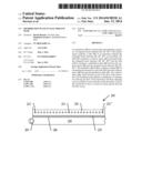
[0031] FIG. 1 is a cross-section of an installation according to the prior art.
[0032] FIG. 2 is a cross-section of an electroplating installation according to the invention.
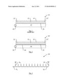
[0033] FIG. 3 is an electrical scheme used to explain in another way the functioning of the distribution plate.
MODE(S) FOR CARRYING OUT THE INVENTION
[0034] FIG. 1 illustrates the working of an installation 10 for electroplating steel wires 12 according to the prior art.
[0035] Steel wires 12 run parallel and rectilinear with respect to each other in an electrolyte bath 14. An anode 16, soluble or not, is installed under the wires 12. The steel wires function as cathode. Ions leave the anode 16 and travel through the electrolyte towards the negatively loaded steel wires 12.
[0036] A collector space 17 is arranged below the anode 16. A circulation pump 18 circulates electrolyte from the collector space 17 over or through the anode 16 towards the steel wires 12 and the surface of the electrolyte bath 14. An amount of electrolyte is overflowing the bath 14 at upstream and downstream side and is recuperated (not shown).
[0037] As the circulation pump 18 is located at one side of the installation, the flow of the electrolyte in the neighbourhood of the steel wires 12' which are close to the pump 18 may be completely different than the flow of the electrolyte in the neighbourhood of the steel wires 12'' which are most remote from the pump 18. The inventors have noticed that these differences may negatively influence the homogeneity and equality of coating on the steel wires 12. After having discovered this, the challenge was to make as uniform as possible the flow of electrolyte around each and every steel wire 12, 12',12''.
[0038] FIG. 2 illustrates an electroplating installation 20 according to the invention.
[0039] Steel wires 21 run parallel to each other in an electrolyte bath 22. An anode 23, soluble or not, is installed under the wires 21. The steel wires 21 function as cathode. Ions leave the anode 23 and travel through the electrolyte towards the negatively loaded steel wires 21.
[0040] A collector space 24 is arranged below the anode 23. A circulation pump 25 circulates electrolyte from the collector space 24 over or through the anode 23 towards the steel wires 21 and the surface of the electrolyte bath 22. An amount of electrolyte is overflowing the bath 22 at upstream and downstream side and is recuperated (not shown).
[0041] The main difference with the prior art installation 10 is the presence of a distribution plate 26, different from the anode 23, located between the collector space 24 and the anode 23. This distribution plate 26 has a plurality of small openings which present a high resistance to the electrolyte flowing through. The flow losses of the electrolyte through the openings of the distribution plate are so high in comparison with the flow losses of the electrolyte in the collector space 24 that the losses of the electrolyte in the collector space 24 can be neglected.
[0042] The main principle of this functioning is explained again in FIG. 3. FIG. 3 depicts an electrical scheme 30 with a lot of electrical resistors 32 in series. The resistors 32 represent the flow losses of the electrolyte in the collector space 24. The resistors 32 have all a low resistance Rc. Spread over the series of resistors 32 there are branches with resistors 34. The resistors 34 represent the flow losses of the electrolyte in each opening of the distributor plate 26 and have a high resistance Rh, which is much higher than Rc, for example more than hundred times higher, more than thousand times higher.
[0043] The total electrical resistance going from the left side of electrical scheme 30 towards left upper point 36' is almost the same as the total electrical resistance going from the left side of the electrical scheme 30 towards right upper point 36''. The reason is that the values of the electrical resistances Rc are to be neglected in comparison with values of the electrical resistances Rh.
[0044] Returning back to FIG. 2, the electrolyte reaches wire 21', which is closest to the pump 25, "in the same way" as it reaches wire 21, in the middle of the installation, and "in the same way" as it reaches wire 21'', most remote from the pump 25. The reason is that the flow losses of the electrolyte over the collector space 24 are to be neglected in comparison with the flow losses through the openings of the distributor plate 26.
[0045] As already mentioned low losses in the collector space 24 are realized by having a relatively great cross-section. Having a smooth inner surface may also contribute to reduce the losses. Smooth transitions from the pump to the collector space 24 may avoid turbulences and also reduce the amount of flow losses.
[0046] In comparison with the prior art, the total losses of the electrolyte flow from the pump to the elongated elements may be higher due to the presence of the distributor plate. As a result, a higher pump height may be necessary.
[0047] The distribution plate 26 may be made of any material chemically resistant against the used chemicals in the electrolyte.
[0048] The distribution plate may have a thickness varying from 1 mm to 30 mm, e.g. from 2 mm to 20 mm.
[0049] Any type of opening (square, rectangular, circular, hexagonal . . . ) can be used. If circular the openings in the distribution plate may have a diameter varying between 3 mm to 20 mm diameter.
[0050] The invention can be practiced for soluble and non-soluble anodes and for various types of metal and for electrolytes. In contrast with the distribution plate 26, the anode is made of an electrically conductive material such as stainless steel.
EXAMPLE
[0051] A distribution plate is applied to a copper plating installation of forty steel wires. The electrolyte can be copper-citrate, copper-amine, copper-tartrate, copper-sulfate, copper-pyrophosphate, copper fluoroborate or copper cyanide.
[0052] The anode is formed by a soluble copper anode lying on a supporting plate. The cathode current density varies between 1 and 20 A/dm2. The speed of the steel wires may vary between 10 m/min and 150 m/min.
[0053] Test Results
[0054] The variation of coating weight between wires, defined as
( maximum coating weight - minimum coating weight ) average coating weight ##EQU00001##
[0055] is typically reduced with 1%.
LIST OF REFERENCE NUMBERS
[0056] 10 electroplating installation according to the prior art
[0057] 12, 12', 12'' steel wires
[0058] 14 electrolyte bath
[0059] 16 anode
[0060] 17 collector space
[0061] 18 circulation pump
[0062] 20 electroplating installation according to the invention
[0063] 21, 21', 21'' steel wires
[0064] 22 electrolyte bath
[0065] 23 anode
[0066] 24 collector space
[0067] 25 circulation pump
[0068] 26 distribution plate
[0069] 30 electrical scheme
[0070] 32 collector space resistance Rc
[0071] 34 distribution plate hole resistance Rh
[0072] 36' left upper point
[0073] 36'' right upper point
User Contributions:
Comment about this patent or add new information about this topic:
| People who visited this patent also read: | |
| Patent application number | Title |
|---|---|
| 20210223349 | DETECTION DEVICE AND METHOD FOR AUDIO DIRECTION ORIENTATION AND AUDIO PROCESSING SYSTEM |
| 20210223348 | METHOD FOR CONTROLLING THE ORIENTATION OF A SOLAR TRACKER BASED ON CARTOGRAPHIC MODELS |
| 20210223347 | METHOD FOR CONTROLLING THE ORIENTATION OF A SOLAR TRACKER BASED ON CARTOGRAPHIC MODELS |
| 20210223346 | METHOD AND APPARATUS FOR HIGH VALUE MAGNETIC RESONANCE IMAGING |
| 20210223345 | SYSTEM AND METHODS FOR T1 AND T2 WEIGHTED MAGNETIC RESONANCE IMAGING |
Images included with this patent application:
 |  |
| Similar patent applications: | |
| Date | Title |
|---|---|
| 2014-11-27 | Systems and methods for separating metallic and nonmetallic particles in a mixed-particle suspension |
| 2014-11-27 | Systems and methods for separating metallic and nonmetallic particles in a mixed-particle suspension |
| 2014-10-30 | Macromolecule positioning by electrical potential |
| 2014-11-13 | Stable photoelectrode surfaces and methods |
| 2014-11-20 | Method for producing dense thin films by electrophoresis |
| New patent applications in this class: | |
| Date | Title |
|---|---|
| 2016-05-19 | Substrate plating device |
| 2015-12-24 | Substrate electrolytic processing apparatus and paddle for use in such substrate electrolytic processing apparatus |
| 2014-09-11 | Etching device for the electrolytic etching of copper |
| 2014-03-27 | Apparatus for generating fine bubbles having a positive charge and water treatment apparatus using same |
| 2013-12-19 | Apparatus for fluid processing a workpiece |
| New patent applications from these inventors: | |
| Date | Title |
|---|---|
| 2011-09-15 | Longitudinal belt with reinforcing fibres |
| Top Inventors for class "Chemistry: electrical and wave energy" | |
| Rank | Inventor's name |
|---|---|
| 1 | Vamsee K. Pamula |
| 2 | Michael G. Pollack |
| 3 | Adam Heller |
| 4 | Vijay Srinivasan |
| 5 | Li-Shiang Liang |