Patent application title: ELECTRONIC DEVICE WITH POWER SUPPLY CONTROL MODULE
Inventors:
Wei-Kuang Liang (New Taipei, TW)
Hsien-Pin Tsou (New Taipei, TW)
Chuan-Xiang Wang (Shenzhen, CN)
IPC8 Class: AH05K706FI
USPC Class:
361728
Class name: Housing or mounting assemblies with diverse electrical components for electronic systems and devices module
Publication date: 2014-05-22
Patent application number: 20140140013
Abstract:
An electronic device includes a bottom plate, an installation board, a
circuit board, a battery, and a power supply control module. The power
supply control module includes a control member and an activating member,
and the activating member is pressed against the control member when the
electronic device is assembled. So long as the control member remains
pressed by the activating member, a flow of electrical power from the
battery to the circuit board is permitted. When the electronic device is
disassembled, the disassembly moves the activating member away from the
activating member and cuts off the power from the battery to the circuit
board, to avoid electrical short circuits or other damage that might
otherwise occur if the flow of electrical power was maintained during
disassembly.Claims:
1. An electronic device comprising: a bottom plate; an installation board
detachably secured to the bottom plate; a circuit board; a battery
electrically connected with the circuit board and located on one side of
the circuit board; and a power supply control module comprising a control
member and an activating member, the activating member protruding from
the bottom plate, and the control member is located on the circuit board;
wherein the circuit board and the battery are located between the bottom
plate and the installation board; the control member is switched on when
pressed by the activating member, and the battery provides power supply
to the circuit board; and the control member is disengaged from the
activating member and switched off when the bottom plate is detached from
the installation board to separate the activating member from the control
member, and the battery stops providing power to the circuit board.
2. The electronic device of claim 1, wherein the control member is a switch.
3. The electronic device of claim 1, wherein the activating member is substantially perpendicular to the bottom plate.
4. The electronic device of claim 1, wherein the circuit board defines a cutout adjacent to the control member, for receiving the activating member.
5. The electronic device of claim 1, wherein the control member is welded on the circuit board.
6. An electronic device comprising: a circuit board, a battery connected with the circuit board and located on one side of the circuit board; and a power supply control module comprising a control member and an activating member, wherein the control member is switched on squeezed by the activating member, and the battery provides power supply to the circuit board; the control member is disengaged from the activating member to switch off, and the battery stops providing power to the circuit board.
7. The electronic device of claim 6, further comprising a bottom plate and an installation board, wherein the activating member is protruded on the bottom plate, the control member located on the circuit board, the control member is switched on when the bottom plate is secured to the bottom plate, and the control member is switched off when the bottom plate is disengage from the bottom plate.
8. The electronic device of claim 7, wherein the control member is a switch.
9. The electronic device of claim 7, wherein the activating member is substantially perpendicular to the bottom plate.
10. The electronic device of claim 7, wherein the circuit board defines a cutout adjacent to the control member, for receiving the activating member.
11. The electronic device of claim 7, wherein the control member is welded on the circuit board.
Description:
BACKGROUND
[0001] 1. Technical Field
[0002] The present disclosure relates to electronic devices, and more particularly to an electronic device with a power supply control module.
[0003] 2. Description of Related Art
[0004] Mass-produced items such as electronic devices must be tested for all of the functions to ensure certain qualities. The electronic device needs to be disassembled and assembled repeatedly to test a printed circuit board, such as a main board. During disassembly process, tester always removes the printed circuit board when a battery provides power to the printed circuit board, thus making the printed circuit board short circuit and damaging the printed circuit board.
[0005] Therefore, there is room for improvement within the art.
BRIEF DESCRIPTION OF THE DRAWINGS
[0006] Many aspects of the embodiments can be better understood with reference to the following drawings. The components in the drawings are not necessarily drawn to scale, the emphasis instead being placed upon clearly illustrating the principles of the embodiments. Moreover, in the drawings, like reference numerals designate corresponding parts throughout the several views.
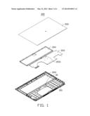
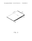
[0007] FIG. 1 is an exploded, isometric view of a electronic device in accordance with an embodiment.
[0008] FIG. 2 is similar to FIG. 1, but viewed from a different aspect.
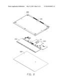
[0009] FIG. 3 is an assembled view of the electronic device of FIG. 1.
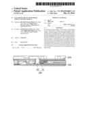
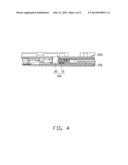
[0010] FIG. 4 is a cross-sectional view of the electronic device, taken along the line IV-IV of FIG. 3.
DETAILED DESCRIPTION
[0011] The disclosure is illustrated by way of example and not by way of limitation in the figures of the accompanying drawings in which like references indicate similar elements. It should be noted that references to "an" or "one" embodiment in this disclosure are not necessarily to the same embodiment, and such references mean "at least one."
[0012] Referring to FIG. 1, an electronic device 200 in accordance with an embodiment includes a power supply control module 100 (shown in FIG. 4), a bottom plate 201, a circuit board 203, a battery 204, and an installation board 205. In one embodiment, the electronic device may be a portable computer, and the circuit board 203 is a main board.
[0013] Referring to FIGS. 2 and 4, the power supply control module 100 includes a control member 10 and an activating member 30. The control member 10 is located on the circuit board 203. In one embodiment, the control member 10 is a switch, and in another embodiment, the control member 10 is a protruding structure. The activating member 30 protrudes from the bottom plate 201. In one embodiment, the activating member 30 is substantially perpendicular to the bottom plate 201. The control member 10 is switched on when pressed by the activating member 30 and switched off when the activating member 30 ceases to press.
[0014] The bottom plate 201 defines a receiving slot 2011 for receiving the battery 204.
[0015] The circuit board 203 defines a cutout 2031 corresponding to the control member 10. The battery 204 is located on one side of the circuit board 203 and electrically connected with the circuit board 203 by a data bus.
[0016] FIG. 3 shows that, in assembly, the installation board 205 is secured to the bottom plate 201 in a well-known manner, such as by screw or bolt. The circuit board 203 and the battery 204 are sandwiched between the bottom plate 201 and the installation board 205, and the battery 204 is received in the receiving slot 2011. The activating member 30 is positioned on the cutout 2031, and presses the control member 10 of the circuit board 203 to switch on the control member 10. The battery 204 is thereby electrically connected to the circuit board 203 and provides power to the circuit board 203.
[0017] In disassembly, the bottom plate 201 is detached from the installation board 205 and removed from the installation board 205 to disengage the activating member 30 from the control member 10. The control member 10 is thus switched off, and the battery 204 is disconnected from the circuit board 203, to stop providing power to the circuit board 203. Thus, the circuit board 203 is protected from being damaged.
[0018] It is to be understood, however, that even though numerous characteristics and advantages have been set forth in the foregoing description of embodiments, together with details of the structures and functions of the embodiments, the disclosure is illustrative only and changes may be made in detail, especially in the matters of shape, size, and arrangement of parts within the principles of the disclosure to the full extent indicated by the broad general meaning of the terms in which the appended claims are expressed.
User Contributions:
Comment about this patent or add new information about this topic:
Images included with this patent application:
 |  |
 |  |
 |
| Similar patent applications: | |
| Date | Title |
|---|---|
| 2014-11-13 | Electronic device with rotatable stop plate |
| 2014-10-23 | Electronic device with fan module |
| 2014-11-13 | Structure and method for self protection of power device with expanded voltage ranges |
| 2014-11-13 | Electronic device assembly with compression gasket |
| 2014-11-13 | Electronic device with air duct |
| New patent applications in this class: | |
| Date | Title |
|---|---|
| 2019-05-16 | Electronic device with seal member |
| 2019-05-16 | Electronic device module |
| 2016-07-14 | Display module |
| 2016-06-16 | Power semiconductor module and power conversion device |
| 2016-06-02 | High-frequency module |
| New patent applications from these inventors: | |
| Date | Title |
|---|---|
| 2015-02-12 | Display assembly |
| 2015-01-29 | Cable tidying device and electronic device with cable tidying device |
| 2014-12-04 | Electronic device |
| 2014-10-16 | Electronic device enclosure |
| 2014-10-02 | Camera rotating structure |
| Top Inventors for class "Electricity: electrical systems and devices" | |
| Rank | Inventor's name |
|---|---|
| 1 | Zheng-Heng Sun |
| 2 | Levi A. Campbell |
| 3 | Li-Ping Chen |
| 4 | Robert E. Simons |
| 5 | Richard C. Chu |