Patent application title: Handrail Assembly
Inventors:
Ming-Fang Hsieh (Kaohsiung City, TW)
Ming-Tao Hsieh (Kaohsiung City, TW)
IPC8 Class: AE04H1714FI
USPC Class:
256 6515
Class name: Rail connection rail to rail
Publication date: 2014-04-10
Patent application number: 20140097394
Abstract:
A handrail assembly includes at least one connecting unit, and at least
two extension units each connected with the connecting unit. The
connecting unit includes a middle tube and two connecting tubes extended
from two opposite ends of the middle tube respectively. Each of the
connecting tubes has a surface formed with a plurality of elongate slits.
Each of the connecting tubes has a periphery formed with an annular
reinforcing rib to enhance resilience and fixedness of each of the
connecting tubes. Each of the extension units includes a mounting pipe
mounted on a respective one of the connecting tubes. Thus, the connecting
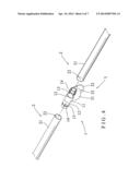
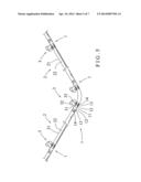
units and the extension units are detached before assembly to facilitate
and reduce the cost of storage, packaging and transportation of the
handrail assembly.Claims:
1. A handrail assembly, comprising: at least one connecting unit; and at
least two extension units each connected with the connecting unit;
wherein: the connecting unit includes a middle tube and two connecting
tubes extended from two opposite ends of the middle tube respectively;
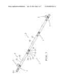
each of the connecting tubes of the connecting unit has a surface formed
with a plurality of elongate slits so that each of the connecting tubes
of the connecting unit is made resilient by the slits; each of the
extension units includes a mounting pipe mounted on a respective one of
the connecting tubes of the connecting unit; the mounting pipe of each of
the extension units has an interior formed with a mounting hole mounted
on the respective connecting tube of the connecting unit; and an outer
wall of the mounting pipe of each of the extension units and an outer
wall of the middle tube of the connecting unit are flush with each other
to form a smooth surface.
2. The handrail assembly of claim 1, further comprising at least one support unit connected with the connecting unit.
3. The handrail assembly of claim 2, wherein the support unit includes a support base connected with the middle tube of the connecting unit, and a fixing plate connected with the support base, the fixing plate of the support unit has a surface formed with a plurality of fastening holes for fastening the fixing plate of the support unit to a wall by a plurality of threaded fastening members, and the support base of the support unit has a first end connected with the middle tube of the connecting unit and a second end connected with the fixing plate.
4. The handrail assembly of claim 3, wherein the support base of the support unit has a substantially cylindrical or arcuate shape.
5. The handrail assembly of claim 2, wherein the connecting unit is made of a metallic material, each of the extension units is made of a metallic material, and the support unit is made of a metallic material.
6. The handrail assembly of claim 1, wherein each of the connecting tubes of the connecting unit has a periphery formed with an annular reinforcing rib to enhance resilience and fixedness of each of the connecting tubes.
7. The handrail assembly of claim 1, wherein the mounting pipe of each of the extension units has an outer diameter equal to that of the middle tube of the connecting unit.
8. The handrail assembly of claim 1, wherein the mounting pipes of the extension units have the same length.
9. The handrail assembly of claim 1, wherein each of the slits is extended in a longitudinal direction of each of the connecting tubes, the reinforcing rib of each of the connecting tubes traverses each of the slits, and the mounting pipe of each of the extension units is juxtaposed to the middle tube of the connecting unit.
10. The handrail assembly of claim 1, wherein the mounting pipe of one of the extension units is an angled bent pipe with different bending angles.
Description:
BACKGROUND OF THE INVENTION
[0001] 1. Field of the Invention
[0002] The present invention relates to a support device and, more particularly, to a handrail assembly.
[0003] 2. Description of the Related Art
[0004] A conventional safety handrail is usually mounted on the wall of a passageway for holding of a user to provide a safety function to older people. However, when the handrail is mounted on a longer passageway, it is necessary to provide multiple handrails which are connected together to form a longer safety handrail so that the safety handrail cannot be mounted on the wall easily and conveniently, thereby causing difficulty to the user in assembly of the safety handrail. In addition, the safety handrail cannot be detached before assembly so that the safety handrail has a larger volume, thereby causing inconvenience in and increasing the cost of storage, packaging and transportation of the safety handrail.
BRIEF SUMMARY OF THE INVENTION
[0005] In accordance with the present invention, there is provided a handrail assembly, comprising at least one connecting unit, and at least two extension units each connected with the connecting unit. The connecting unit includes a middle tube and two connecting tubes extended from two opposite ends of the middle tube respectively. Each of the connecting tubes of the connecting unit has a surface formed with a plurality of elongate slits so that each of the connecting tubes of the connecting unit is made resilient by the slits. Each of the extension units includes a mounting pipe mounted on a respective one of the connecting tubes of the connecting unit. The mounting pipe of each of the extension units has an interior formed with a mounting hole mounted on the respective connecting tube of the connecting unit. An outer wall of the mounting pipe of each of the extension units and an outer wall of the middle tube of the connecting unit are flush with each other to form a smooth surface.
[0006] The handrail assembly further comprises at least one support unit connected with the connecting unit. The support unit includes a support base connected with the middle tube of the connecting unit, and a fixing plate connected with the support base. The fixing plate of the support unit has a surface formed with a plurality of fastening holes for fastening the fixing plate of the support unit to a wall by a plurality of threaded fastening members. The support base of the support unit has a first end connected with the middle tube of the connecting unit and a second end connected with the fixing plate. The support base of the support unit has a substantially cylindrical shape. Alternatively, the support base of the support unit has a substantially arcuate shape. The connecting unit is made of a metallic material, each of the extension units is made of a metallic material, and the support unit is made of a metallic material. Each of the connecting tubes of the connecting unit has a periphery formed with an annular reinforcing rib to enhance resilience and fixedness of each of the connecting tubes. The mounting pipe of each of the extension units has an outer diameter equal to that of the middle tube of the connecting unit. Preferably, the mounting pipes of the extension units have the same length. Each of the slits is extended in a longitudinal direction of each of the connecting tubes. The reinforcing rib of each of the connecting tubes traverses each of the slits. The mounting pipe of each of the extension units is juxtaposed to the middle tube of the connecting unit. The mounting pipe of one of the extension units is an angled bent pipe with different bending angles.
[0007] The primary objective of the present invention is to provide a handrail assembly that is assembled easily and quickly.
[0008] According to the primary advantage of the present invention, the handrail assembly comprises multiple connecting units and multiple extension units connected with the connecting units step by step so that the handrail assembly is assembled easily and conveniently.
[0009] According to another advantage of the present invention, the connecting units and the extension units are detached before assembly to facilitate and reduce the cost of storage, packaging and transportation of the handrail assembly.
[0010] According to a further advantage of the present invention, each of the connecting tubes of the connecting unit is made resilient by the slits so that the mounting pipe of each of the extension units is fitted onto the respective connecting tube of the connecting unit closely and tightly.
[0011] According to a further advantage of the present invention, the reinforcing rib of each of the connecting tubes enhances resilience and fixedness of each of the connecting tubes so that each of the connecting tubes will not produce elastic fatigue easily.
[0012] Further benefits and advantages of the present invention will become apparent after a careful reading of the detailed description with appropriate reference to the accompanying drawings.
BRIEF DESCRIPTION OF THE SEVERAL VIEWS OF THE DRAWING(S)
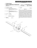
[0013] FIG. 1 is a perspective view of a handrail assembly in accordance with the preferred embodiment of the present invention.
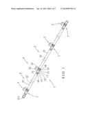
[0014] FIG. 2 is a partially exploded perspective view of the handrail assembly as shown in FIG. 1.
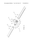
[0015] FIG. 3 is a top cross-sectional assembly view of the handrail assembly as shown in FIG. 2.
[0016] FIG. 4 is a partially exploded perspective view of a handrail assembly in accordance with another preferred embodiment of the present invention.
[0017] FIG. 5 is a partially perspective view of a handrail assembly in accordance with another preferred embodiment of the present invention.
[0018] FIG. 6 is a top cross-sectional view of the handrail assembly as shown in FIG. 5.
[0019] FIG. 7 is a partially perspective view of a handrail assembly in accordance with another preferred embodiment of the present invention.
DETAILED DESCRIPTION OF THE INVENTION
[0020] Referring to the drawings and initially to FIGS. 1-4, a handrail assembly in accordance with the present invention comprises at least one connecting unit 1, and at least two extension units 2 each connected with the connecting unit 1. In the preferred embodiment of the present invention, the handrail assembly comprises a plurality of connecting units 1, a plurality of extension units 2 connected with the connecting units 1 respectively, and a plurality of support units 3 connected with the connecting units 1 respectively.
[0021] The connecting unit 1 is made of a metallic material and includes a middle tube 11 and two connecting tubes 12 extended from two opposite ends of the middle tube 11 respectively. Each of the connecting tubes 12 of the connecting unit 1 has a surface formed with a plurality of elongate slits 13 so that each of the connecting tubes 12 of the connecting unit 1 is made resilient by the slits 13. Each of the slits 13 is extended in a longitudinal direction of each of the connecting tubes 12. Each of the connecting tubes 12 of the connecting unit 1 has a periphery formed with an annular reinforcing rib 14 to enhance resilience and fixedness of each of the connecting tubes 12 so that each of the connecting tubes 12 will not produce elastic fatigue easily. The reinforcing rib 14 of each of the connecting tubes 12 traverses each of the slits 13.
[0022] Each of the extension units 2 is made of a metallic material and includes a mounting pipe 21 mounted on a respective one of the connecting tubes 12 of the connecting unit 1. The mounting pipe 21 of each of the extension units 2 is juxtaposed to the middle tube 11 of the connecting unit 1. The mounting pipe 21 of each of the extension units 2 has an interior formed with a mounting hole 22 mounted on the respective connecting tube 12 of the connecting unit 1. The mounting pipe 21 of each of the extension units 2 has an outer diameter equal to that of the middle tube 11 of the connecting unit 1 so that an outer wall of the mounting pipe 21 of each of the extension units 2 and an outer wall of the middle tube 11 of the connecting unit 1 are flush with each other to form a smooth surface. The mounting pipes 21 of the extension units 2 have the same length. Alternatively, the mounting pipes 21 of the extension units 2 have different length. Each of the extension units 2 further includes at least one end cap 211 mounted on one end of the mounting pipe 21.
[0023] The handrail assembly further comprises at least one support unit 3 connected with the connecting unit 1. The support unit 3 is made of a metallic material and includes a support base 31 connected with the middle tube 11 of the connecting unit 1, and a fixing plate 32 connected with the support base 31. The support base 31 of the support unit 3 has a first end connected with the middle tube 11 of the connecting unit 1 and a second end connected with the fixing plate 32. In the preferred embodiment of the present invention, the support base 31 of the support unit 3 has a substantially cylindrical shape. The fixing plate 32 of the support unit 3 has a surface formed with a plurality of fastening holes 33 for fastening the fixing plate 32 of the support unit 3 to a wall by a plurality of threaded fastening members 4.
[0024] As shown in FIG. 1, the handrail assembly comprises four connecting units 1, five extension units 2 connected with the connecting units 1 respectively, and four support units 3 connected with the connecting units 1 respectively. Two outermost mounting pipes 21 may have a shorter length, and two end caps 211 are mounted on the two outermost mounting pipes 21. In such a manner, each of the connecting tubes 12 of the connecting unit 1 is made resilient by the slits 13 so that the mounting pipe 21 of each of the extension units 2 is fitted onto the respective connecting tube 12 of the connecting unit 1 closely and tightly. In addition, the reinforcing rib 14 of each of the connecting tubes 12 enhances resilience and fixedness of each of the connecting tubes 12 so that each of the connecting tubes 12 will not produce elastic fatigue easily.
[0025] As shown in FIG. 4, the support base 31 of the support unit 3 has a substantially arcuate shape.
[0026] As shown in FIGS. 5 and 6, the mounting pipe 21 of one of the extension units 2 is an angled bent pipe with different bending angles.
[0027] As shown in FIG. 7, the handrail assembly comprises four connecting units 1, five extension units 2 connected with the connecting units 1 respectively, and two support units 3 connected with the connecting units 1 respectively. Thus, the number of the support units 3 may be changed.
[0028] Accordingly, the handrail assembly comprises multiple connecting units 1 and multiple extension units 2 connected with the connecting units 1 step by step so that the handrail assembly is assembled easily and conveniently. In addition, the connecting units 1 and the extension units 2 are detached before assembly to facilitate and reduce the cost of storage, packaging and transportation of the handrail assembly. Further, each of the connecting tubes 12 of the connecting unit 1 is made resilient by the slits 13 so that the mounting pipe 21 of each of the extension units 2 is fitted onto the respective connecting tube 12 of the connecting unit 1 closely and tightly. Further, the reinforcing rib 14 of each of the connecting tubes 12 enhances resilience and fixedness of each of the connecting tubes 12 so that each of the connecting tubes 12 will not produce elastic fatigue easily.
[0029] Although the invention has been explained in relation to its preferred embodiment(s) as mentioned above, it is to be understood that many other possible modifications and variations can be made without departing from the scope of the present invention. It is, therefore, contemplated that the appended claim or claims will cover such modifications and variations that fall within the true scope of the invention.
User Contributions:
Comment about this patent or add new information about this topic:
Images included with this patent application:
 |  |
 |  |
 |  |
 |  |
| Similar patent applications: | |
| Date | Title |
|---|---|
| 2014-09-18 | Handrail apparatus for use with vehicles |
| 2011-09-29 | Railing assembly |
| 2014-02-27 | Railing assembly |
| 2014-05-08 | Handicap handrail system |
| New patent applications in this class: | |
| Date | Title |
|---|---|
| 2014-11-13 | Railing system and method of manufacture |
| Top Inventors for class "Fences" | |
| Rank | Inventor's name |
|---|---|
| 1 | Dallas James |
| 2 | Robert E. Platt |
| 3 | Gordon Duffy |
| 4 | Jason Duffy |
| 5 | Matthew Carlyle Sherstad |