Patent application title: Hydraulic Radial-piston Pump for Wind Turbines
Inventors:
Ingo Valentin (Elm Grove, WI, US)
IPC8 Class: AF04B904FI
USPC Class:
417559
Class name: Pumps expansible chamber type having pumping chamber pressure responsive distributor
Publication date: 2014-03-27
Patent application number: 20140086773
Abstract:
A hydraulic radial-piston pump transfers the wind energy of the rotor to
an adjustable hydraulic motor on ground level, driving an electric
generator with constant speed. The pump consists of piston assemblies,
located in radial direction between camshaft and housing, supported by
spherical bearings at the housing and cylindrical bearings at the
camshaft, allowing for self-adjustment of the assemblies. The radial and
axial bearings of the camshaft are pivotally mounted allowing for
self-adjustment to the housing. At least two planes with cams opposing
each other compensate the piston forces in radial direction. Preferably,
the pump has four planes symmetrically arranged around a plane between
the second and third plane, compensating the piston forces in axial
direction. The center of gravity of the rotor is located between or near
the bearings of the camshaft. The loads are supported by hydraulic
pressure fields, minimizing frictional losses and increasing longevity.Claims:
1. A radial-piston pump comprising: a housing with at least two radial
bearings spaced in axial direction, a centrally located camshaft
rotatable mounted in the radial bearings having at least one cam, at
least one piston assembly for each cam having a centerline perpendicular
to the centerline of the camshaft, comprising a cylinder valve joint
having a spherical face and mounted in the bore of the housing, a
cylinder with a piston bore and a spherical face opposing the piston bore
cooperating with the spherical face of the cylinder valve joint, and a
piston, reciprocally mounted in the piston bore having a cylindrical face
with a centerline perpendicular to the centerline of the piston
cooperating with the cylindrical cam of the camshaft providing piston
force for reciprocating the piston, said cylinder valve joint comprising
two check valves having a ring shaped outer valve plate with a face, an
inner valve plate with a face and a valve body, having an outer ring
shaped valve port and an inner valve port with opposing faces concentric
to and in fluid communication with each other for delivering and
receiving fluid to and from the piston bore, said outer valve plate and
said inner valve plate each having a spring and being moveable in axial
direction for engaging the face of the outer valve plate with said face
of the outer valve port and the face of the inner valve plate with said
face of the inner valve port,
2. A radial-piston pump comprising: a housing with at least two radial bearings spaced in axial direction, a centrally located camshaft rotatable mounted in the radial bearings having at least one cam, at least one piston assembly for each cam having a centerline in a plane perpendicular to the centerline of the camshaft, wherein said radial bearings have an inner bearing face for engaging the camshaft and an outer spherical face for mounting the bearings tiltable in bores of the housing, approximating the size and shape of the outer bearing face, allowing the bearings to adjust to misalignments and deflections of the camshaft.
3. A radial piston pump as defined in claim 2. wherein the inner and outer bearing faces are exposed to a recessed area for pressurized fluid providing hydraulic forces for reducing mechanical contact forces between camshaft and radial bearings and radial bearings and housing for improving efficiency and adjustment to compensate for misalignment and deflection.
4. A radial-piston pump comprising: a housing with at least two radial bearings and at least one axial bearing spaced in axial direction, a centrally located camshaft rotatable mounted in the radial bearings and to the axial bearing, at least one piston assembly for each cam having a centerline in a plane perpendicular to the centerline of the camshaft, wherein said axial bearing has an inner bearing face for engaging the axial face of the camshaft and an outer spherical face for mounting the bearing tilt able to an indentation of the housing approximating the size and shape of the outer bearing face, allowing the axial bearing to adjust to misalignments and deflections.
5. A radial piston pump as defined in claim 4. wherein the inner and outer bearing faces are exposed to a recessed, sealed area for pressurized fluid providing hydraulic forces for reducing mechanical contact forces between camshaft and axial bearing and axial bearing and housing for improving efficiency and adjustment to compensate for misalignment and deflection.
6. A radial-piston pump comprising: a housing with at least two radial bearings spaced in axial direction, a centrally located camshaft rotatable mounted in the radial bearings having four cams with centerlines in the plane of, parallel to and an equal number of cams concentric to each other on either side of the centerline of the camshaft, the cams being symmetrically arranged to a first plane perpendicular to the centerline of the camshaft with an equal number of cams on either side, at least one piston assembly for each cam having a centerline in a plane perpendicular to the centerline of the camshaft, cooperating with the cam of the camshaft providing piston force for reciprocating the piston, said piston forces compensate each other in the plane of the centerline of the camshaft and balancing each other at said first plane perpendicular to the centerline of the camshaft, eliminating tilting of the camshaft and the effect of piston forces at the radial bearings.
7. A radial piston pump as defined in claim 6, wherein a centrally located camshaft rotatable mounted in the radial bearings having three cams with centerlines in the plane of and parallel to the centerline of the camshaft, and two outer cams concentric to each other opposing the inner cam, at least one piston assembly for each cam having a centerline in a plane perpendicular to the centerline of the camshaft, cooperating with the cam of the camshaft providing piston force for reciprocating the piston, a first piston assembly having twice the piston face area of a second piston assembly, said first piston assembly cooperates with said inner cam and said second piston assemblies cooperate with said outer cams, said piston forces compensate each other in the plane of the centerline of the camshaft and balancing each other at the plane of said first piston assembly perpendicular to the plane of the centerline of the camshaft, eliminating tilting of the camshaft and the effects of piston forces at the radial bearings .
8. A radial-piston pump comprising: a housing with at least two radial bearings and at least one axial bearing spaced in axial direction, a centrally located camshaft rotatable mounted in the radial bearings and to the axial bearing having at least one cam, a coaxially mounted rotor for driving the camshaft , said rotor having a center of gravity acting near or between said radial bearings, said rotor having fluid flow forces in axial direction being supported by the axial bearing of the camshaft.
Description:
BACKGROUND OF THE INVENTION
[0001] 1. Technical Field
[0002] The invention relates to a hydrostatic transmission, transferring the power from the rotor of a wind turbine or other high torque-low speed applications like water turbines, to the electric generator through pressurized fluid. The transmission consists of a hydraulic radial-piston pump integrated into the rotor hub and axial-piston motor with variable displacement driving the generator with constant speed.
[0003] Currently, geared transmissions are utilized to increase the low rotational speed of the rotor to the high speed needed at the generator. The inconsistent speed of the generator requires a complex circuitry and the gear boxes have a short operational life span and cause extensive costs for maintenance and overhaul. The high weight of the rotor, nacelle, gear box and generator on top of the tower requires a heavy tower and foundation. New drivetrain systems are utilized where the rotor drives a low speed generator directly without a gear box. The turbines are significantly heavier and more costly. However, it is expected that the longer operating life, lower maintenance cost and higher efficiency outweigh the higher costs of the wind turbine.
[0004] Hydrostatic drive trains have no limited operating life and their operating parameter speed and torque can be easily controlled. However, current hydraulic pumps and motors are not scalable to wind turbines within the 1 MW-20 MW power range. The reasons are the very high forces needed to transmit the power at low speeds, requiring large size assemblies with proportionally increasing tolerances, misalignments and deformation of components while utilizing hydraulic fluids of the same viscosity. The mechanical conditions, especially at bearings, result in increased contact forces and leakage, leading high losses of energy and excessive wear.
[0005] Although advantageous in application were varying high powers are transmitted, like in heavy construction machinery, hydrostatic drivetrains are not utilized in larger wind turbines since current pump and motor concepts are not scalable to the size needed for wind turbines.
[0006] 2. Background Art
[0007] In a known radial piston motor, disclosed in U.S. Pat. No. 4,469,013, the piston/cylinder assembly, having a spherical bearing at each end of the assembly, transmitting the hydraulic piston forces from the piston to the housing and the cylinder to the driveshaft without a transverse stress on the spherical bearings and between piston and cylinder. The self-alignment prevents the tilting of highly loaded components, preventing excessive wear and leakage.
[0008] To transfer the piston forces into the driveshaft of the motor, the pump/motor concept requires a pair of rotating disks revolving around a fixed pair of rotating rings coupled with the shaft itself. The mechanism contains is space consuming, and the movement of the larger number of additional parts will reduce the gains in efficiency from the piston assembly. Two sets of bearings are required, one between shaft and rotating rings and one between the rotating rings and the motor housing. The high loads and large size of the roller bearings result in high costs, and the limited space in axial direction does not favor the use of hydrostatic rings.
[0009] The Rivo Calzoni Company produces a radial piston motor with spherical bearings on both ends of the piston assembly. The circular shaped cylinder end requires large space for the bearing in circumferential direct at the spherical cam lobe, reducing the number of piston assemblies arranged around the cam shaft and increasing the manufacturing costs.
[0010] The efficiencies, life expectancies, and scalability of hydraulic pumps and motor of prior art are insufficient to use hydrostatic drive systems for large powers at low speeds, like wind or water turbines. The low speeds of 10-40 rev/min require large displacement pumps with 40-1,500 Liter/rev (10-400 gal/rev.) for a wind turbine of 1 MW to 10 MW require large pump assemblies. The proportionally increasing manufacturing tolerances, misalignments, and deformation of components, significantly increase the contact forces and leakage due to tilting, leading to lower efficiencies and excessive wear and likely destruction.
[0011] It is therefore an object of the invention to provide a hydraulic pump suitable to transmit large powers at low speeds reliably and efficient, while reducing the cost, weight and complexity of drive systems for wind turbines of prior art.
BRIEF SUMMARY OF THE INVENTION
[0012] The present invention provides a novel hydraulic pump, integrated into the hub of the rotor of a wind turbine, with piston assemblies arranged in radial direction around the cam shaft and in a common plane. There are four sets of planes spaced in axial direction to each other to balance the piston forces in radial direction and along the centerline of the cam shaft to conceptually eliminate the bearing forces at the camshaft. The bearings are pivotally mounted in the pump housing, self-adjusting to compensate for deformation and misalignment of the housing and the cam shaft. The bearings are preferably substantially hydrostatically balanced to minimize friction, wear and forces needed for their adjustment. The bearings are also capable to compensate for the weight of the rotor assembly. The axial wind forces of the rotor are compensated by the hydraulic force of an axial hydrostatic bearing at the opposing face of the camshaft the turbine blades are attached to.
[0013] The piston assemblies are arranged in radial direction between housing and the lobe of the cam, supporting the piston forces. The cylinder is pivotally connected to a spherical, form-locked joint at the housing and the piston through a bearing, cylindrically shaped and form-locked to the lobe of the camshaft. The spherical joint of the cylinder contains check valves for ingress and egress of the hydraulic fluid.
[0014] The nearly fully hydrostatically balanced loads and forces, and the self-alignment of all moving parts significantly reduces leakage and minimizes friction and wear. The form-locked bearing mechanisms replace the function of the piston spring, reducing the friction and compression losses.
BRIEF DESCRIPTION OF THE DRAWINGS
[0015] The features of the invention which are believed to be novel are set forth with particularity in the appended claims. The invention, together with the further objects and advantages thereof, may best be understood by reference to the following description taken in conjunction with the accompanying drawings, wherein like reference numerals identify like elements, and wherein:
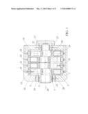
[0016] FIG. 1 is a cross section of the radial-piston pump in accordance with the invention.
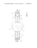
[0017] FIG. 2 is a partial cross section of opposing piston assemblies at the cam shaft.
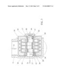
[0018] FIG. 3 is a cross section of the pump assembly, integrated into the rotor hub, depicting the balance of forces at the rotor assembly.
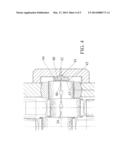
[0019] FIG. 4 is an enlarged cross section of the axial bearing of the camshaft.
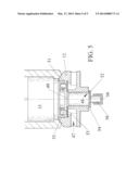
[0020] FIG. 5 is a partial cross section of the spherical joint of the piston.
DETAILED DESCRIPTION OF THE PREFERRED EMBODIMENTS
[0021] The new pump (FIG. 1) consists of housing 1, a centrally located camshaft 2 and cylinder assemblies 3 located in radial direction between camshaft and housing.
[0022] Rotation of the camshaft, results in a reciprocating movement of the piston within the cylinder, creating a pumping action.
[0023] The cylindrical face 4 (FIG. 2) of piston 5 is in sliding contact with the cylindrical face 6 of cam 7 of the camshaft.
[0024] The spherical face 8 of the cylinder 9 at the opposite end of the cylinder bore 10 is in sliding contact with the spherical face 11 of cylinder joint 12.
[0025] The pivotal movement of cylinder 9 allows for a self-adjustment of cylindrical face 4 of the piston to the cylindrical face 6 of the cam shaft, significantly reducing leakage, friction, and wear.
Piston Force Compensation
[0026] The cam 7(FIG. 2) advances the piston from Bottom End Position (BEP) 13 to Top End Position (TEP) 14, and piston chamber 15 receives fluid through cylinder joint 12 during the first half of the revolution. Fluid is pumped during the second half of the revolution when advancing the piston from TEP to BEP. The fluid pressure creates the piston force 16 applied to the camshaft 2, supported by the camshaft bearings 17 and 18 (FIG. 1).
[0027] The new pump configuration consists of pistons in four planes 19, 21, 26 and 27. The cams of the four planes are symmetrically arranged around center plane 26 of the camshaft in axial direction. The outer cams 7 and 27 are concentric to each other and oppose the inner cams 28 and 29 by 180 degrees in rotational direction of centerline 20. The piston forces 16 in planes 19 and 21 spaced to each other in axial direction of the centerline with cams opposing the piston forces in planes 21 and 24 by 180 degrees, balancing the sum of all piston forces in radial and axial direction. The compensation of all piston forces 16 eliminates the effects of piston forces at the camshaft bearings 17 and 18, significantly reducing leakage, friction, and wear and increasing longevity.
[0028] The complete balancing of the piston forces is also achieved by a configuration with pistons in three planes where the pistons in center plane 26 having twice the piston force than the pistons at the outer cams.
Integration of Rotor Bearings
[0029] Pump 30 (FIG. 3) and rotor 31 of the turbine have a common shaft, the camshaft 2 centrally attached to rotor hub 32 and rotatable mounted in the bearings 17 and 18, carrying the piston forces 16 and the weight 33 and wind forces 34 of the rotor, eliminating separate shaft, bearings and a clutch to transmit the power of the turbine, significantly reducing frictional losses, weight, space requirements, maintenance, and costs.
[0030] The weight 33 at the center of gravity of the rotor is preferably located near at or between bearings 17 and 18 to minimize bearing loads and deflection of the camshaft.
Self-aligning Shaft Bearings
[0031] The bearings 17 and 18 (FIG. 3) are pivotally mounted in pump housing 1 or structure of the nacelle to compensate for manufacturing tolerances, misalignments and deflection.
[0032] Hydrostatic bearings, compensating more than 90% of the bearing load through hydraulic pressure fields, are applied to support camshaft 2 of the pump allowing for low frictional losses, infinite life, and low maintenance. Pressurized fluid is applied to a defined pocket area 35 between camshaft and bearings, creating a hydraulic force reducing or eliminating the mechanical contact force between the parts. When overcompensated, the shaft is lifted and the flow of fluid reduces the fluid pressure supplied and therefore the hydraulic force balancing the bearing force.
[0033] The weight 33 of the rotor and the remaining sum of piston forces 16 are supported by the mechanical 36 and hydraulic forces 37 of bearings 17 and 18. The size of pocket area 35 and pressure of the fluid balance or nearly balance the sum of piston forces and the weight of the shaft. The mechanical contact force 36, forces not carried by the hydraulic pressure fields 37 align the bearings to the camshaft.
[0034] To reduce the mechanical forces needed for the alignment of the bearings, the forces between bearing and housing are supported by a hydrostatic pressure field to reduce the mechanical contact force. The outer spherical faces 38 of the bearings match the shape of housing 1, providing the sealed pocket 39 for a hydrostatic bearing. Pressurized fluid is applied to pockets 35 and 39 for increasing the hydraulic force 37 and reducing mechanical contact force 36 to minimize friction and wear.
[0035] The pressurized fluid can be supplied from one or more sources with the same or a different pressure than the pressure of the fluid transmitting the power of the wind turbine. Alternatively, a spherical element of small dimensions, as shown in FIG. 4 is utilized to support of the bearing house, requiring smaller forces for aligning bearing and shaft to each other.
[0036] The axial bearing 40 (FIG. 4) has a spherical face 41 matching the shape of its support structure at housing 1 providing a hydraulically sealed pocket 42 for a hydrostatic bearing, supporting the axial force 34 of the rotor. The axial bearing has face 43 with pocket 44 opposite the spherical face 41 in contact with axial face 45 of the camshaft. Pressurized fluid is applied to pockets 42 and 44 for increasing the hydraulic force 46 and reducing the mechanical contact force between axial bearing and camshaft to minimize friction and wear.
Co-axial Cylinder Joint Valves
[0037] Ingress 47 (FIG. 5) and egress 48 of the fluid to piston chamber 15 is controlled by check valves 49 and 50, co-axially arranged and integrated into cylinder joint body 12, reducing the clearance volume for lowering the compression losses, the flow resistance for improved efficiency and simplifying the hydraulic circuit of housing 1. Moving the piston 5 towards Bottom End Position (BEP) 13 reduces the pressure in piston chamber 15 and the higher pressure at ingress port 47 overcoming the force of spring 55 lifts valve plate 51 and fluid flows into the piston chamber. When reaching BEP, no fluid is flowing and the spring closes the valve. When moving the piston towards Top End Position (TEP) 14 the pressure in the piston chamber increases and opens valve 50 by overcoming the force of spring 56.
[0038] Valve plates 51 and 52, are preferably used for opening and closing ports 53 and 54 for ingress and egress, providing low weight for high frequency operation, small space requirements, and improved longevity and cost. Springs 55 and 56 hold the valve plates in their closed position. The co-axial arrangement of the valves 49 and 50 is also beneficial in assemblies other than the joint body.
User Contributions:
Comment about this patent or add new information about this topic:
Images included with this patent application:
 |  |
 |  |
 |
| Similar patent applications: | |
| Date | Title |
|---|---|
| 2009-12-24 | Hydraulic intensifiers |
| 2010-08-12 | Hydraulic apparatus |
| 2013-01-03 | Micropump and driving method thereof |
| 2009-12-24 | Hydraulic pump |
| 2013-08-29 | Hydraulic pump |
| New patent applications in this class: | |
| Date | Title |
|---|---|
| 2017-08-17 | Volumetric pump with bleed mechanism |
| 2016-04-28 | High-pressure pump |
| 2016-04-14 | Air compressor |
| 2015-10-22 | Pump and gas booster using same |
| 2015-10-22 | Pressure relief valve for single plunger fuel pump |
| New patent applications from these inventors: | |
| Date | Title |
|---|---|
| 2014-07-24 | Reciprocating exhaust mechanism for energy recuperation and gas recirculation |
| 2014-03-27 | Vtol aircraft with propeller tiltable around two axes and a retractable rotor |
| Top Inventors for class "Pumps" | |
| Rank | Inventor's name |
|---|---|
| 1 | Masaki Ota |
| 2 | Ken Suitou |
| 3 | Alex Horng |
| 4 | Yusuke Yamazaki |
| 5 | Lars Hoffmann Berthelsen |