Patent application title: PUMP AND GAS BOOSTER USING SAME
Inventors:
Suk Shin In
Suk Shin In (Gwangju, JP)
IPC8 Class: AF04B5310FI
USPC Class:
417559
Class name: Pumps expansible chamber type having pumping chamber pressure responsive distributor
Publication date: 2015-10-22
Patent application number: 20150300351
Abstract:
Provided is a gas buster including: a pump including a cylinder part, a
pump housing configured to be in communication with the cylinder part and
having a first intake part and a first exhaust part, a piston
reciprocably installed at the cylinder part to suck and exhaust water, a
first check valve installed at the first intake part to be opened when
the piston is moved backward and to be closed when the piston is moved
forward, a second check valve installed at the first exhaust part to be
opened when the piston is moved forward and to be closed when the piston
is moved backward, and a gas supply part installed at the pump housing,
and configured to supply a gas into an auxiliary cylinder part and thus
to add the gas to the water pumped by the cylinder and the piston; a
storage tank which is connected with the first exhaust part of the pump
and in which the gas added to the fluid is separated and compressed; and
a return pipe configured to connect the storage tank with the first
intake part.Claims:
1. A pump comprising: a cylinder part; a pump housing configured to be in
communication with the cylinder part and having a first intake part and a
first exhaust part; a piston reciprocably installed at the cylinder part
to suck and exhaust an incompressible fluid; a first check valve
installed at the first intake part to be opened when the piston is moved
backward and to be closed when the piston is moved forward; a second
check valve installed at the first exhaust part to be opened when the
piston is moved forward and to be closed when the piston is moved
backward; an auxiliary cylinder part installed at the pump housing to be
in communication with the cylinder part; and a gas supply part configured
to supply a gas to the auxiliary cylinder part so as to add the gas to
the incompressible fluid pumped by the piston.
2. A gas buster comprising: a pump having a pump housing in which a cylinder part is provided to add a gas to be compressed to an incompressible fluid in a compression driving part and then to pump them; a storage tank connected with a first exhaust part of the pump through a supply pipe, and having an internal space in which the gas added to the fluid is separated, and also configured to compress the separated gas; a return pipe configured to connect the storage tank with a first intake part in communication with the cylinder part of the pump; and a gas supply part configured to supply the gas to be compressed into the cylinder part for pumping a compressed fluid.
3. A gas buster comprising: a pump comprising a cylinder part, a pump housing configured to be in communication with the cylinder part and having a first intake part and a first exhaust part, a piston reciprocably installed at the cylinder part to suck and exhaust water, a first check valve installed at the first intake part to be opened when the piston is moved backward and to be closed when the piston is moved forward, a second check valve installed at the first exhaust part to be opened when the piston is moved forward and to be closed when the piston is moved backward, and a gas supply part installed at the pump housing, and configured to supply a gas into an auxiliary cylinder part and thus to add the gas to the water pumped by the cylinder and the piston; a storage tank which is connected with the first exhaust part of the pump and in which the gas added to the fluid is separated and compressed; and a return pipe configured to connect the storage tank with the first intake part.
4. The gas buster of claim 3, wherein the gas supply part comprises a supply hole connected through a gas supply pipe with a supply part installed at the pump housing to be in communication with the auxiliary cylinder part of the pump housing, and a third check valve installed at the supply hole to be opened when the fluid is sucked by the piston and to be closed when the piston is moved forward and the fluid is exhausted and thus to prevent the gas from flowing back.
5. The gas buster of claim 4, wherein the incompressible gas is a lubricating oil.
Description:
TECHNICAL FIELD
[0001] The present invention relates to a pump and a gas buster using the same, and more particularly, to a pump which is capable of adding a gas as a compressible fluid to a pumped incompressible fluid and then extruding the gas, and a gas buster using the same.
BACKGROUND ART
[0002] Generally, a pump for carrying a fluid or slurry is selected according to various factors such as a head pressure, a measuring accuracy, a temperature, a particle tolerance, a fluid viscosity, a price, stability and service fee.
[0003] A positive displacement pump includes a reciprocating pump as a lobe pump and a rotary pump. The reciprocating pump includes a mechanical/pneumatic piston pump and a mechanical/hydraulic diaphragm pump. The reciprocating pump has a structure in which one or more heads for transferring a fluid between a low pressure input side and a high pressure output side are provided, and a means for physically controlling an internal volume of a pumped fluid is installed at a pump head. A piston installed at a pump housing of the reciprocating pump is driven by a cam or a crank shaft and a connecting rod. The piston which reciprocates along a cylinder of the pump housing sucks the fluid from an inlet port, while increasing the internal volume of the cylinder, and discharges the fluid to an outlet port, while reducing the internal volume.
[0004] Most of the reciprocating pumps operate in only one direction. A flowing direction is controlled by a check valve, and the check valves isolate an inlet/outlet port pressure from the pump head during sucking and discharging processes. In general, the outlet port pressure is not controlled by the pump, but is controlled by a downstream side resistance of the working fluid due to the pump.
[0005] When the reciprocating pump is used in a high compressible fluid such as gas, it is called a compressor or a gas buster. A basic core element of the gas buster is a compression ratio. The compression ratio is a ratio of a maximum volume in which the pump head may be isolated between check valves at a peak of an intake stroke and a minimum volume which is reduced to an end of a delivery stroke.
[0006] In the pump, to increase a compression pressure of the compressible gas, it is recommended that the volume is as small as possible and the compression ratio is increased. When the pump is operated and a high temperature gas is remained in the pump, pump efficiency is lowered, and this is because the remaining fluid expands in the cylinder during the intake stroke, before a new fluid is introduced into the pump head. Due to such an action, it is difficult to compress the gas as the compressible fluid with a high pressure using the gas buster. To compress the gas with the high pressure, a multistage pump is used. However, the multistage pump has a relatively complicated structure.
DISCLOSURE
Technical Problem
[0007] The present invention is directed to providing a pump which is capable of adding a gas as a compressible fluid to a pumped incompressible fluid and then extruding the gas, and a gas buster using the same.
[0008] Also, the present invention is directed to providing a pump which is capable of separating the gas added to the incompressible fluid, and compressing the gas, and thus increasing compression efficiency of the gas, and also enhancing lubricity of a piston and a cylinder as driving parts of the pump, and a gas buster using the same.
Technical Solution
[0009] One aspect of the present invention provides a pump including a cylinder part; a pump housing configured to be in communication with the cylinder part and having a first intake part and a first exhaust part; a piston reciprocably installed at the cylinder part to suck and exhaust an incompressible fluid; a first check valve installed at the first intake part to be opened when the piston is moved backward and to be closed when the piston is moved forward; a second check valve installed at the first exhaust part to be opened when the piston is moved forward and to be closed when the piston is moved backward; an auxiliary cylinder part installed at the pump housing to be in communication with the cylinder part; and a gas supply part configured to supply a gas to the auxiliary cylinder part so as to add the gas to the incompressible fluid pumped by the piston.
[0010] Another aspect of the present invention provides a gas buster including a pump having a pump housing in which a cylinder part is provided to add a gas to be compressed to an incompressible fluid in a compression driving part and then to pump them; a storage tank connected with a first exhaust part of the pump through a supply pipe, and having an internal space in which the gas added to the fluid is separated, and also configured to compress the separated gas; a return pipe configured to connect the storage tank with a first intake part in communication with the cylinder part of the pump; and a gas supply part configured to supply the gas to be compressed into the cylinder part for pumping a compressed fluid.
[0011] Still another aspect of the present invention provides a gas buster including a pump including a cylinder part, a pump housing configured to be in communication with the cylinder part and having a first intake part and a first exhaust part, a piston reciprocably installed at the cylinder part to suck and exhaust water, a first check valve installed at the first intake part to be opened when the piston is moved backward and to be closed when the piston is moved forward, a second check valve installed at the first exhaust part to be opened when the piston is moved forward and to be closed when the piston is moved backward, and a gas supply part installed at the pump housing, and configured to supply a gas into an auxiliary cylinder part and thus to add the gas to the water pumped by the cylinder and the piston; a storage tank which is connected with the first exhaust part of the pump and in which the gas added to the fluid is separated and compressed; and a return pipe configured to connect the storage tank with the first intake part.
[0012] The gas supply part may include a supply hole connected through a gas supply pipe with a supply part installed at the pump housing to be in communication with the auxiliary cylinder part of the pump housing, and a third check valve installed at the supply hole to be opened when the fluid is sucked by the piston and to be closed when the piston is moved forward and the fluid is exhausted and thus to prevent the gas from flowing back.
Advantageous Effects
[0013] The pump and the gas buster using the same according to the present invention can add the gas to the pumped incompressible fluid, and then can compress the gas, and also can separate the gas in the storage tank, thereby enhancing the compression efficiency of the gas. Also the gas buster using the pump of the present invention can satisfy a user's requirement for the compression pressure of the gas.
DESCRIPTION OF DRAWINGS
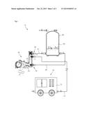
[0014] FIG. 1 is a view illustrating a gas buster according to the present invention.
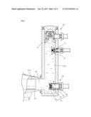
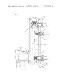
[0015] FIG. 2 extracts and illustrates a cylinder part and an auxiliary cylinder part of a pump, and is a cross-sectional view illustrating a state in which an incompressible fluid is sucked into a cylinder through a first inlet port to compress the incompressible fluid.
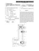
[0016] FIG. 3 extracts and illustrates the cylinder part and the auxiliary cylinder part of the pump, and is a cross-sectional view illustrating a state in which the incompressible fluid added to a gas is compressed through a first outlet port to compress the incompressible fluid.
MODES OF THE INVENTION
[0017] A pump and a gas buster using the same according to the present invention add a gas to a fluid, and then compress the gas, and one embodiment thereof is illustrated in FIGS. 1 to 3.
[0018] Referring to the drawings, a gas buster 10 according to the present invention includes a pump 20 having a pump housing 23 in which a cylinder part 22 is provided to add a gas to be compressed to an incompressible fluid in a compression driving part 21 and then to pump them, a storage tank 60 connected between a first exhaust part 30 of the pump 20 and a supply pipe 61, and having an internal space in which the gas added to the fluid is separated, and also configured to compress the separated gas, and a gas supply part 70 having a return pipe 62 for connecting the storage tank 60 with a first intake part 40 in communication with the cylinder part 22 of the pump 20, and configured to supply the gas to be compressed into the cylinder part 22 for pumping a compressed fluid.
[0019] The compression driving part 21 of the pump 20 for compressing an incompressible fluid added to the compressible gas includes a piston 21a which is reciprocably installed in the cylinder part 22 provided at the pump housing 23 to suck the incompressible fluid through the first intake part 40 and then to exhaust the incompressible fluid through the first exhaust part 30, and a piston driving part 21b which moves the piston 21a forward and backward along the cylinder part 22. A plurality of pistons and cylinder parts may be installed at the pump housing 23. The piston driving part 21b includes a crank shaft which is driven by an engine or a motor, and a connecting rod which connects the crank shaft and the piston so as to convert a rotating force of the crank shaft into a linear reciprocating motion.
[0020] The compression driving part is not limited to the above-described embodiment, and may include a vane, a gear and an impeller which are installed in the cylinder part, and a driving part which rotates the vane, the gear and the impeller.
[0021] A first check valve 31 which is opened by the compression driving part 21 when the fluid is sucked, and closed when the fluid is compressed is installed at the first intake part 30 installed to be in communication with the cylinder part 22, and a second check valve 41 which is opened by the compression driving part 21 when the fluid is compressed, and closed when the fluid is sucked is installed at the first exhaust part 40. The check valve does not have to be installed at the first intake part 30 and the first exhaust part 40, which are in communication with the cylinder part, according to kinds and characteristics of the compression driving part.
[0022] Meanwhile, the pump housing 23 further includes an auxiliary cylinder part 22a to add the gas to the incompressible fluid pumped by the cylinder part 22 and the piston 21a. The auxiliary cylinder part 22a may be integrally formed with the pump housing 23. Alternatively, an auxiliary pump housing having the auxiliary cylinder part may be manufactured and then installed at the pump housing 23 so that the cylinder part 21 is in communication with the auxiliary cylinder part 21a (22a). Here, it is preferable that the auxiliary cylinder part 22a is in communication with the cylinder part 22, and extends in an upper direction of the cylinder part 22, and the first intake part 30 is installed at the lower side pump housing 23 of the auxiliary cylinder part 22a, and the first exhaust part 40 is installed at the upper side pump housing 23 of the auxiliary cylinder part 22a. This is to prevent the gas supplied through the gas supply part 70 from being introduced into the cylinder part 22 for compressing the incompressible fluid. Preferably, a volume of the auxiliary cylinder part 22a is formed larger than or the same as a volume in which water is pumped by the cylinder part 22 and the piston 21a.
[0023] Meanwhile, the gas supply part 70 serves to supply the gas to be compressed into the cylinder part 22 or the auxiliary cylinder part 22a, and has a gas supply hole 71 formed at the pump housing 23, and the gas supply hole is connected with a gas compressor 72 for supplying the gas to be compressed, or a gas tank and a gas supply pipe 73. A third check valve 75 which prevents the incompressible fluid from flowing back through the gas supply part, when the piston 21a of the compression driving part 21 is moved forward, is installed at the gas supply hole 71. A supply pressure of the gas supplied through the gas supply pipe 73 is not required to be relatively higher than a pressure which compresses the incompressible fluid. The gas supply pipe may further include a pressing pump which is interlocked with the piston of the compression driving part, and supplies the gas to be compressed.
[0024] An incompressible fluid 100 which is circulated through the return pipe 62, the cylinder part 22 and the supply pipe 61 is stored in the storage tank 60. The incompressible fluid 100 may be a lubricating oil or water which reduces friction between the piston and the cylinder, but is not limited thereto.
[0025] As illustrated in FIG. 2, the first check valve 31 installed at the first intake part 30 includes a valve housing 33 having a valve seat part 32 installed at the first intake part 30 of the pump housing, a valve member 34 which is slidably installed at the valve housing 33 to control supplying of the water in contact with the valve seat part 32, and a spring 35 which is installed between the valve member 34 and the valve housing 33 to elastically bias the valve member 34 in a closing direction when the piston 21a moved along the cylinder part 22 is moved forward.
[0026] The second and third check valves 41 and 75 substantially have similar structure to the first check valve 31. The closing direction of the valve member in the second and third check valves 41 and 75 may be changed according to an operation state of the piston 21a which is reciprocated along the cylinder part 22.
[0027] The storage tank 60 has an internal space in which the incompressible fluid 100 and the compressed gas are stored simultaneously. The compressed gas added to the incompressible fluid 100 is separated in the internal space of the storage tank 60 due to a difference in a specific gravity. The incompressible fluid is stored at a lower side of the internal space of the storage tank 60, and the compressible gas is stored at an upper side thereof. The storage tank 60 may further include a tank which separately stores the compressible gas.
[0028] An operation of the gas buster having the above-described structure of the present invention will be described.
[0029] To compress the gas using the gas buster, the pump 20 is driven to pump the incompressible fluid 100 in the storage tank 60. Like this, the incompressible fluid 100 is circulated from the storage tank 60 to the return pipe 62, the first intake part 30, the cylinder part 22, the first exhaust part 40, the supply pipe 61 and the storage tank 60.
[0030] In this process, the gas to be compressed is supplied to the cylinder part 22 using the gas supply part 70. The supplied gas is added to the incompressible fluid 100 which is compressed in the cylinder part 22 or the auxiliary cylinder part 22a, and then pumped to the storage tank 60 through the first exhaust part 40 and the supply pipe 61.
[0031] In the case in which the incompressible fluid 100 is sucked by the piston 21a of the compression driving part 21, which is reciprocated in the cylinder, even when the compressible gas is supplied, the gas is moved toward the first exhaust part 40, and thus the compressible fluid is not introduced into the cylinder part 22 as a substantial compressing area in which the piston is reciprocated.
[0032] When the lubricating oil is used as the incompressible fluid 100, a lubrication action between the cylinder part and the piston may be activated and also may prevent the compressible fluid from leaking through the compression driving part.
[0033] The incompressible fluid 100 added to the gas as the compressible fluid is supplied to the storage tank 60 through an exhaust port, and the compressible gas and the incompressible fluid are separated in the internal space of the storage tank 60 by the difference in the specific gravity. The separated gas is located at the upper side of the storage tank, and the incompressible fluid is located at the lower side thereof and then circulated as described above.
[0034] As described above, the gas buster according to the present invention can add the compressible gas to the incompressible fluid, can compress them, and then can separate them using the difference in the specific gravity, thereby enhancing compression efficiency of the gas as the compressible fluid.
[0035] Although a few embodiments of the present invention have been shown and described, it would be appreciated by those skilled in the art that changes may be made in these embodiments without departing from the principles and spirit of the invention, the scope of which is defined in the claims and their equivalents.
User Contributions:
Comment about this patent or add new information about this topic:
Images included with this patent application:
 |  |
 |  |
| Similar patent applications: | |
| Date | Title |
|---|---|
| 2016-01-28 | Electro-osmotic pump using reversible electrode reaction and fluid pumping system using same |
| 2016-01-07 | Oil pump and power transmitting device equipped with the same |
| 2015-12-24 | Exhaust-gas turbocharger and method for producing a flow housing of an exhaust-gas turbocharger |
| 2016-01-07 | Pump device and method for controlling the same |
| 2015-12-17 | Valve device and high-pressure pump using the same |
| New patent applications in this class: | |
| Date | Title |
|---|---|
| 2017-08-17 | Volumetric pump with bleed mechanism |
| 2016-04-28 | High-pressure pump |
| 2016-04-14 | Air compressor |
| 2015-10-22 | Pressure relief valve for single plunger fuel pump |
| 2015-02-12 | Automatic valve with a spring holder ring |
| Top Inventors for class "Pumps" | |
| Rank | Inventor's name |
|---|---|
| 1 | Masaki Ota |
| 2 | Ken Suitou |
| 3 | Alex Horng |
| 4 | Yusuke Yamazaki |
| 5 | Lars Hoffmann Berthelsen |