Patent application title: GROUND COVER MATS WITH CROSS BEAM STRAPS
Inventors:
Robert Fournier (Nisku, CA)
Assignees:
MAXXIMAT INC.
IPC8 Class: AE01C908FI
USPC Class:
404 35
Class name: Pavement modules or blocks (preformed) portable mat type
Publication date: 2013-11-21
Patent application number: 20130309008
Abstract:
Reinforced ground cover mats are used to facilitate the passage of heavy
equipment and vehicles on wet or disturbed ground. The ground cover mats
are comprised of boards contained within a peripheral metal frame. A
plurality of cross beam straps are disposed in transverse groove cut into
the planar surfaces of the mat boards, and the ends are tucked within the
frame members and lap welded.Claims:
1. A ground cover mat comprising: (a) a quadrilateral frame comprised of:
(i) two substantially parallel opposing end members; and (ii) two
substantially parallel outside longitudinal members, each having an inner
channel; (b) two opposing major surfaces formed from a plurality of
elongate boards retained within the frame, wherein at least one major
surface defines a transverse groove substantially parallel to the end
members; and (c) at least one cross beam strap disposed within the
transverse groove, wherein each end of the strap is disposed within a
longitudinal member inner channel, and wherein the strap is substantially
flush with a major surface of the mat.
2. The mat of claim 1 further comprising a third longitudinal member comprising an I-beam mid rail substantially bisecting the mat parallel to the longitudinal members, and attached to the end members.
3. The mat of claim 1 comprising at least two cross beam straps, one on each opposing major surface, and aligned with each other.
4. The mat of claim 2 comprising at least four cross beam straps, wherein at least two cross beam straps are on each opposing major surface, and aligned with each other.
5. The mat of claim 3 wherein opposing cross beam straps are affixed to each by means of a pin passing through the mat and attached to each strap.
6. The mat of claim 1 wherein the ends of the at least one cross beam strap are lap welded to the longitudinal members.
7. The mat of claim 1 comprising a plurality of cross beam straps spaced within the frame in an equidistant manner.
Description:
CROSS REFERENCE TO RELATED APPLICATION
[0001] This application claims the priority of Canadian Patent Application 2,776,732 filed on May 15, 2012 entitled "Ground Cover Mats With Cross Beam Straps", the contents of which are incorporated herein by reference.
FIELD OF THE INVENTION
[0002] The present invention relates to improved ground cover mats.
BACKGROUND OF THE INVENTION
[0003] In the oil and gas industry, it is sometimes necessary to provide ground cover mats with sufficient strength to support heavy equipment and transport trucks over wet or disturbed ground.
[0004] Several prior art ground cover mats exist; however, they sometimes lack sufficient reinforcement to withstand the pressure of heavy equipment and transport trucks, and are expensive to produce. What is needed is an improved ground cover mat which is simple and relatively inexpensive and has sufficient strength and durability to support heavy equipment.
[0005] Further, ground cover mats tend to be extremely heavy and lengthy, making the mats difficult to store, lift, transport, assemble or disassemble. Since a series of mats are generally required to construct a temporary road, an improved ground cover mat which is easy to handle is desirable.
[0006] There have been attempts in the prior art to solve such problems. For example, U.S. Pat. No. 4,462,712 issued Jul. 31, 1984 to Penland, Sr. describes an interlocking mat assembly comprising assemblies of two-ply laminated mats which interlock and are secured together by nailing a top layer of planks over the interlocked mats. However, this mat assembly is particularly labor intensive.
[0007] Canadian Patent No. 1,285,166 issued Jun. 25, 1991 to Pouyer describes a temporary road which includes a plurality of sets, each defined by upper and lower matrices with the upper matrices comprising boards and the lower matrices comprising cross-support members for supporting the boards. The road is constructed by interlocking series of sets in a superimposed assembly, necessitating significant redundancy of effort in assembly and disassembly.
[0008] U.S. Pat. No. 6,695,527 issued Feb. 24, 2004 to Seaux et al. describes interlocking mats constructed of two mirror half pieces which are joined together to form a complete single mat containing an internal cellular structure. Traction promoting elements in the form of raised strips extending outward from the planar surfaces of the mats and aligned with the internal cell forming walls are provided to improve traction and to absorb heavy loading from vehicles and equipment. However, Seaux et al. indicates that when a large number of the raised strips are not specifically positioned in such a manner, the relatively thin outer skin defining the roughly planar surfaces of the mats can become easily deformed by such direct loading.
[0009] U.S. Pat. Nos. 4,600,336 and 5,087,149 issued Jul. 15, 1986 and Feb. 11, 1992 respectively, to Waller describe mat systems having individual mats with alternating offset extensions and recesses along the edges. These systems are disadvantageous in that the offset extensions are comprised of individual planks which may be subject to warping or splintering when exposed to heavy loads. Further, the offset extensions need to be nailed in place to be secured within the recess of an adjacent mat. An extra plank is secured over the exposed nailed joints of adjacent mats to interlock the mat assemblies together as a roadway, which significantly increases material and labor requirements.
[0010] Canadian Patent No. 2,348,328 issued Oct. 22, 2002 to Stasiewich et al describes a road mat including, at both of its ends, couplings having retaining lips which engage complimentary retaining lips of adjacent mats to prevent separation when weight applied by a vehicle to one road mat is transferred to an adjacent road mat. Canadian Patent No. 2,364,968 issued Jun. 22, 2004 to Stasiewich et al describes a road mat having end and side interlocks to secure adjacent mats. However, there is no provision in either patent of details regarding attachment of the retaining lips to the mat ends, or the use of any reinforcing structural support.
[0011] The present invention addresses the above shortcomings of the prior art, meeting the need for an improved ground cover mat which has sufficient strength to support heavy equipment, provides easy handling, and is simple and relatively inexpensive.
SUMMARY OF THE INVENTION
[0012] The present invention is directed to ground cover mats. In one aspect of the invention, the invention comprises a ground cover mat comprising:
[0013] (a) a quadrilateral frame comprised of:
[0014] (i) two substantially parallel opposing end members; and
[0015] (ii) two substantially parallel outside longitudinal members, each having an inner channel;
[0016] (b) two opposing major surfaces formed from a plurality of elongate boards retained within the frame, wherein at least one major surface defines a transverse groove substantially parallel to the end members; and
[0017] (c) at least one cross beam strap disposed within the transverse groove, wherein each end of the strap is disposed within a longitudinal member inner channel, and wherein the strap is substantially flush with a major surface of the mat.
[0018] In one embodiment, the mat comprises a third longitudinal member comprising an I-beam mid rail which is parallel to the two outside longitudinal members and attaches to the end members, substantially bisecting the mat. Where a mid rail is used, the cross beam straps attach to the outside longitudinal member and the mid rail.
[0019] In one embodiment, cross strap beams are provided on each opposing major surface. The cross strap beams may be aligned with each other and a pin used to attach the two straps to each other.
BRIEF DESCRIPTION OF THE DRAWINGS
[0020] The invention will now be described by way of an exemplary embodiment with reference to the accompanying simplified, diagrammatic, not-to-scale drawings.
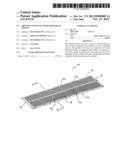
[0021] FIG. 1 is a diagrammatic representation of a mat of one embodiment of the present invention.
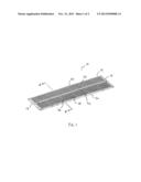
[0022] FIG. 2 is a cross-sectional view of a mat, along line II-II in FIG. 1.
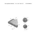
[0023] FIGS. 3A and 3B are detailed views of portions of FIG. 2.
DETAILED DESCRIPTION OF THE INVENTION
[0024] The present invention provides for reinforced ground cover mats. When describing the present invention, all terms not defined herein have their common art-recognized meanings. To the extent that the following description is of a specific embodiment or a particular use of the invention, it is intended to be illustrative only, and not limiting of the claimed invention. The following description is intended to cover all alternatives, modifications and equivalents that are included in the spirit and scope of the invention, as defined in the appended claims.
[0025] The invention will now be described having regard to the accompanying Figures. The mat (10) is comprised of a quadrilateral frame (12), and planar surfaces formed from a plurality of elongate boards (14). A suitable mat is described in Applicant's co-owned U.S. Pat. No. 7,934,885, the entire contents of which are incorporated herein by reference, where permitted.
[0026] The quadrilateral frame (12) comprises two substantially parallel opposing end members (18) and two substantially parallel outside longitudinal members (20). Each end member (18) has an inner slot (24) facing the opposing end member (18). Each longitudinal member (20) has a slot (not shown) facing the opposing longitudinal member (20).
[0027] The elongate boards (14) are retained within the frame (12). The mat (14) forms two opposing major surfaces (28). The mat boards (14) insert into, and are retained by the inner slots (24) of the end members (18).
[0028] In one embodiment, each board (14) has a substantially rectangular cross-section and is disposed such that the vertical dimension of the board (14) is larger than the horizontal dimension, thus increasing the bending strength of the mat (10). The boards may be glued together and staggered to increase the strength of the mat. The boards (14) may be single 2×4 or 2×6 boards or may be constructed using wood layers bonded to composite material layers.
[0029] In one embodiment, the board comprises at least one wood layer bonded to at least one composite material layer. As used herein, the term "composite" refers to any engineered material made from two or more constituent materials with significantly different physical or chemical properties and which remain separate and distinct on a macroscopic level within the finished structure. In one embodiment, the composite material layers may comprise fiberglass; however, such other materials as are commonly used in the art may also be employed for the boards (14).
[0030] The frame (12) is constructed from any suitable material such as steel. In one embodiment, the frame (12) may comprises a third longitudinal member comprising a mid rail (32) which is connected at each end to the midpoint of each end member (18) in an orientation that is substantially parallel to each longitudinal member (20). In one embodiment, the mid rail (32) is an I-beam, thereby having slots (34) facing the longitudinal members (20). The boards (14) insert into, and are retained by the slots (34) on the mid rail (32).
[0031] A plurality of cross beam straps (36) are arranged in an orientation that is substantially parallel to the opposing end members (18). Each Cross-beam strap (36) comprises a flat metal bar, and is connected at one end to the mid rail (32) and at the other end to a longitudinal member (20). In the prior art, cross beam straps are used but are butt-welded to the longitudinal members and the mid rail, such that it is disposed on top of the boards (14) and flush with the longitudinal members and mid rail. In the present invention, the applicant has found that by modifying the installation of the cross beam strap, significantly better results may be obtained.
[0032] As shown in FIG. 2, a transverse groove is cut into the boards (14) having a depth approximately equal to the thickness of the cross beam strap (36). The strap (36) is lengthened slightly such that the ends overlap and slide under the longitudinal member channel on one side, and within the mid rail I-beam channel on the other side. The strap is then lap welded into place, as shown in FIGS. 3A and 3B. In an embodiment where no mid rail is in place, the cross beam strap will extend across the entire mat and be affixed to both longitudinal members. Accordingly, the strength of the weld attaching the cross beam strap is much stronger, and even if the weld breaks, the strap is still held in place within the transverse groove, and by the ends which are tucked under the longitudinal members and the mid rail.
[0033] In one embodiment, cross beam straps (36) are aligned on either side of the mat, and held together by a pin (38) which is welded in place.
[0034] The number and spacing of the cross-beam straps may vary according to the size and construction of the mat. As shown in FIG. 1, an exemplary mat that is about 40 feet long and which is bisected by a mid rail, has 10 cross beam straps on each side, 20 in total, spaced in an equidistant manner between the two end members (18).
User Contributions:
Comment about this patent or add new information about this topic:
| People who visited this patent also read: | |
| Patent application number | Title |
|---|---|
| 20180077969 | METHOD FOR ASSEMBLING A CARTRIDGE FOR A SMOKING ARTICLE |
| 20180077968 | ATOMIZER HEAD, ATOMIZER AND ELECTRONIC CIGARETTE CONTAINING THE ATOMIZER |
| 20180077967 | LEAK-RESISTANT VAPORIZER DEVICE |
| 20180077966 | SMOKING ARTICLE WITH COMBUSTIBLE HEAT SOURCE GRIPPING MEANS |
| 20180077965 | AEROSOL GENERATOR |
Images included with this patent application:
 |  |
 |
| Similar patent applications: | |
| Date | Title |
|---|---|
| 2014-02-20 | Road barrier energy absorbing systems and methods for making and using the same |
| 2011-04-21 | Rebound control material |
| 2009-08-20 | Zero velocity bead dispenser |
| 2010-04-29 | Double-deck covered roadway |
| 2014-02-06 | Integrated frame and cover system |
| New patent applications in this class: | |
| Date | Title |
|---|---|
| 2016-06-23 | Environmentally resistant encapsulated mat construction |
| 2016-06-23 | Mat construction with environmentally resistant core |
| 2016-05-26 | Sealing panel device |
| 2016-04-28 | Rig mat with replaceable deck inserts |
| 2016-04-28 | Modular rig mat system |
| New patent applications from these inventors: | |
| Date | Title |
|---|---|
| 2014-07-10 | Ground cover mats with rectangular ends |
| Top Inventors for class "Road structure, process, or apparatus" | |
| Rank | Inventor's name |
|---|---|
| 1 | Günter Hähn |
| 2 | Martin Buschmann |
| 3 | Cyrus Barimani |
| 4 | Ralf Weiser |
| 5 | Ronald D. Shaw |