Patent application title: CLOUD SERVICES SYSTEM
Inventors:
Pietro Caminiti (Rome, IT)
Paolo Trevisan (Rome, IT)
Alessandro Duminuco (Vibonati Salerno, IT)
Simone Tiberia (Rome, IT)
Valerio Romano (Rome, IT)
Assignees:
ACCENTURE GLOBAL SERVICES LIMITED
IPC8 Class: AH04L1226FI
USPC Class:
709224
Class name: Electrical computers and digital processing systems: multicomputer data transferring computer network managing computer network monitoring
Publication date: 2013-09-12
Patent application number: 20130238788
Abstract:
A cloud services system includes an access services layer, a cloud
service manager, and a service platform layer. The access services layer
provides front-end functionality for users and service providers to order
and manage cloud services, including software applications provided for
use by the users. The cloud manager exposes services provided by the
cloud services system to the users, and orchestrates delivery of the
services and provisioning of resources for the services. The service
platform layer activates virtual machines and virtual desktops to provide
the services.Claims:
1. A cloud services system comprises: data storage; and a processor to
execute an access services layer, a cloud service manager, and a service
platform layer, wherein the access services layer provides front-end
functionality for users and service providers to order and manage cloud
services, including software applications provided for use by the users,
the cloud manager exposes services provided by the cloud services system
to the users, and orchestrates delivery of the services and provisioning
of resources for the services, and the service platform layer activating
virtual machines and virtual desktops to provide the services.
2. The cloud services system of claim 1, wherein the access services layer comprises a commercial portal, a user dashboard and an administrator portal.
3. The cloud services system of claim 1, wherein the cloud service manager comprises a common services integration layer, a core and a service platform integration layer.
4. The cloud services system of claim 3, wherein the common services integration layer comprises a service bus interfacing the cloud services system with user applications and service provider applications and a data repository of the cloud services system.
5. The cloud services system of claim 4, wherein the data repository stores a service catalog listing services provided by the cloud services system, service order information including service order data, progress status and service composition, and service configuration information including service configurations and usage.
6. The cloud services system of claim 3, wherein the service platform integration layer comprises an internal service bus connecting components of the cloud service manager with the service platform layer.
7. The cloud services system of claim 1, wherein the service platform layer comprises a cloud stack and virtual desktop administrator activating virtual servers and virtual desktops to host software applications for the cloud services.
Description:
BACKGROUND
[0001] Cloud computing typically involves using remote computing resources on a pay-per-use basis, where the remote computing resources may be used alone or in conjunction with internal computing resources. For example, processing resources and storage resources of a cloud service provider, such as Amazon Web Services, Microsoft Azure, or Rackspace Cloud Servers, can be requested and used on-demand in a scalable fashion. Cloud computing can be used to provide applications and information to end user devices, such as laptops, personal computers, thin clients, mobile devices, etc. Cloud computing can be used for applications with varying or unpredictable demand like year-end financials or tax-return preparation. Additionally, computationally-intensive processing, such as Monte Carlo simulations or protein folding, can be performed using cloud computing resources.
[0002] Given the variation in applications, variations in demand, variations in hosting platforms, and variations in end user devices, it can be difficult for a service provider to set up and implement cloud computing services. A cloud service provider should have skills and resources to provision (e.g., to define, make ready for use, setup, etc.), use and manage computing resources and applications. However, in many instances, a service provider planning to set up cloud services for the first time may lack familiarity with the provisioning and management of resources for cloud services. Also, the service provider may have a limited budget for the provisioning. As a result, it can be difficult, time consuming and cost prohibitive for a service provider to set up and provide cloud services.
SUMMARY
[0003] According to an embodiment, a cloud services system includes an access services layer, a cloud service manager, and a service platform layer. The access services layer provides front-end functionality for users and service providers to order and manage cloud services, including software applications provided for use by the users. The cloud manager exposes services provided by the cloud services system to the users, and orchestrates delivery of the services and provisioning of resources for the services. The service platform layer interacts with infrastructure in order to activate virtual machines and virtual desktops to provide the services.
[0004] The cloud services system may be implemented on a computer platform including a data storage and a processor. Methods may be performed by the cloud services system to provide cloud services to users. The methods may be embodied as machine readable instructions stored on a non-transitory computer readable medium and executable by a processor.
BRIEF DESCRIPTION OF THE DRAWINGS
[0005] Embodiments are described in detail in the following description with reference to the following figures. The embodiments are illustrated by way of example and are not limited by the accompanying figures in which like reference numerals indicate similar elements.
[0006] FIG. 1 shows an architecture of a cloud services system;
[0007] FIGS. 2A-E show components of an access services layer of the cloud service system;
[0008] FIGS. 3A-C show components of a cloud service manager of the cloud service system;
[0009] FIGS. 4A-B show components of a service platform layer of the cloud services system;
[0010] FIG. 5 shows the cloud services system used by different types of users;
[0011] FIG. 6 shows a flow chart of a method for providing cloud services; and
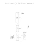
[0012] FIG. 7 shows a computer system that may be used as a platform for the cloud services system.
DETAILED DESCRIPTION
[0013] For simplicity and illustrative purposes, the principles of the embodiments are described by referring mainly to examples thereof. In the following description, numerous specific details are set forth in order to provide a thorough understanding of the embodiments. It is apparent however, to one of ordinary skill in the art, that the embodiments may be practiced without limitation to these specific details. In some instances, well known methods and structures have not been described in detail so as not to unnecessarily obscure the description of the embodiments. Furthermore, different embodiments are described below, and the embodiments may be used or performed together in different combinations.
[0014] According to an embodiment, a cloud services system is provided that may be implemented by a service provider or another entity. In one example, the cloud services system may be implemented by a telecommunications provider that may have the "pipes" for providing cloud services. "Pipes" includes the network infrastructure for providing the cloud services. The cloud services system may be implemented by entities other than a telecommunications provider.
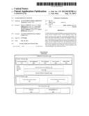
[0015] FIG. 1 illustrates a system architecture for a cloud services system 100, according to an embodiment. The architecture includes software components 110 and hardware components 150. The software components 110 may include an access services layer 120, a cloud service manager 130 and a service platform layer 140.
[0016] The access services layer 120 provides the front-end functionality for users and service providers. The access services layer 120 may include a commercial portal 121, a user dashboard 122 and an administrator portal 123. FIGS. 2A-C show aspects of the commercial portal 121, the user dashboard 122 and the administrator portal 123. The commercial portal 121, the user dashboard 122 and the administrator portal 123 may include a graphical user interface (GUI) that allows users to view and enter information. FIG. 2A shows some functions of the commercial portal 121. The commercial portal 121, for example, allows users of the cloud services system 100 to view service catalogs, perform self-ordering, receive quotations, request submissions and view invoice. The commercial portal 121 also provides order status tracking, an activated service view and functions for change request management. The commercial portal 121 may be used by large enterprises and small and medium enterprises or other types of users to access these functions provided by the cloud services system 100. The commercial portal 121 could be used for either internal (private) cloud or public cloud services.
[0017] FIG. 2B shows some functions of the user dashboard 122. The user dashboard 122, for example, allows the user to access service details, manage orders for cloud services, open and review ticket status, and review customer invoicing. The user dashboard 122 may be used by end user consumers, small businesses or other entities to perform these actions.
[0018] FIG. 2C shows some functions of the administrator portal 123. The administrator portal 123 may be used by the service provider implementing the cloud services system 100. The administrator portal 123, for example, allows an administrator or other user with appropriate access privileges to monitor and manage services, and perform trouble shooting. The administrator, via the administrator portal 123, may monitor and manage services, which may include monitoring orders and evaluating technical feasibility. The administrator portal 123 also allows the administrator to view and manage service configurations and usage.
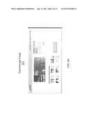
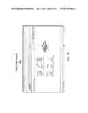
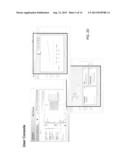
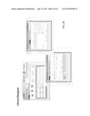
[0019] FIGS. 2D-G show examples of screenshots that may be generated via the commercial portal 121, the user dashboard 122, and/or the administrator portal 123. FIG. 2D shows a screen shot of service board and modifying resources for ordered services. FIG. 2D also shows screen shots of usage information for resources. FIG. 2E shows screenshots for identifying resources for designing the cloud services system and for designing cloud services to be administered by the cloud services system. The architecture design screenshot shows selecting servers, virtual servers and virtual desktops to provide cloud services. The service configuration screenshots show options for creating cloud services. Generally, the cloud design screenshots show that users can order and manage complex infrastructure architecture (virtual data center) or an administrator can create, validate and deliver custom services for an "ad hoc" initiative. The user console screenshots generally show that a user may manage its services through self-management interfaces with functionalities made available through the access services layer 120.
[0020] The cloud service manager 130 shown in FIG. 1 exposes the services provided by the cloud services system 100 to the users, and orchestrates service delivery, technical provisioning and other management functions. The cloud service manager 130 may include a common services integration layer 131, a core 132, and a service platform integration layer 133. The common services integration layer 131, the core 132, and the service platform integration layer 133 are further described with respect to FIGS. 3A-C.
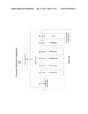
[0021] FIG. 3A shows the common services integration layer 131 integrating the functions of the cloud service manager 130 with the service provider and the user applications. For example, the common services integration layer 131 may comprise a service bus to provide services to external applications, which may include applications of the user and applications of the service provider. FIG. 3A shows the service bus connecting functions and an integrated repository of the cloud service manager 130 with user applications and service provider applications. For example, the functions of the cloud service manager 130 may include orchestration of services, access services, metering, and information technology (IT) service management integration. The service bus connects the functions of the cloud service manager 130 to an IT service management application of the service provider and a customer resource management and billing application of the service provider. The service bus also connects the functions with the enterprise applications of the user.
[0022] The integrated repository shown in FIG. 3A may include a central data repository containing a commercial and technical service catalog and hierarchy structure, service order information including service order data, progress status and service composition, and service configuration information including service configurations, usage and related open tickets for services.
[0023] The IT service management integration shown in FIG. 3A may include an application program interface integrating the IT service management application of the service provider with the cloud service manager 130. The IT service management application of the service provider may monitor hardware resources.
[0024] The metering function shown in FIG. 3A may include collection of resource usage data and applying charging rules based on the types of services being provided to the user. For example, the metering function may collect resource data information on virtual machine (VM) "active" status. The metering function may apply pay-per-use charging rules (e.g., flat fee per VM daily active status). The usage and charging data may be stored in the integrated repository.
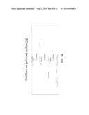
[0025] The core 132 orchestrates service delivery and management. FIG. 3B shows some of the functions performed by the core 132 to orchestrate service delivery and management. The core 132, for example, contains workflow logic for provisioning, metering and accounting, and ticket processing. The core 132 may perform automated tasks for providing resources on demand, usage data collection, data retrieval and storing into the integrated repository, customer and service configuration, and usage data communication to external applications for billing. The core 132 also facilitates tasks for assessing technical feasibility to provide services, design of services, and ticket management.
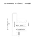
[0026] FIG. 3c shows the service platform integration layer 133 integrating the cloud service manager 130 with the service platform layer 140. The service platform integration layer 133, for example, operates as an internal service bus connecting components of the cloud service manager 130 with the service platform layer 140. For example, FIG. 3c shows the service platform integration layer 133 operating as an internal service bus connecting the cloud service manager 130 with a cloud stack for VM activation and with a virtual desktop administrator of the service platform layer 140.
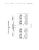
[0027] FIG. 1 shows the server platforms 140 including a virtual server/cloud stack 141 and virtual desktop manager 142. The cloud stack provides capabilities to activate infrastructure as a service, including VMs , operating systems, firewalls, software applications, and hypervisors. FIG. 4A shows the virtual server/cloud stack 141 managing clusters in pods. The clusters may include physical hosts, each with its assigned storage. The host can run the hypervisor. The storage can be local or shared storage. Pods are groups of clusters.
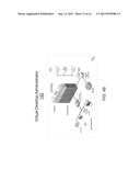
[0028] FIG. 4B shows the virtual desktop administrator 142 which may create and manage virtual desktops. The virtual desktop administrator 142 may allow the user to customize virtual desktops.
[0029] The hardware components 150 shown in FIG. 1 may be provided by the service provider or another entity. The hardware components 150 may include servers 151 and storage 152. The hardware components 150 are the hardware resources operating as platforms for the services delivered to users. The hardware components 150 host the VMs and virtual desktops.
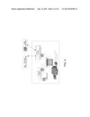
[0030] FIG. 5 shows an example of using the cloud services system 100 to provide services to different types of users, including end users/small businesses, large enterprises and internal users. Also, the cloud services system 100 may be implemented via a public cloud or an internal cloud for an organization and its users.
[0031] The cloud services system 100 may be extended to include software as a service (SaaS) and platform as a service (PaaS) services. Also, different business models may be used for the cloud services system 100. Some business models may include provide cloud services to users, such as small businesses, end users, and large enterprises, in a pay-per-use arrangement. Other models may include providing cloud services to wholesalers, extend cloud services through partners, include additional services from federated cloud providers, or provide cloud services via brokering services.
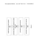
[0032] FIG. 6 shows a flow chart of a method 600 that may be implemented by the cloud services system 100. At 601, the layers of the cloud services system 100 are installed on a computing platform and executed, for example, by a telecommunications provider. At 602, the access services layer provides users with access to order services. At 603, the cloud service manager 130 facilitates provisioning of the ordered service. At 604, the service platform layer 140 provisions virtual servers and virtual desktops for the ordered services.
[0033] Some or all of the methods and operations and functions described above may be provided as machine readable instructions, such as computer programs, stored on a computer readable storage medium, which may be non-transitory such as hardware storage devices or other types of storage devices. For example, they may exist as program(s) comprised of program instructions in source code, object code, executable code or other formats. An example of computer readable storage media includes a RAM, ROM, EPROM, EEPROM, hard drivers, etc.
[0034] Referring to FIG. 7, there is shown a computer system 700 that may be a computer platform for executing the cloud services system 100. It is understood that the illustration of the computer system 700 is a generalized illustration and that the computer system 700 may include additional components and that some of the components described may be removed and/or modified.
[0035] The computer system 700 includes processor(s) 701, such as a central processing unit, ASIC or other type of processing circuit; I/O devices 702, such as a monitor and/or keyboard; a network interface 703, such as a network interface to a Local Area Network (LAN), a wireless 802.11x LAN, a 3G or 4G mobile WAN or a WiMax WAN; and a computer-readable medium 704. Each of these components may be operatively coupled to a bus 708. A computer readable medium (CRM), such as CRM 704 may be any suitable medium which participates in providing instructions to the processor(s) 701 for execution. For example, the CRM 704 may be non-transitory or non-volatile media, such as a magnetic disk or solid-state non-volatile memory or volatile media such as RAM. The instructions stored on the CRM 704 may include machine readable instructions executed by the processor 701 to perform the methods and functions of the cloud services system 100.
[0036] While the embodiments have been described with reference to examples, those skilled in the art will be able to make various modifications to the described embodiments without departing from the scope of the claimed embodiments.
User Contributions:
Comment about this patent or add new information about this topic:
Images included with this patent application:
 |  |
 |  |
 |  |
 |  |
 |  |
 |  |
 |  |
| Similar patent applications: | |
| Date | Title |
|---|---|
| 2013-03-07 | Cloud service monitoring system |
| 2013-06-27 | Cloud-based video surveillance management system |
| 2013-01-10 | Communication service system |
| 2013-06-27 | Transaction services management system |
| 2013-06-27 | Transaction services data system |
| New patent applications in this class: | |
| Date | Title |
|---|---|
| 2022-05-05 | Interface circuit for providing extension packet and processor including the same |
| 2022-05-05 | Deriving an operating system identity |
| 2022-05-05 | Methods and apparatus for online test taking |
| 2022-05-05 | Methods and apparatuses for expanding targets of creatives based on signatures |
| 2022-05-05 | Relay apparatus and relay method |
| Top Inventors for class "Electrical computers and digital processing systems: multicomputer data transferring" | |
| Rank | Inventor's name |
|---|---|
| 1 | International Business Machines Corporation |
| 2 | Jeyhan Karaoguz |
| 3 | International Business Machines Corporation |
| 4 | Christopher Newton |
| 5 | David R. Richardson |