Patent application title: HEAT PIPE STRUCTURE
Inventors:
Chun-Ming Wu (New Taipei City, TW)
Chun-Ming Wu (New Taipei City, TW)
IPC8 Class: AF28D1504FI
USPC Class:
16510426
Class name: Liquid fluent heat exchange material utilizing change of state utilizing capillary attraction
Publication date: 2013-08-22
Patent application number: 20130213609
Abstract:
A heat pipe structure includes a main body having a chamber. The chamber
has a first side and a second side. A first capillary structure and a
second capillary structure are respectively disposed on the first and
second sides. A working fluid is filled in the chamber. The first
capillary structure has a volume larger than a volume of the second
capillary structure but smaller than one half of a circumference of inner
wall face of the chamber. The first and second capillary structures are
connected with each other. The first and second capillary structures and
the inner wall face of the chamber together define at least one vapor
passage. By means of the heat pipe structure, the amount of transferred
heat is increased and the heat transfer efficiency is greatly enhanced.Claims:
1. A heat pipe structure comprising a main body having a chamber, the
chamber having a first side and a second side, a first capillary
structure and a second capillary structure being respectively disposed on
the first and second sides, a working fluid being filled in the chamber,
the first capillary structure having a volume larger than a volume of the
second capillary structure, the first and second capillary structures
being connected with each other, the first and second capillary
structures and inner wall face of the chamber together defining at least
one vapor passage.
2. The heat pipe structure as claimed in claim 1, wherein the volume of the first capillary structure is smaller than one half of a circumference of the inner wall face of the chamber.
3. The heat pipe structure as claimed in claim 1, wherein an outer face of the first side of the chamber is correspondingly attached to at least one heat source for conducting heat, at least one heat dissipation unit being correspondingly disposed on an outer face of the second side, the heat dissipation unit being selected from a group consisting of a heat sink, a radiating fin assembly and a water-cooled unit.
4. The heat pipe structure as claimed in claim 1, wherein the first and second capillary structures are selected from a grouping consisting of sintered powder bodies, mesh bodies and fiber bodies.
5. The heat pipe structure as claimed in claim 1, wherein the first capillary structure has a first extension section extending from one side of the first capillary structure, the first extension section being connected with the second capillary structure.
6. The heat pipe structure as claimed in claim 1, wherein the second capillary structure has a second extension section extending from one side of the second capillary structure, the second extension section being connected with the first capillary structure.
7. The heat pipe structure as claimed in claim 1, wherein the inner wall face of the chamber is a smooth wall face.
8. The heat pipe structure as claimed in claim 1, wherein a third capillary structure is disposed on the inner wall face of the chamber, the first and second capillary structures being connected with the third capillary structure.
9. The heat pipe structure as claimed in claim 8, wherein the third capillary structure is selected from a grouping consisting of a sintered powder body, a mesh body, a fiber body and a structure formed with multiple channels.
10. The heat pipe structure as claimed in claim 1, wherein the first capillary structure has a radial extension volume larger than a radial extension volume of the second capillary structure.
11. The heat pipe structure as claimed in claim 2, wherein an outer face of the first side of the chamber is correspondingly attached to at least one heat source for conducting heat, at least one heat dissipation unit being correspondingly disposed on an outer face of the second side, the heat dissipation unit being selected from a group consisting of a heat sink, a radiating fin assembly and a water-cooled unit.
12. The heat pipe structure as claimed in claim 2, wherein the first and second capillary structures are selected from a grouping consisting of sintered powder bodies, mesh bodies and fiber bodies.
13. The heat pipe structure as claimed in claim 2, wherein the first capillary structure has a first extension section extending from one side of the first capillary structure, the first extension section being connected with the second capillary structure.
14. The heat pipe structure as claimed in claim 2, wherein the second capillary structure has a second extension section extending from one side of the second capillary structure, the second extension section being connected with the first capillary structure.
15. The heat pipe structure as claimed in claim 2, wherein the inner wall face of the chamber is a smooth wall face.
16. The heat pipe structure as claimed in claim 2, wherein a third capillary structure is disposed on the inner wall face of the chamber, the first and second capillary structures being connected with the third capillary structure.
17. The heat pipe structure as claimed in claim 16, wherein the third capillary structure is selected from a grouping consisting of a sintered powder body, a mesh body, a fiber body and a structure formed with multiple channels.
18. The heat pipe structure as claimed in claim 2, wherein the first capillary structure has a radial extension volume larger than a radial extension volume of the second capillary structure.
Description:
BACKGROUND OF THE INVENTION
[0001] 1. Field of the Invention
[0002] The present invention relates generally to a heat pipe structure, and more particularly to a heat pipe structure, which is able to reduce thermal impedance pressure and greatly enhance the vapor-liquid circulation of the working fluid in the heat pipe and increase the heat transfer efficiency.
[0003] 2. Description of the Related Art
[0004] There is a more and more obvious trend to miniaturization of all kinds of high-performance computers, intelligent electronic devices and other electrical equipments. To catch up this trend, the heat transfer components and heat dissipation components used in these devices have also been more and more miniaturized and thinned to meet the requirements of users.
[0005] It is known that heat pipe is a heat transfer component with excellent thermal conductivity. The thermal conductivity of the heat pipe is several times to several tens times the thermal conductivity of copper, aluminum or the like. Therefore, the heat pipe is used as a cooling component and applied to various electronic devices.
[0006] As to the configuration, the conventional heat pipes can be classified into heat pipes in the form of circular tubes, heat pipes with D-shaped cross sections and flat-plate heat pipes. The heat pipes are mainly used to conduct the heat generated by the heat sources in the electronic devices and cool the heat sources. Currently, in view of easy installation and larger contact area, flat-plate heat pipes are widely used for cooling the heat sources. Following the miniaturization of the cooling mechanism, various flat-plate heat pipes are widely applied to the electronic devices for conducting the heat generated by the heat-generating components.
[0007] The conventional heat pipe structure can be manufactured by means of many kinds of methods. For example, the heat pipe can be manufactured in such a manner that metal powder is filled into a hollow tubular body and sintered to form a capillary structure layer on the inner wall face of the tubular body. Then the tubular body is vacuumed and filled with a working fluid and then sealed. Alternatively, a metal-made mesh body is placed into the tubular body. The mesh capillary structure body will naturally outward stretch and expand to attach to the inner wall face of the tubular body to form a capillary structure layer. Then the tubular body is vacuumed and filled with a working fluid and then sealed. To meet the requirements for miniaturization and thinning of the electronic devices, the heat pipe needs to be manufactured with the form of a flat plate.
[0008] The flat-plate heat pipe can achieve object of thinning. However, this leads to another problem. That is, in the flat-plate heat pipe, the metal powder is sintered to form a capillary structure layer fully coated on the inner wall face of the heat pipe. When compressing the flat-plate heat pipe, the capillary structure, (that is, the sintered metal powder or mesh capillary structure body) in the flat-plate heat pipe on two sides of the compressed faces is likely to be squeezed and damaged. In this case, the capillary structure tends to peel off from the inner wall face of the flat-plate heat pipe. This will greatly deteriorate the heat transfer performance of the thin heat pipe or even make the thin heat pipe lose its function. Moreover, although the flat-plate heat pipe can conduct the heat, after thinned and flattened, the internal capillary structure of the flat-plate heat pipe will have insufficient capillary attraction. As a result, the working fluid will block the vapor passage. Furthermore, after thinned, the area of the flow passage inside the flat-plate heat pipe is reduced so that the capillary attraction is lowered. As a result, the maximum heat transfer amount is lowered. On one hand, this is mainly because after thinned, the internal capacity of the flat-plate heat pipe is reduced and on the other hand, this is because after flattened, the central section of the flat-plate heat pipe is recessed to narrow or even block the vapor passage.
[0009] To solve the above problems existing in the conventional heat pipe, some manufacturers in this field insert a core bar into the internal chamber of the flat-plate heat pipe. The core bar is formed with a specific axial cut. Metal powder is filled into the space defined by the cut and the inner wall face of the chamber. Then the metal powder is sintered to form a capillary structure at the central section of the chamber. Then the core bar is extracted out. Then the central section of the chamber is compressed and flattened. The capillary structure thermally contacts the plane parts of the inner wall face of the chamber. In addition, voids are formed on two sides of the capillary structure in the chamber to serve as the vapor passages. Accordingly, better vapor passage impedance is achievable. However, the cross-sectional area of the capillary structure is quite narrow so that the capillary attraction is lowered. As a result, the anti-gravity thermal efficiency and heat transfer efficiency are poor.
SUMMARY OF THE INVENTION
[0010] A primary object of the present invention is to provide a heat pipe structure, which is able to increase heat conduction efficiency and heat transfer efficiency.
[0011] A further object of the present invention is to provide the above heat pipe structure, which is able to reduce thermal impedance pressure.
[0012] To achieve the above and other objects, the heat pipe structure of the present invention includes a main body having a chamber. The chamber has a first side and a second side. A first capillary structure and a second capillary structure are respectively disposed on the first and second sides. A working fluid is filled in the chamber. The first capillary structure has a volume larger than the volume of the second capillary structure but smaller than one half of the circumference of inner wall face of the chamber. The first and second capillary structures are connected with each other. The first and second capillary structures and the inner wall face of the chamber together define at least one vapor passage.
[0013] By means of the heat pipe structure, the thermal impedance pressure of the heat pipe is greatly reduced and the vapor-liquid circulation efficiency of the working fluid in the heat pipe is enhanced. According to the above, the heat pipe structure of the present invention has the following advantages:
[0014] 1. The heat pipe structure of the present invention can bear greater thermal power impact per unit area.
[0015] 2. The heat pipe structure of the present invention can increase the maximum heat transfer efficiency.
[0016] 3. The heat pipe structure of the present invention has better anti-gravity performance.
[0017] 4. The heat pipe structure of the present invention has smaller interface thermal resistance.
BRIEF DESCRIPTION OF THE DRAWINGS
[0018] The structure and the technical means adopted by the present invention to achieve the above and other objects can be best understood by referring to the following detailed description of the preferred embodiments and the accompanying drawings, wherein:
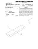
[0019] FIG. 1 is a perspective view of a first embodiment of the heat pipe structure of the present invention;
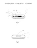
[0020] FIG. 2 is a sectional view taken along line A-A of FIG. 1;
[0021] FIG. 3 is a sectional view of a second embodiment of the heat pipe structure of the present invention;
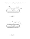
[0022] FIG. 4 is a sectional view of a third embodiment of the heat pipe structure of the present invention;
[0023] FIG. 5 is a sectional view of a fourth embodiment of the heat pipe structure of the present invention;
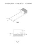
[0024] FIG. 6 is a perspective view showing the application of the heat pipe structure of the present invention; and
[0025] FIG. 7 is a sectional view showing the application of the heat pipe structure of the present invention.
DETAILED DESCRIPTION OF THE PREFERRED EMBODIMENTS
[0026] Please refer to FIGS. 1 and 2. FIG. 1 is a perspective view of a first embodiment of the heat pipe structure of the present invention. FIG. 2 is a sectional view taken along line A-A of FIG. 1. According to the first embodiment, the heat pipe structure of the present invention includes a main body 1 having a chamber 11. The chamber 11 has a first side 111 and a second side 112. A first capillary structure 1121 and a second capillary structure 1122 are respectively disposed on the first and second sides 111, 112. A working fluid 2 is filled in the chamber 11. The first capillary structure 1121 has a volume larger than the volume of the second capillary structure 1122, (that is, a radial extension volume of the first capillary structure 1121 is larger than a radial extension volume of the second capillary structure 1122) but smaller than one half of a circumference of inner wall face of the chamber 11. The first and second capillary structures 1121, 1122 are connected with each other. The first and second capillary structures 1121, 1122 and the inner wall face of the chamber 11 together define at least one vapor passage 113.
[0027] The first and second capillary structures 1121, 1122 are selected from a grouping consisting of sintered powder bodies, mesh bodies and fiber bodies. In this embodiment, the first and second capillary structures 1121, 1122 are, but not limited to, sintered powder bodies for illustration purposes only. The inner wall face of the chamber 11 is a smooth wall face.
[0028] Please now refer to FIG. 3, which is a sectional view of a second embodiment of the heat pipe structure of the present invention. The second embodiment is partially identical to the first embodiment in structure and thus will not be repeatedly described hereinafter. The second embodiment is different from the first embodiment in that the first capillary structure 1121 has a first extension section 1123 extending from one side of the first capillary structure 1121. The first extension section 1123 is connected with the second capillary structure 1122.
[0029] Please now refer to FIG. 4, which is a sectional view of a third embodiment of the heat pipe structure of the present invention. The third embodiment is partially identical to the first embodiment in structure and thus will not be repeatedly described hereinafter. The third embodiment is different from the first embodiment in that the second capillary structure 1122 has a second extension section 1124 extending from one side of the second capillary structure 1122. The second extension section 1124 is connected with the first capillary structure 1121.
[0030] Please now refer to FIG. 5, which is a sectional view of a fourth embodiment of the heat pipe structure of the present invention. The fourth embodiment is partially identical to the first embodiment in structure and thus will not be repeatedly described hereinafter. The fourth embodiment is different from the first embodiment in that a third capillary structure 1125 is disposed on the inner wall face of the chamber 11. The first and second capillary structures 1121, 1122 are connected with the third capillary structure 1125. The third capillary structure 1125 is selected from a grouping consisting of a sintered powder body, a mesh body, a fiber body and a structure formed with multiple channels. In this embodiment, the third capillary structure 1125 is, but not limited to, a structure formed with multiple channels for illustration purposes only.
[0031] Please now refer to FIGS. 6 and 7. FIG. 6 is a perspective view showing the application of the heat pipe structure of the present invention. FIG. 7 is a sectional view showing the application of the heat pipe structure of the present invention. As shown in FIGS. 6 and 7, an outer face of the first side 111 of the main body 1 is correspondingly assembled with at least one heat source 3 positioned at one end of the main body 1. An outer face of the second side 112 is correspondingly assembled with at least one heat dissipation unit 4 disposed at the other end of the main body 1 opposite to the end at which the heat source 3 is positioned. The heat dissipation unit 4 is selected from a group consisting of a heat sink, a radiating fin assembly and a water-cooled unit. In this embodiment, the heat dissipation unit 4 is, but not limited to, a heat sink for illustration purposes only.
[0032] In this embodiment, the first capillary structure 1121 of the main body 1 has a total volume larger than that of the second capillary structure 1122. The first capillary structure 1121 is disposed on the first side 111 of the main body 1 in contact with the heat source 3. The second capillary structure 1122 is disposed on the second side 112 of the main body 1 opposite to the first side 111. The working fluid 2 in the first capillary structure 1121 will absorb the heat generated by the heat source 3 and evaporate. Accordingly, the liquid working fluid 22 will be converted into vapor working fluid 21 to spread to the second side 112 of the main body 1. The vapor working fluid 21 is condensed into liquid working fluid 22 on the second side 112. The liquid working fluid 22 flows back to the first capillary structure 1121 via gravity or the capillary attraction of the second capillary structure 1122 to continue the vapor-liquid circulation. After the working fluid 2 is converted from liquid phase to vapor phase, the vapor working fluid 21 spreads from the first side 111 to the second side 112 through the vapor passage 113 of the main body 1. The volume of the second capillary structure 1122 is smaller than the volume of the first capillary structure 1121. Therefore, the pressure impedance against the spreading of the vapor working fluid 21 is reduced. Accordingly, not only the radial heat conduction efficiency of the main body 1 can be increased, but also the axial heat conduction efficiency of the main body 1 can be greatly enhanced. Therefore, the vapor-liquid circulation efficiency of the working fluid 2 in the main body 1 is effectively increased.
[0033] The above embodiments are only used to illustrate the present invention, not intended to limit the scope thereof. It is understood that many changes and modifications of the above embodiments can be made without departing from the spirit of the present invention. The scope of the present invention is limited only by the appended claims.
User Contributions:
Comment about this patent or add new information about this topic:
| People who visited this patent also read: | |
| Patent application number | Title |
|---|---|
| 20130213186 | APPARATUS FOR REMOVING AND INSTALLING ELEVATED LIGHT BULBS |
| 20130213185 | ADJUSTABLE GRIPPING TOOL |
| 20130213184 | Process For Making Low and Specified Hardenability Structural Steel |
| 20130213183 | ARRANGEMENT FOR AN INTERNAL COMBUSTION ENGINE |
| 20130213182 | ARRANGEMENT FOR AN INTERNAL COMBUSTION ENGINE |
Images included with this patent application:
 |  |
 |  |
 |
| Similar patent applications: | |
| Date | Title |
|---|---|
| 2009-03-19 | Heat pipe structure |
| 2011-04-21 | Heat pipe structure |
| 2012-07-19 | Heat pipe structure |
| 2012-10-04 | Loop heat pipe structure |
| 2013-02-14 | Thin-type heat pipe structure |
| New patent applications in this class: | |
| Date | Title |
|---|---|
| 2019-05-16 | Method for preparing porous wick and product prepared by the same |
| 2019-05-16 | Semiconductor device assembly with vapor chamber |
| 2019-05-16 | Straight-through structure of heat dissipation unit |
| 2018-01-25 | Diphasic cooling loop with satellite evaporators |
| 2017-08-17 | Heat pipe |
| New patent applications from these inventors: | |
| Date | Title |
|---|---|
| 2016-05-12 | Emi shielding structure for electronic components |
| 2016-05-12 | Display module with heat dissipation structure and handheld device thereof |
| 2016-05-12 | Heat dissipation structure of wearable electronic device |
| 2016-05-12 | Heat dissipation structure of wearable watchstrap |
| 2016-05-12 | Thin heat pipe structure |
| Top Inventors for class "Heat exchange" | |
| Rank | Inventor's name |
|---|---|
| 1 | Levi A. Campbell |
| 2 | Chun-Chi Chen |
| 3 | Tai-Her Yang |
| 4 | Robert E. Simons |
| 5 | Richard C. Chu |