Patent application title: Heat Sink and Fins Thereof
Inventors:
Shyh-Ming Chen (New Taipei City, TW)
IPC8 Class: AF28F700FI
USPC Class:
165185
Class name: Heat exchange heat transmitter
Publication date: 2013-05-16
Patent application number: 20130118725
Abstract:
The heat sink of the invention includes a cylinder and fins fastened
thereto. A hollow in the cylinder is for receiving a heat source. Each
the fin includes two parallel wings and a connection plate therebetween.
A space is defined by the two wings and the connection plate for air
flow.Claims:
1. A heat dissipation fin comprising: two parallel wings; and a
connection plate between the two wings; wherein a space is defined by the
two wings and the connection plate.
2. The heat dissipation fin of claim 1, wherein the connection plate is formed with a through hole.
3. The heat dissipation fin of claim 1, wherein at least one of the wings is formed with a passing hole.
4. The heat dissipation fin of claim 1, wherein tops of the wings are separately formed with connecting portions for fastening to a lamp head.
5. The heat dissipation fin of claim 1, wherein bottoms of the wings are separately formed with engaging portions for fastening to a frame.
6. The heat dissipation fin of claim 1, wherein the connection plate has an open area.
7. The heat dissipation fin of claim 1, wherein the connection plate is a plane in shape.
8. A heat sink comprising: a cylinder; and fins, fastened onto an outer surface of the cylinder, each the fin comprising: two parallel wings; and a connection plate between the two wings; wherein a space is defined by the two wings and the connection plate.
9. The heat sink of claim 8, wherein the connection plate is formed with a through hole.
10. The heat sink of claim 8, wherein at least one of the wings is formed with a passing hole.
11. The heat sink of claim 8, wherein tops of the wings are separately formed with connecting portions for fastening to a lamp head.
12. The heat sink of claim 8, wherein bottoms of the wings are separately formed with engaging portions for fastening to a frame.
13. The heat sink of claim 8, wherein the connection plate has an open area.
14. The heat sink of claim 8, wherein the cylinder is formed with grooves to separately engage with the fins.
15. The heat sink of claim 14, wherein inner edges of the wings are separately engaged in the grooves.
16. The heat sink of claim 14, wherein the cylinder is formed with guide slots, and each the guide slot is between every two adjacent grooves.
17. The heat sink of claim 8, wherein the connection plate is a plane in shape.
18. The heat sink of claim 8, further comprising a cover on the cylinder.
19. The heat sink of claim 18, wherein the cover is a slice made of plastic or metal.
Description:
BACKGROUND OF THE INVENTION
[0001] 1. Technical Field
[0002] The invention relates to heat sinks, particularly to combinative heat sinks.
[0003] 2. Related Art
[0004] Light emitting diodes (LEDs) have been replacing conventional lighting. Because power of the LEDs becomes higher and higher, the heat generated from the LEDs also upswings. High heat not only makes the LEDs easy to damage, but also tends to cause scalds. As a result, high power LEDs need heat sinks with high efficiency of heat dissipation.
SUMMARY OF THE INVENTION
[0005] An object of the invention is to provide a heat sink and fins thereof, which can increase heat dissipating area, enhance efficiency of heat dissipation, reinforce the structure and improve the extent of safety.
[0006] To accomplish the above object, the heat sink of the invention includes a cylinder and fins fastened thereto. A hollow in the cylinder is for receiving a heat source. Each the fin includes two parallel wings and a connection plate therebetween. A space is defined by the two wings and the connection plate.
BRIEF DESCRIPTION OF THE DRAWINGS
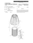
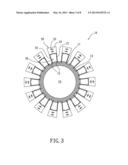
[0007] FIG. 1 is a perspective view of the invention;
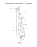
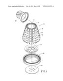
[0008] FIG. 2 is an exploded view of the invention;
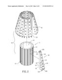
[0009] FIG. 3 is a top view of the invention;
[0010] FIG. 4 is a schematic view showing the invention connected with a heat source;
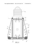
[0011] FIG. 5 is a sectional view of FIG. 4;
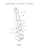
[0012] FIG. 6 shows another embodiment of the single fin of the invention;
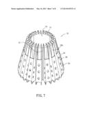
[0013] FIG. 7 is a perspective view of the heat sink with the fins shown in FIG. 6; and
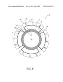
[0014] FIG. 8 shows still another embodiment of the invention.
DETAILED DESCRIPTION OF THE INVENTION
[0015] Please refer to FIGS. 1-3. The heat sink 10 includes a cylinder 11 and a plurality of fins 20. An outer surface of the cylinder 11 is formed with grooves 12 for engaging with the fins 20 and guide slots 13 between every two adjacent grooves 12 for being pressed by a press mold (not shown) to make the grooves 12 grip the fins 20. A hollow 14 formed in the cylinder 11 is used for receive a heat source such as an LED module as shown in FIGS. 4 and 5. Each of the fins 20 is composed of two parallel wings 21, 22 and a connection plate 23 connecting therebetween. The connection plate 23 may be a plane or non-plane such as a segment or folded plate. Inner sides of the wings 21, 22 are inserted into the grooves 12. The grooves 12 will be deformed to grip the wings 21, 22 when the press mold has pressed the guide slots.
[0016] Each of the wings 21, 22 of the fins 20 is provided with at least one through hole 24 (three through holes are shown in the figures). And the connection plate 23 is provided with three passing holes 25. The space defined by the wings 21, 22 and the connection plate 23 can serve as an air passage 26 to allow air to flow therein.
[0017] Please refer to FIGS. 1, 2 and 4. The tops and bottoms of the wings 21, 22 of the heat sink 10 are formed with connecting portions 211, 221 for fastening to a lamp head 30 and engaging portions 212, 222 for fastening to a frame 40, respectively. Thus this assembly can form an LED lamp. Furthermore, the invention includes a cover 50 which is a slice made of plastic or metal. The cover 50 is fastened within the frame 40 for prevent dirt or dusts from entering the heat sink 10.
[0018] Please refer to FIGS. 6 and 7, which show another embodiment of the invention. This embodiment differs from the above embodiment by the connection plate 23a with an open area 23b at the top thereof. The open area 23b allows air to flow through for heat convection.
[0019] FIG. 8 shows still another embodiment of the invention. This embodiment differs from the above embodiments by the wider fins 20. The wider fins 20 can reduce the quantity required. As shown, only four (but not limited to) wider fins 20 fastened to the cylinder 11 can form a heat sink.
[0020] While the forgoing is directed to preferred embodiments of the present invention, other and further embodiments of the invention may be devised without departing from the basic scope thereof. As such, the appropriate scope of the invention is to be determined according to the claims.
User Contributions:
Comment about this patent or add new information about this topic:
| People who visited this patent also read: | |
| Patent application number | Title |
|---|---|
| 20190098056 | REST-BASED DECLARATIVE POLICY MANAGEMENT |
| 20190098055 | REST-BASED DECLARATIVE POLICY MANAGEMENT |
| 20190098054 | Tag-Based Security Policy Creation in a Distributed Computing Environment |
| 20190098053 | SECONDARY COMMUNICATION CHANNEL FOR SECURITY NOTIFICATIONS |
| 20190098052 | APPARATUS INCLUDING SECURE COMPONENT AND METHOD OF PROVISIONING SECURITY INFORMATION INTO THE APPARATUS |
Images included with this patent application:
 |  |
 |  |
 |  |
 |  |
 |
| Similar patent applications: | |
| Date | Title |
|---|---|
| 2014-07-10 | Capillary device for use in heat pipe and method of manufacturing such capillary device |
| 2012-08-30 | Heat sink fastener |
| 2013-01-24 | Heat sink adaptor |
| 2013-02-21 | Heat sinking plate |
| 2009-06-04 | Heat sink device |
| New patent applications from these inventors: | |
| Date | Title |
|---|---|
| 2013-03-07 | Lamp seat structure |
| 2013-02-21 | Heat sink |
| 2011-09-01 | Heat sink |
| Top Inventors for class "Heat exchange" | |
| Rank | Inventor's name |
|---|---|
| 1 | Levi A. Campbell |
| 2 | Chun-Chi Chen |
| 3 | Tai-Her Yang |
| 4 | Robert E. Simons |
| 5 | Richard C. Chu |