Patent application title: Controlling Method, Power Supply, Power Controller, and Power Controlling Method
Inventors:
Yu-Yun Huang (New Taipei City, TW)
IPC8 Class: AH02M322FI
USPC Class:
363 15
Class name: Electric power conversion systems current conversion including d.c.-a.c.-d.c. converter
Publication date: 2013-03-21
Patent application number: 20130070483
Abstract:
A power supply has an inductor and determines loading state of the power
supply according to a compensation signal. When the loading state is
determined to be a light loading state or a no-loading state, a switch is
operated at a low operating frequency. When the loading state is
determined to be a heavy loading state, the switch is operated at a high
operating frequency. If the compensation signal exceeds a critical value,
it is determined that the loading state is an overloaded state. When the
overloaded state continues past a tolerable duration, the switch is
turned off. The tolerable duration is determined by an external capacitor
and is independent of the operating frequency.Claims:
1. A controlling method utilized in a power supply comprising a switch
and an inductive element, the controlling method comprising: detecting an
inductive current flowing through the inductive element; determining the
power supply under a normal loading state or an overloaded state
according to a feedback signal; controlling a peak of the inductive
current to be smaller than or equal to a constant magnitude and
controlling the switch to be operated in a first frequency when the power
supply is operated under the normal loading state; controlling the peak
of the inductive current to be approximately the constant magnitude and
controlling the switch to be operated in a second frequency when the
power supply is operated under the overloaded state, wherein the second
frequency is higher than the first frequency; calculating a duration
during which the power supply is operated under the overloaded state; and
stopping the inductive current when the duration exceeds a tolerable
duration; wherein the tolerable duration is independent of variation of
the operating frequency.
2. The controlling method of claim 1 further comprising: adapting the operating frequency according to the feedback signal.
3. The controlling method of claim 1 further comprising: resetting a counter for calculating the duration when the power supply leaves the overloaded state.
4. The controlling method of claim 1 further comprising: providing a clock generator to generate the operating frequency; wherein the tolerable duration is independent of the operating frequency.
5. A power supply comprising: a controller, for controlling an inductive current flowing through an inductive element, the controller comprising: a clock generator for generating an operating frequency; a current limiter for controlling a peak of the inductive current to be approximately a constant magnitude, wherein when the current limiter controls the peak to be approximately the constant magnitude, the operating frequency is lower than or equal to a first frequency; and an overloading limiter comprising: an overloading identifier for identifying whether the power supply should enter an overloaded state according to a feedback signal, wherein when the power supply is operated in the overloaded state, the operating frequency is a second frequency higher than the first frequency; and a current supply, for providing a charging/discharging current to an external capacitor and for calculating a duration during which the power supply is operated in the overloaded state; wherein when the duration exceeds a tolerable duration, the controller stops the inductive current, and the tolerable duration is independent from variation of the operating frequency.
6. A power controller utilized for a power supply comprising an inductive element and a switch, the power controller comprising: a first comparator, for receiving a compensation signal and a current detection signal to control the switch, wherein the current detection signal corresponds to an inductive current flowing through the inductive element, the compensation signal corresponds to a loading state of the power supply, and the first comparator is utilized for approximately determining a peak of the inductive current according to the compensation signal; a clock generator, for roughly providing an operating frequency of the switch according to the compensation signal, wherein the operating frequency is a high operating frequency when the loading state is a heavy loading state and the operating frequency is a low operating frequency when the loading state is a light loading state or a no-loading state; and an overloading limiter, comprising a charge/discharge device coupled to an external capacitor, for detecting the compensation signal to determine whether an overload event occurs, and for outputting an overload limiting signal to turn off the switch when a tolerable duration is exceeded after the overload event occurs; wherein the external capacitor and the charge/discharge device forming a clock oscillator, and the tolerable duration is determined by the external capacitor and independent of the clock oscillator.
7. The power controller of claim 6 wherein the overloading limiter further comprises: a second comparator, for comparing the feedback signal with a critical signal and outputting an overload signal indicating the overload event occurred if the compensation signal is higher than the critical signal; and a counter coupled to the second comparator, for receiving a clock signal and starting to count when the comparator outputs the overload signal; wherein the overload limiting signal is outputted after an the overload signal outputted from the counter fulfills a condition.
8. The power controller of claim 7, wherein a frequency of the clock signal is determined by both the external capacitor and the charge/discharge device, and the tolerable duration is related to both the condition and the frequency of the clock signal.
9. The power controller of claim 6, wherein the clock oscillator determines the operating frequency to be an overloaded frequency higher than the high operating frequency within the tolerable duration after the occurrence of the overloading event.
10. The power controller of claim 6 further comprising: a peak limiter, for detecting the current detection signal and outputting a peak limiting signal to control the switch, and thereby approximately limiting the peak of the inductive current to be a limit peak.
11. The power controller of claim 10, wherein the peak of the inductive current is the limit peak within the tolerable duration after the occurrence of the overload event.
12. A power controlling method utilized for a power supply, the power supply comprising an inductive element and a switch, the power controlling method comprising: determining a loading state of the power supply according to a compensation signal, controlling the switch to be operated under a high operating frequency when the loading state is a heavy loading state, and controlling the switch to be operated under a low operating frequency when the loading state is a light loading state or a no-loading state; and determining the loading state to be an overloaded state when the compensation signal exceeds a critical value, and turning off the switch when the overloaded state lasts beyond a tolerable duration; wherein the tolerable duration is determined according to an external capacitor and is independent of both the high and low operating frequencies for operating the switch.
13. The power controlling method of claim 12 wherein the switch is controlled to be operated under an overloaded frequency higher than the high operating frequency within the tolerable duration when the loading state is the overloaded state.
14. The power controlling method of claim 12 further comprising: detecting an inductive current flowing through the inductive element for generating a current detection signal; and roughly determining a peak of the inductive current according to both the compensation signal and the current detection signal.
15. The power controlling method of claim 14 further comprising: providing a limit signal for limiting a peak of the inductive current to approximately be a limit peak; wherein the peak of the inductive current is limited to be the limit peak within the tolerable duration after the compensation signal exceeds the critical value.
16. A power controlling method utilized for a power supply, the power supply comprising an inductive element and being controlled by a switch to charge or discharge for generating an output power, the power controlling method comprising: providing a clock generator for roughly providing an operating frequency of the switch; detecting a loading state of the power supply; adjusting the operating frequency according to the loading state, wherein the operating frequency is a first frequency when the loading state is a heavy loading state; controlling the operating frequency to approximately be a second frequency higher than the first frequency within a tolerable duration when the loading state is an overloaded state; and ceasing operations of the switch after the tolerable duration is exceeded; wherein the tolerable duration is independent of a clock oscillator.
17. The power controlling method of claim 16 further comprising: providing a compensation signal according to a voltage level of the output power; wherein detecting the loading state of the power supply comprises: comparing the compensation signal with a critical signal, and determining the loading state to be the overloaded state when the compensation signal is higher than the critical signal.
Description:
BACKGROUND OF THE INVENTION
[0001] 1. Field of the Invention
[0002] The present invention is related to an overloading limitation of a switched-mode power supply (SMPS).
[0003] 2. Description of the Prior Art
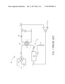
[0004] A power supply is a kind of power management device that transforms power from a power source to provide transformed power to an electronic device or component. FIG. 1 illustrates conventional power supply 60, which employs a flyback topology. In FIG. 1, bridge rectifier 62 is utilized for rectifying AC power VAC to provide input power VIN to transformer 64. When switch 72 is close-circuited, primary winding LP of transformer 64 is charged. When switch 72 is open-circuited, secondary winding Ls of transformer 64 discharges to load capacitor 69 via rectifier 66 to generate output power VOUT. Error amplifier EA compares voltage levels of output power VOUT and target voltage VTARGET to generate a compensation signal VCOM. Controller 74 controls switch 72 with the aid of control signal VGATE according to both compensation signal VCOM and current detection signal VCS, which correspond to inductive current flowing through primary winding LP.
[0005] Many types of protection may be added to power supply 60, including over-voltage protection (OVP), over-temperature protection (OTP), and overload protection (OLP). Overload protection is used when output current loading of power supply 60 is too high, and when the power supply provides power exceeding a predetermined output power level.
[0006] Overload protection may be implemented by limiting output current, or by limiting the inductive current flowing through primary winding LP. Both implementations are intended to prevent power outputted by the power supply from exceeding a certain level.
BRIEF DESCRIPTION OF THE DRAWINGS
[0007] FIG. 1 illustrates a conventional power supply acquiring a flyback topology.
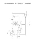
[0008] FIG. 2 illustrates a power supply according to an embodiment of the present invention.
[0009] FIG. 3 illustrates part of the controller and the external capacitor shown in FIG. 2.
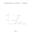
[0010] FIG. 4 illustrates a correspondence between the operating frequency generated by the clock generator and the compensation signal.
DETAILED DESCRIPTION
[0011] Please refer to FIG. 2, which illustrates power supply 90 according to an embodiment of the present invention. Similar reference numerals are used in FIG. 1 and FIG. 2 to indicate same elements, same devices, or same signals, and are not described repeatedly for brevity. Embodiments generated by using elements the same as or similar to elements shown in FIG. 1 should be regarded as embodiments of the present invention. Scope of the present invention should also follow claims of the present invention.
[0012] In an embodiment, controller 73 shown in FIG. 2 is implemented by a single integrated circuit. In another embodiment, controller 73 and switch 72 are implemented in a single integrated circuit. A difference between controllers 73 and 74 lies in addition of pin CT of controller 73 shown in FIG. 2, where controller 73 is coupled to external capacitor 75 via pin CT.
[0013] FIG. 3 illustrates part of controller 73 and external capacitor 75 shown in FIG. 2. Comparator 82 is utilized for providing over-current protection, and is a peak limiter for preventing any peak of current detection signal VCS from exceeding voltage VCS -LIMIT. A peak of the inductive current flowing through the primary winding LP is also prevented from exceeding peak current ICS--.sub.LIMIT VCS-LIMIT/RCS), where RCS indicates resistance of resistor CS. Comparator 84 controls an approximate peak of the inductive current flowing through primary winding LP according to compensation signal VCOM. Voltage level of compensation signal VCOM corresponds to power required for sustaining a current output voltage or a loading state related to the current output voltage. Compensation signal VCOM also determines output operating frequency of clock generator 96, i.e. operating frequency of switch 72 shown in FIG. 2. For example, a low voltage level of compensation signal VCOM indicates a light loading state or a no-loading state, so that a corresponding operating frequency may be equal to 20 kHz. A high voltage level of compensation signal VCOM indicates a heavy loading state, so that a corresponding operating frequency may be equal to 65 kHz. The heavy loading state, the light loading state, and the no-loading state are all regarded as normal loading states.
[0014] Current supplier 85 provides a charge/discharge current to external capacitor 75 via pin CT. A combination of current supplier 85 and external capacitor 75 may be regarded as a clock oscillator, i.e. forming a clock oscillator. When the compensation signal VCOM is higher than critical voltage VOLP for overload protection, i.e. when an overload event occurs, power supply 90 is determined to begin operating in an overloaded state, and comparator 88 starts counter 92 counting according to a clock signal outputted by the clock oscillator. Once comparator 94 determines that the output of counter 92 fulfills a predetermined condition, indicating the overload event has continued past a tolerable duration, comparator 94 begins outputting an overload limiting signal for triggering overload protection, and logic control unit 86 keeps switch 72 turned off to stop power transformation and power transmission. If the compensation signal VCOM drops below the critical voltage VOLP before the tolerable duration is exceeded, i.e. when power supply 90 leaves the overloaded state, counter 92 is reset, and switch 72 continues to be operated at the operating frequency provided by clock generator 96. A combination of current provider 85, comparator 88, counter 92, and comparator 94 may be regarded as an overload limiter. In another embodiment of the present invention, comparator 94 is omitted, and whether to trigger overload protection or not is determined directly according to an output bit having value of logical 0 or logical 1.
[0015] It can be seen from the illustration of controller 73 shown in FIG. 3 that the tolerable duration indicates a maximum duration tolerable for power supply 90 to be in the overloaded state, where the tolerable duration is determined according to both the frequency provided by the clock oscillator, which includes at least current provider 85 and external capacitor 75, and a predetermined condition defined by comparator 94. The tolerable duration is independent of variation of the operating frequency generated by clock generator 96. For example, in design, comparator 94 is built in an integrated circuit so that external factors cannot change settings of comparator 94, and the frequency of the clock oscillator can be determined according to capacitance of external capacitor 75. Therefore, the tolerable duration can be easily adjusted by selecting an appropriate capacitance for external capacitor 75.
[0016] In one embodiment of the present invention, after overload protection is triggered, overload protection is de-asserted once compensation signal VCOM drops below critical voltage VOLP, so that power transformation and power transmission are restored. In another embodiment of the present invention, overload protection is de-asserted only when the AC power source of controller 73 is removed and restarted.
[0017] FIG. 4 illustrates a correspondence between the operating frequency generated by clock generator 96 and the compensation signal VCOM. When the voltage level of compensation signal VCOM reaches voltage VCS-LIMIT, i.e. when heavy loading occurs, the operating frequency is adjusted to be heavy-loading frequency fHEAVY, which may be 65 kHz in one embodiment of the present invention. When the voltage level of compensation signal VCOM reaches critical voltage VOLP for overload protection, i.e. when the overloaded state is triggered, the operating frequency is adjusted to be overloaded frequency f.sub.OverLoad, which may be 130 kHz in one embodiment of the present invention. When the peak of the inductive current flowing through primary winding LP is roughly equal to ICS--.sub.LIMIT, the operating frequency is at least heavy-loading frequency fHEAVY. During the tolerable duration, i.e. when compensation signal VCOM is higher than critical voltage VOLP for overload protection, the peak of the inductive current is approximately controlled to be fixed to ICS--.sub.LIMIT, because of the restriction provided by comparator 82. However, the operating frequency is equal to overloaded frequency f.sub.OverLoad, instead of heavy-loading frequency fHEAVY, where overloaded frequency f.sub.OverLoad is higher than heavy-loading frequency fHEAVY. For example, overloaded frequency f.sub.OverLoad can be double or triple heavy-loading frequency fHEAVY.
[0018] The above-mentioned embodiments of the present invention provide two advantages. First, transformer 64 is prevented from saturating. The current ICS--.sub.LIMIT can be set to a maximum current before the transformer 64 saturates. Therefore, as long as transformer 64 does not saturate, the output power of power supply 90 can be temporarily raised merely by raising the operating frequency of controller 73 to the overloaded frequency f.sub.OverLoad. Second, the tolerable duration can be adjusted externally. As mentioned before, the tolerable duration is independent of the operating frequency, and is determined by the clock oscillator formed by both current supply 85 and external capacitor 75. Therefore, the tolerable duration can be determined easily by appropriately choosing the capacitance of external capacitor 75. However, if the tolerable duration is a few seconds, the clock oscillator will introduce large integrated circuit area if completely formed by integrated circuits. Thus, use of external capacitor 75 to adjust the tolerable duration saves significant circuit layout area.
[0019] The switched-mode power supply is described for flyback topology, but the embodiments of the present invention can also be utilized in down-converting and up-converting switched-mode power supplies.
[0020] Those skilled in the art will readily observe that numerous modifications and alterations of the device and method may be made while retaining the teachings of the invention.
User Contributions:
Comment about this patent or add new information about this topic:
Images included with this patent application:
 |  |
 |  |
 |
| New patent applications in this class: | |
| Date | Title |
|---|---|
| 2019-05-16 | High side signal interface in a power converter |
| 2019-05-16 | Isolated power supply circuit and associated control method |
| 2016-09-01 | System and method for compensating for cable voltage loss at various output voltages |
| 2016-06-30 | Control circuit of power converter |
| 2016-05-12 | Power supply system |
| New patent applications from these inventors: | |
| Date | Title |
|---|---|
| 2014-01-09 | Control methods and apparatuses for switching mode power supplies |
| Top Inventors for class "Electric power conversion systems" | |
| Rank | Inventor's name |
|---|---|
| 1 | Ta-Yung Yang |
| 2 | Lieyi Fang |
| 3 | Alex B. Djenguerian |
| 4 | Martin Fornage |
| 5 | Balu Balakrishnan |