Patent application title: Touch Panel
Inventors:
Qiang Wang (Dongguan, CN)
Zhi-Hua Zeng (Dongguan, CN)
Chong-Jun Li (Dongguan, CN)
Bing-Quan Fan (Dongguan, CN)
Assignees:
Molex Incorporated
IPC8 Class: AG09G510FI
USPC Class:
345174
Class name: Display peripheral interface input device touch panel including impedance detection
Publication date: 2012-11-08
Patent application number: 20120280937
Abstract:
The Present Disclosure proposes a touch panel, comprising a main panel
and a light-emitting touch module mounted below the main panel. A
combination touch area and a plurality of sub display units corresponding
to the combination touch area are arranged on the main panel. The
light-emitting touch module at least comprises a first circuit board and
a touch control circuit. The first circuit board is correspondingly
provided with a plurality of continuously arrayed touch sensors below the
combination touch area and correspondingly provided with light-emitting
devices below the sub display units. These touch sensors can be used for
sensing a proximity signal and sending the sensed signal to the touch
control circuit to control the light-emitting state of the light-emitting
device below each sub display unit.Claims:
1. A touch panel, the touch panel comprising: a main panel, the main
panel including a combination touch area and a plurality of sub display
units arranged thereon; and a light-emitting touch module mounted below
the main panel, the light-emitting touch module including a first circuit
board and a touch control circuit, the first circuit board being provided
with a plurality of continuously arrayed touch sensors below the
combination touch area and light-emitting devices below the sub display
units, the touch sensors adapted for sensing a proximity signal from an
operator and sending the sensed signal to the touch control circuit to
control a light-emitting state of a light-emitting device below each sub
display unit.
2. The touch panel of claim 1, wherein the combination touch area is annular, and each touch sensor corresponding to the combination touch area is continuously arrayed on the first circuit board along a rotation direction in such a manner that touch sensors are joined end to end.
3. The touch panel of claim 2, wherein each touch sensor corresponding to the combination touch area is a capacitance touch sensor, wherein a boundary between two adjacent touch sensors is dovetail-shaped.
4. The touch panel of claim 1, wherein the touch control circuit is able to monitor a sensed signal of each touch sensor corresponding to the combination touch area in real time, and processes these sensed signals in order to judge a touch position of the operator within the combination touch area.
5. The touch panel of claim 4, wherein the touch control circuit comprises a microprocessor control circuit and a light-emitting device control circuit, the microprocessor control circuit is able to monitor the sensed signal of each touch sensor corresponding to the combination touch area in real time, compares the sensed signal with a set threshold to judge a corresponding ON or OFF state of each touch sensor; and the light-emitting device control circuit is able to control the light-emitting state of each light-emitting device according to a control signal.
6. The touch panel of claim 4, wherein the physical number of the sub display units is larger than the physical number of the touch sensors corresponding to the combination touch area, the touch control circuit can calculate adjacent combinations with the most intense change of sensed signals according to the sensed signals of a plurality of adjacent touch sensors corresponding to the combination touch area to specifically judge the touch position of the operator, further to control the light-emitting device of the sub display unit corresponding to the touch position to change to a second light-emitting state from a first light-emitting state.
7. The touch panel of claim 1, wherein the touch panel further comprises a second circuit board, the touch control circuit is arranged on the second circuit board, the second circuit board has an interval of distance with the first circuit board in space to reduce electromagnetic interference of the touch control circuit to the touch sensors on the first circuit board.
8. The touch panel of claim 7, wherein the touch control circuit is mounted on the bottom surface of the second circuit board deviating from the main panel; and the plurality of touch sensors corresponding to the combination touch area are arranged on the top surface of the first circuit board facing to the main panel.
9. The touch panel of claim 5, wherein the microprocessor control circuit comprises a power supply circuit and a microprocessor; and the light-emitting device control circuit comprises a shift register and a light-emitting device driving chip.
10. The touch panel of claim 2, wherein the main panel further comprises a touch display area arranged in the annular center of the combination touch area; the first circuit board is correspondingly provided with a touch sensor and at least one light-emitting device below the touch display area; the touch sensor can sense the proximity signal of the operator and send the sensed signal to the touch control circuit to control a light-emitting state of the at least one light-emitting device.
11. The touch panel of claim 10, wherein the light-emitting touch module is correspondingly provided with light-guiding members and reflective members arranged below the light-guiding members below the touch display area, a lateral edge of the light-guiding members is attached with the at least one light-emitting device, and the reflective members are arranged above the touch sensors.
12. The touch panel of claim 11, wherein the reflective member is a layer of reflective membrane printed on the first circuit board with reflective ink.
13. The touch panel of claim 11, wherein the light-emitting touch module further comprises a spacer between the main panel and the first circuit board, the spacer is made of light tight materials, the spacer is provided with a plurality of bottom-to-top through receiving holes to correspondingly receive the light-guiding members, an upper surface of the light-guiding members is a fog surface, while a lower surface thereof is a smooth surface.
14. The touch panel of claim 1, wherein the first circuit board is correspondingly provided with light-guiding members and reflective members arranged below these light-guiding members below each one of the sub display units, and a lateral edge of the light-guiding member is attached with the corresponding light-emitting device.
15. The touch panel of claim 14, wherein the reflective member is a layer of reflective membrane printed on the first circuit board with reflective ink.
16. The touch panel of claim 14, wherein the light-emitting touch module further comprises a spacer between the main panel and the first circuit board, the spacer is made of light tight materials, the spacer is provided with a plurality of bottom-to-top through receiving holes to correspondingly receive the light-guiding members, an upper surface of the light-guiding members is a fog surface, while a lower surface thereof is a smooth surface.
Description:
REFERENCE TO RELATED APPLICATIONS
[0001] The Present Disclosure claims priority to prior-filed Chinese Utility Model Patent Application No. 201120149330, entitled "Touch Panel," filed on 6 May 2011 with the State Intellectual Property Office of the People's Republic of China; Chinese Patent Application No. 201110121528.0, entitled "Touch Panel," filed on 6 May 2011 with the State Intellectual Property Office of the People's Republic of China; and Chinese Patent Application No. 201110121517.2, entitled "Touch Panel," filed on 6 May 2011 with the State Intellectual Property Office of the People's Republic of China. Additionally, the Present Disclosure is related to Taiwanese Utility Model Patent Application No. 100210368, entitled "Touch Panel," filed on 8 June 2011 with the Intellectual Property Office of the Republic of China; Taiwanese Patent Application No. 10119966, entitled "Touch Panel," filed on 8 Jun. 2011 with the Intellectual Property Office of the Republic of China; and Taiwanese Patent Application No. 10119968, entitled "Touch Panel," filed on 8 Jun. 2011 with the Intellectual Property Office of the Republic of China. The content of each of the aforementioned Patent Applications are incorporated in their entireties herein.
BACKGROUND OF THE PRESENT DISCLOSURE
[0002] The Present Disclosure relates, generally, to a touch panel, and, in particular, to a touch panel that is more convenient and fast to operate.
[0003] Out of consideration for aesthetics and easy, convenient operation, in existing electromechanical products, touch manner is increasingly employed in the control panel. That is, display pattern designs are arranged on the panel of an electromechanical product, and a touch operation is sensed by arranging capacitance or resistance touch sensors below the panel. The touch position is converted into a corresponding electric signal to be sent to a touch control circuit. The touch control circuit may correspondingly control the light-emitting state of the light-emitting devices corresponding to the display pattern designs. Light emitted by the light-emitting devices may light the display pattern designs on the panel. The touch control circuit also may send the corresponding signals to a main control circuit to control the working state of the electromechanical product, so that the human-machine interaction is achieved effectively, and the operation and control convenience of electromechanical products is improved.
[0004] Taiwanese Patent No. 97208966 (the content of which is incorporated herein in its entirety) discloses a touch panel display apparatus, mainly comprising a touch control circuit, electrically connected with at least one touch sensor and a light-emitting device corresponding to the touch sensor that may sense a proximity signal and send the proximity signal to a touch control circuit to control the power of the light-emitting device. The apparatus also includes a main panel, a position of which corresponding to the light-emitting device is provided with a light hole, the light-emitting device being arranged on one side of the light hole. The apparatus also includes a nameplate, on which display pattern designs of the panel are arranged. The apparatus also includes a light-guiding device, arranged in the light hole. When the touch sensor is operated to make the light-emitting device emit light, light is scattered in the light hole through the light-guiding device and refracted on the nameplate.
[0005] Such existing touch panels usually have a single-key single-display configuration with a display area, a touch sensor and a light-emitting device. For a plurality of function options having internal relation, they are either arranged separately or arranged in menus in a plurality of groups. Touch panels with such structure are inflexible, the operating interface is poorly humane, and the operation is not so convenient and fast, so that the grade of the whole electromechanical product shows up low.
SUMMARY OF THE PRESENT DISCLOSURE
[0006] The Present Disclosure overcome the aforementioned shortcomings and proposes a touch panel, which can provide a flexible and more humane operating interface, making the operation more convenient and fast, improving the user experience, thus, improving product grade.
[0007] In allusion to the technical issue, the Present Disclosure proposes a touch panel, comprising a main panel and a light-emitting touch module mounted below the main panel. A combination touch area and a plurality of sub display units corresponding to the combination touch area are arranged on the main panel. The light-emitting touch module at least comprises a first circuit board and a touch control circuit. The first circuit board is correspondingly provided with a plurality of continuously arrayed touch sensors below the combination touch area and correspondingly provided with light-emitting devices below the sub display units. These touch sensors can be used for sensing a proximity signal and sending the sensed signal to the touch control circuit to control the light-emitting state of the light-emitting device below each sub display unit.
[0008] Preferably, the combination touch area is annular, and each touch sensor corresponding to the combination touch area is continuously arrayed on the first circuit board along the rotation direction in such a manner that touch sensors are joined end to end. Each touch sensor corresponding to the combination touch area is preferably a capacitance touch sensor, wherein the boundary between two adjacent touch sensors is dovetail-shaped.
BRIEF DESCRIPTION OF THE FIGURES
[0009] The organization and manner of the structure and operation of the Present Disclosure, together with further objects and advantages thereof, may best be understood by reference to the following Detailed Description, taken in connection with the accompanying Figures, wherein like reference numerals identify like elements, and in which:
[0010] FIG. 1 is a view of a touch panel of the Present Disclosure;
[0011] FIG. 2 is an exploded view of the touch panel of FIG. 1;
[0012] FIG. 3 is another exploded view of the touch panel of FIG. 1;
[0013] FIG. 4 is a top view of the touch panel of FIG. 1, after the main panel is removed;
[0014] FIG. 5 is a sectional view along Line A-A of FIG. 4;
[0015] FIG. 6 is a drawing of partial enlargement of Area B of FIG. 5;
[0016] FIG. 7 is an exploded solid diagram of the touch panel of FIG. 1;
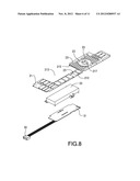
[0017] FIG. 8 is an exploded solid diagram of a first circuit board, a display module and a second circuit board in the touch panel of FIG. 1;
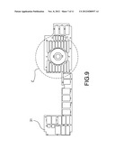
[0018] FIG. 9 is a top view of the first circuit board of FIG. 8;
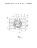
[0019] FIG. 10 is a drawing of partial enlargement of Area C in FIG. 9, wherein the area of touch sensors is in perspective to show the physical distribution state of each sensor;
[0020] FIG. 11 is a frame diagram of a touch control circuit in the touch panel of FIG. 1;
[0021] FIG. 12 is a flow chart of the touch control circuit of FIG. 11; and
[0022] FIG. 13 is a flow chart of a light-emitting device control circuit in the touch control circuit of FIG. 11.
DESCRIPTION OF THE PREFERRED EMBODIMENTS
[0023] While the Present Disclosure may be susceptible to embodiment in different forms, there is shown in the Figures, and will be described herein in detail, specific embodiments, with the understanding that the disclosure is to be considered an exemplification of the principles of the Present Disclosure, and is not intended to limit the Present Disclosure to that as illustrated.
[0024] As such, references to a feature or aspect are intended to describe a feature or aspect of an example of the Present Disclosure, not to imply that every embodiment thereof must have the described feature or aspect. Furthermore, it should be noted that the description illustrates a number of features. While certain features have been combined together to illustrate potential system designs, those features may also be used in other combinations not expressly disclosed. Thus, the depicted combinations are not intended to be limiting, unless otherwise noted.
[0025] In the embodiments illustrated in the Figures, representations of directions such as up, down, left, right, front and rear, used for explaining the structure and movement of the various elements of the Present Disclosure, are not absolute, but relative. These representations are appropriate when the elements are in the position shown in the Figures. If the description of the position of the elements changes, however, these representations are to be changed accordingly.
[0026] As shown in FIG. 1 to FIG. 8, the touch panel in the Present Disclosure comprises a main panel 1, a light-emitting touch module 2 arranged below the main panel 1, and a power switch 4 arranged on the main panel 1. There are mainly two different types of touch display modes on the touch panel, the first type of which is an integral combination of traditional touch and display, and the second type corresponds to novel combination touch area and combination display area according to the Present Disclosure.
[0027] The main panel 1 is a transparent ABS plastic member, it is a whole frame structure with only one opening at the lower end, and it has a base part 11 and lateral plates 12 extending downward from the surround of the base part 11. The light-emitting touch module 2 is received in a cavity that is formed by the base part 11 and the four lateral plates 12. The base part 11 is provided with a hole only at one corner to mount the power switch 4, when the touch panel is mount onto the washing machine, it just needs to have essential processing to the hole to achieve water-proof and dust-proof effect, in order to prevent the light-emitting touch module 2 from being damaged.
[0028] The base part 11 is provided with a plurality of first touch display areas 111 corresponding to the first type of touch mode, a display window 112 and one second touch display area 113 corresponding to the second type of touch mode.
[0029] The second touch display area 113 mainly comprises an annular combination touch area 114 and a combination display area 115 corresponding to the combination touch area 114, the combination display area 115 comprises a plurality of sub display units 118 arranged on left and right sides of the combination touch area 114, each sub display unit 118 is printed with a corresponding function display pattern design (not shown in the drawings, it may be respectively corresponding to one washing mode of the washing machine). The second touch display area 113 further comprises a touch display area 116 for executing functions in the center of the annular combination touch area 114.
[0030] A layer of non-transparent ink is printed at a part requiring no light transmission on the lower surface of the base part 11; at a part requiring light transmission, for example: at the back of the display pattern designs formed of characters and/or patterns within the first touch display area 111 and the sub display units 118 in the combination display area 115, a layer of transparent ink is printed, so that the effect of a transparent window is achieved, in a case that there is no light, the display pattern design is black, in a case that light is irradiated from the back of the transparent window, the corresponding display pattern designs can be seen.
[0031] The light-emitting touch module 2 comprises a first circuit board 21, a plurality of light-guiding members 22, a plurality of reflective members 23, a spacer 24, a main circuit module 3 and a touch control circuit 25 mounted on the main circuit module 3. With reference to FIG. 4 to FIG. 8, a first touch sensor 211 and a first light-emitting device 212 are correspondingly arranged on the top surface of the first circuit board 21 below the first touch display area 111 of the main panel 1. A notch 213 is also formed on one side of the first circuit board 21.
[0032] With reference to FIG. 9 and FIG. 10, on the top surface of the first circuit board 21 facing to the main panel 1, a plurality of second touch sensors 214 corresponding to the combination touch area 114 of the main panel 1, a third touch sensor 216 corresponding to the touch display area 116 for executing functions, a plurality of second light-emitting devices 215 corresponding to the sub display units 118 of the combination display area 115, and two third light-emitting devices 217 corresponding to the combination touch area 114 and the touch display area 116 for executing functions are arranged.
[0033] The first touch sensor 211, the second touch sensors 214 and the third touch sensor 216 in the embodiment are all capacitance-sensitive touch sensors, while in other embodiments, resistance-sensitive touch sensors also may be possible, these touch sensors 211, 214 and 216 may be used for sensing a proximity signal (for example, touch of the finger) of the operator. Wherein, below the first touch display area 111 and the touch display area 116 for executing functions, only one touch sensor is one-to-one arranged; while below the annular combination touch area 114 (with reference to FIG. 10), a plurality of second touch sensors 214 are continuously arrayed on the front surface of the first circuit board 21 along the annular rotation direction in such a manner that touch sensors are joined end to end; there are total eight second touch sensors 214, the boundary between two adjacent one of the second touch sensors 214 is dovetail-shaped, such boundary structure helps to reduce the signal interference between two adjacent second touch sensors 214; each one of the second touch sensors 214 is electrically and logically formed of copper foils (not shown) between two boundaries. The first light-emitting device 212, the second light-emitting devices 215 and the third light-emitting devices 217 are light-emitting diodes (LED), preferably.
[0034] The light-guiding members 22 are made of polycarbonate (PC) plastic and correspondingly arranged below each first touch display area 111, combination touch area 114, combination display area 115 and touch display area 116 for executing functions of the main panel 1. Wherein, the top surface of the light-guiding members 22 is preferably a rough fog surface that helps to achieve the effect of evenly projecting light upward; while the bottom surface thereof is preferably a smooth surface that helps to reduce escape of light from the bottom surface through full reflection in order to decrease attenuation. The lateral edge of the light-guiding members 22 is attached with the first light-emitting device 212, the second light-emitting devices 215 or the third light-emitting devices 217, thus to be able to guide light from the first light-emitting device 212, the second light-emitting devices 215 or the third light-emitting devices 217 into a certain area range in parallel, and then evenly project light upward through the fog surface on the top part onto the first touch display area 111, combination touch area 114, combination display area 115 or touch display area 116 for executing functions of the main panel 1, in order to display the function display pattern designs on the main panel 1.
[0035] The reflective members 23 are correspondingly arranged below the light-guiding members 22, and they may reflect light scattered from the bottom surface of the light-guiding members 22 onto the top surface of the light-guiding members 22 again to increase the brightness of the display pattern designs. With reference to FIG. 6, the reflective members 23 are preferably formed of a layer of reflective membrane printed on the first circuit board 21 with reflective ink (for example, white ink), and directly attached below the bottom surface of the light-guiding members 22, wherein the reflective members 23 in the first touch display area 111 and the touch display area 116 are directly printed above the first touch sensor 211 or the third touch sensor 216. Such reflective membrane has advantages of low cost and thin and light structure with respect to common reflective structures. By arranging reflective members 23 below the light-guiding members 22 for reflection, the light-emitting efficiency of the first light-emitting device 212, the second light-emitting devices 215 and the third light-emitting devices 217 may be improved, so that the brightness of the first touch display area 111, combination touch area 114, combination display area 115 or touch display area 116 for executing functions is increased, energy-saving and environmental protection are achieved.
[0036] The spacer 24 is arranged between the base part 11 of the main panel 1 and the first circuit board 21 and made of light tight materials (for example, black foam). Both surfaces of the spacer 24 are provided with glue, the top surface of the spacer is adhered with the lower surface of the main panel 1, and the bottom surface of the spacer is adhered with the upper surface of the first circuit board 21. For the light-guiding members 22, the spacer 24 may play roles of blocking light and positioning, in order to effectively prevent light interference and light leakage between different display areas. The spacer 24 is correspondingly provided with a plurality of bottom-to-top receiving holes 241 to correspondingly receive the light-guiding members 22, and the first light-emitting device 212, the second light-emitting devices 215 or the third light-emitting devices 217 inside.
[0037] With reference to FIG. 11, the touch control circuit 25 mainly comprises a microprocessor control circuit 251 and a light-emitting device control circuit 252. The microprocessor control circuit 251 consists of a power circuit, a microprocessor and an accessory circuit of the microprocessor, the microprocessor may be preferably a single chip machine CY8C22545. The light-emitting device control circuit 252 further consists of a shift register, a light-emitting device driving chip and other electronic elements, the model of the shift register may be preferably 74HC595D, and the model of the light-emitting device driving chip may be preferably DS2003CMX.
[0038] With reference to FIG. 12 and FIG. 13 together, the microprocessor control circuit 251 may monitor the sensed signal (in the embodiment, it corresponds the capacitance value of the touch sensors) of each one of the first touch sensor 211, the second touch sensors 214 and the third touch sensor 216 in real time, compare the sensed signal with a set threshold to judge the ON/OFF state of the function key corresponding to each touch sensor, and send the ON/OFF state signal to an external interface to drive the washing machine to do corresponding operations. In addition, the microprocessor control circuit 251 also may receive an LED display state control signal from the external interface, convert the signal into a driving signal, and send the driving signal to the light-emitting device control circuit 252. The light-emitting device control circuit 252 receives the signal sent by the microprocessor control circuit 251, and accurately drives each corresponding light-emitting device to enter different light-emitting states according to the signal logic: full-bright, half-bright, extinguished, in order to display different working states on the main panel 1.
[0039] During practical application, when the finger of the operator starts to approach one of the first touch display areas 111 from above, the sensed signal (in the embodiment, it corresponds to the capacitance value of the touch sensor) of the first touch sensor 211 below this first touch display area 111 will gradually increase and the sensed signal will be sent to the touch control circuit 25, when the touch control circuit 25 monitors that the capacitance value of the first touch sensor 211 exceeds the set threshold (at this moment, the finger has already touched or is quite close to the surface of this first touch display area 111), the touch control circuit 25 may correspondingly control the first light-emitting device 212 on the lateral edge of the first touch sensor 211 to change to the full-bright light-emitting state from the initial half-bright light-emitting state, in order to change the backlight state of the function display pattern designs on the first touch display area 111 of the main panel 1, and simultaneously, notify the washing machine with the operation information to do corresponding operations.
[0040] It should be particularly noted that, in the preferred embodiment, when the finger of the operator moves to a certain area in the combination touch area 114, the capacitance values of the several second touch sensors 214 in the areas close to the finger will change and the sensed signals are sent to the touch control circuit 25, the touch control circuit 25 then adds up these sensed signals and calculates the adjacent combinations with the most intense change of sensed signals through sensitive detection algorithm to judge the touch position of the finger is above which second touch sensor 214, in the preferred embodiment, the touch control circuit 25 also may further specifically judge whether the touch position is above the border part or the middle part of the second touch sensor 214, and then control the second light-emitting device 215 below the sub display unit 118 corresponding to the touch position within the combination display area 115 to change to the selected second light-emitting state (in the embodiment, it corresponds to full-bright light-emitting state) from the initial non-selected first light-emitting state (in the embodiment, it corresponds to half-bright light-emitting state), while still keep the second light-emitting devices 215 below other non-selected sub display units 118 in half-bright light-emitting state; through such design, each one of the physical second touch sensors 214 may correspond to two corresponding sub display units 118 (each one of the sub display units 118 corresponds to one specific washing mode) in the combination display area 115, therefore eight second touch sensors 214 in the combination touch area 114 may correspond to sixteen sub display units 118 in the combination display area 115, so that the distribution density of second touch sensors 214 may be decreased to reduce the manufacturing difficulty and the manufacturing cost. Of course, other sensitive detection algorithms may be employed, so that the second touch sensors 214 establish different mapping relations with the sub display units 118, for example: the initial value may be any one sub display unit 118 displaying in full-bright light-emitting, when the finger slips through one second touch sensor 214 each time, the next adjacent sub display unit 118 is automatically switched to display in full-bright light-emitting, while the last sub display unit 118 recoveries to display in half-bright state. In this way, when the finger of the operator rotates and moves along the combination touch area 114, the second light-emitting devices 215 of the corresponding selected sub display units 118 in the combination display area 115 will display in full-bright in turn, while the second light-emitting devices 215 of the non-selected sub display units 118 will recovery to the primary half-bright state, such operating interface enables the operator to be able to switch and select among many different washing modes conveniently. Finally, after the finger of the operator falls in the touch display area 116 for executing functions, the third touch sensor 216 may sense the proximity signal of the finger of the operator and send the sensed signal to the touch control circuit 25 to control the full-bright light-emitting display of the third light-emitting devices 217, at the same time, the washing machine may start to wash according to the selected washing mode, such cool operating interface is fairly flexible, it helps to provide better user experience thus to improve the grade of electrical appliances, and the operation is also quite convenient and fast.
[0041] The main circuit module 3 comprises a second circuit board 31, a cable connector 32 and a display module 33.
[0042] The second circuit board 31 is arranged below the notch 213 of the first circuit board 21 and forms a height difference with the first circuit board 21 in order to have an interval of distance in space, and the second circuit board 31 may be electrically connected with the first circuit board 21 through a connector (not shown). In the preferred embodiment, the touch control circuit 25 is preferably arranged on the second circuit board 31. Through the separated arrangement of the two circuit boards 21 and 31, the first touch sensor 211, the second touch sensors 214 and the third touch sensor 216 may be separated from the touch control circuit 25 in space, so that the interference for the first touch sensor 211, the second touch sensors 214 and the third touch sensor 216 on the first circuit board 21 from the electromagnetic radiation emitted by the touch control circuit 25 and other power elements on the second circuit board 31 may be reduced, therefore the event that wrong sensed signals are sent due to the fluctuation of the capacitance value of touch sensors to further cause the touch control circuit 25 to have erroneous judgment operations is prevented.
[0043] One end of the cable connector 32 may be directly welded on the second circuit board 31, and the other end thereof may be adapted with other circuits in the washing machine, for example, connected with a motor control panel in the washing machine, to send the related operation signals captured by the touch control circuit 25 to the main control circuit of the washing machine to control the running of the motor.
[0044] The display module 33 is arranged correspondingly below the display window 112 on the base part 11 of the main panel 1. The display module 33 may be an LED light-emitting module and also may be an LCD light-emitting module, and it provides indicators of the working state of the washing machine by displaying various different light-emitting patterns. The display module 33 is arranged at the notch 213 on one side of the first circuit board 21 in parallel. Preferably, the second circuit board 31 is directly welded on the bottom surface of the display module 33, while the electronic elements forming the touch control circuit 25 are arranged on the bottom surface of the second circuit board 31 deviating from the main panel 1, the touch control circuit 25 on the second circuit board 31 and the touch sensors on the first circuit board 21 are designed into a deviated structure, so that the interference to the touch sensors from the touch control circuit 25 also may be reduced. On the other hand, the combined application of the display module 33 with high display density and the light-emitting touch module 2 with touch function but low display density together helps to improve the key arrangement of the touch panel and reduce the cost.
[0045] Compared with the prior art, according to the touch panel in the Present Disclosure, the combination touch area 114 is arranged on the main panel 1, the corresponding combination display area 115 is arranged around the combination touch area 114, the combination display area 115 comprises a plurality of sub display units 118; simultaneously, a plurality of continuously arrayed touch sensors 214 are correspondingly arranged below the combination touch area 114, and light-emitting devices 215 are correspondingly arranged below the sub display units 118 in the combination display area 115; in this way, the operator may correspondingly select the sub display units 118 in the combination display area 115 in a manner of rotating and moving with a finger in the combination touch area 114, so that a more humane operating interface is obtained, such operating interface has a sense of technology, it helps to obtain better user experience, thus to improve the grade of electromechanical products, and the operation is also quite convenient and fast.
[0046] While a preferred embodiment of the Present Disclosure is shown and described, it is envisioned that those skilled in the art may devise various modifications without departing from the spirit and scope of the foregoing Description and the appended Claims.
User Contributions:
Comment about this patent or add new information about this topic:
| People who visited this patent also read: | |
| Patent application number | Title |
|---|---|
| 20120282061 | FASTENER |
| 20120282060 | LOOSE RESISTANT NUT FASTENER |
| 20120282059 | ADHESIVE PACKAGE AND USE THEREOF WITH AN ANCHORING ELEMENT |
| 20120282058 | Anchor Rod |
| 20120282057 | LASHING STRAP HOOK LOAD SECURING SYSTEM |
Images included with this patent application:
 |  |
 |  |
 |  |
 |  |
 |  |
 |  |
| New patent applications in this class: | |
| Date | Title |
|---|---|
| 2022-05-05 | System and method for detecting and characterizing touch inputs at a human-computer interface |
| 2022-05-05 | Touchscreen calibration circuit |
| 2022-05-05 | Touch panel and touch panel operation method thereof |
| 2022-05-05 | Electronic device including a sensor layer |
| 2022-05-05 | Touch panel, touch screen and display device |
| New patent applications from these inventors: | |
| Date | Title |
|---|---|
| 2022-03-10 | Electronic device |
| 2013-05-16 | Touch panel |
| Top Inventors for class "Computer graphics processing and selective visual display systems" | |
| Rank | Inventor's name |
|---|---|
| 1 | Katsuhide Uchino |
| 2 | Junichi Yamashita |
| 3 | Tetsuro Yamamoto |
| 4 | Shunpei Yamazaki |
| 5 | Hajime Kimura |