Patent application title: ROCKER ARM ASSEMBLY FOR INTERNAL COMBUSTION ENGINE
Inventors:
Gary J. Arvan (Rochester Hills, MI, US)
Assignees:
GM GLOBAL TECHNOLOGY OPERATIONS LLC
IPC8 Class: AF01L118FI
USPC Class:
123 9039
Class name: Internal-combustion engines poppet valve operating mechanism rocker
Publication date: 2012-10-25
Patent application number: 20120266836
Abstract:
An internal combustion engine comprising valve sets through which
combustion air enters a cylinder is mixed with fuel for combustion
therein and through which products of combustion exit. A valve train
assembly comprises a drive rocker arm, including a first, proximal end in
contact with a rotatable camshaft and a second, distal end in contact
with a valve shaft of a first valve of a valve set and a driven rocker
arm including a first, proximal end in contact with the drive rocker arm
at a location that is adjacent to the first, proximal end thereof and a
second, distal end in contact with a valve shaft of a second valve of a
valve set. The drive rocker arm and the driven rocker arm operate to move
the valves reciprocally from a closed to an open position.Claims:
1. An internal combustion engine comprising: a cylinder having a piston
disposed for reciprocation therein; valve sets through which combustion
air enters the cylinders is mixed with fuel for combustion therein and
through which products of combustion exit the cylinder; a valve train
assembly, configured to assure the proper opening and closing of the
valve sets and comprising: a drive rocker arm, including a first,
proximal end in contact with a rotatable camshaft and a second, distal
end in contact with a valve shaft of a first valve of a valve set; and a
driven rocker arm including a first, proximal end in contact with the
drive rocker arm at a location that is adjacent to the first, proximal
end thereof and a second, distal end in contact with a valve shaft of a
second valve of a valve set, the drive rocker arm and the driven rocker
arm operable to move the valves reciprocally from a closed to an open
position.
2. The internal combustion engine of claim 1, further comprising a push rod extending between the first, proximal end of the drive rocker arm and the rotatable camshaft.
3. The internal combustion engine of claim 1, wherein the drive rocker arm and the driven rocker arm are individual components with the driven rocker arm actuated by the drive rocker arm.
4. The internal combustion engine of claim 1 wherein the drive rocker arm is mounted on a rocker shaft for rotation about the axis thereof and operates, through rotation about the rocker shaft axis, to move a valve.
5. The internal combustion engine of claim 1 wherein the driven rocker arm is mounted on a rocker shaft for rotation about the axis thereof and operates, through rotation about the rocker shaft axis, to move a valve.
6. A valve train assembly for an internal combustion engine comprising: a drive rocker arm, including a first, proximal end in contact with a rotatable camshaft and a second, distal end in contact with a valve shaft of a first valve of a valve set; and a driven rocker arm including a first, proximal end in contact with the drive rocker arm at a location that is adjacent to the first, proximal end thereof and a second, distal end in contact with a valve shaft of a second valve of a valve set, the drive rocker arm and the driven rocker arm operable to move the valves reciprocally from a closed to an open position, wherein the a valve train assembly is configured to assure the simultaneous opening and closing of the valve sets.
7. The valve train assembly of claim 6, wherein the drive rocker arm and the driven rocker arm are individual components with the driven rocker arm actuated by the drive rocker arm.
8. The valve train assembly of claim 6, wherein the drive rocker arm is mounted on a rocker shaft for rotation about the axis thereof and operates, through rotation about the rocker shaft axis, to move a valve.
9. The internal combustion engine of claim 1, wherein the drive rocker arm and the driven rocker arm comprise a single component.
10. The valve train assembly of claim 6, wherein the drive rocker arm and the driven rocker arm comprise a single component.
Description:
CROSS-REFERENCES TO RELATED APPLICATIONS
[0001] This patent application claims priority to U.S. Patent Application Ser. No. 61/478,645 filed Apr. 25, 2011 which is hereby incorporated herein by reference in its entirety.
FIELD OF THE INVENTION
[0002] Exemplary embodiments of the invention relate to valve train assemblies for internal combustion engines and, more particularly, to a rocker arm configuration therefore.
BACKGROUND
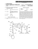
[0003] With reference to FIGS. 1 and 4, the actuation of intake and exhaust valves 12 and 14 respectively, in a 4-valve per cylinder internal combustion engine 10, particularly a diesel engine, may require the use of a valve bridge 16 due to various design constraints such as actuation type, valve location, cylinder and/or cylinder head configuration, fuel injector location, or a combination thereof. A valve bridge 16 is a device that spans the distance between and contacts two valves, either intake or exhaust, any has a contact point roughly equidistant from the centerline of both valves. The valve bridge 16 is used as a location for actuation of the valve set by a rocker arm 18.
[0004] A common issue with a valve bridge system of the type just described is that various tolerances and operating parameters such as valve length, valve seat configuration, valve spring height and rate or a combination thereof may result in one valve opening and/or closing at a different time than the other valve in a set. As a result, the profile of the cam actuator must be designed with longer and higher ramps to avoid high contact velocities between the valves 12, 14 and their respective valve seats. Such long ramps compromise engine breathing, resulting in reduced power, reduced torque and increased emissions.
SUMMARY
[0005] An internal combustion engine comprising a cylinder having a piston disposed for reciprocation therein, valve sets through which combustion air enters the cylinder is mixed with fuel for combustion therein and through which products of combustion exit the cylinder and a valve train assembly, configured to assure the proper opening and closing of the valve sets. The valve train assembly comprises a drive rocker arm, including a first, proximal end in contact with a rotatable camshaft and a second, distal end in contact with a valve shaft of a first valve of a valve set and a driven rocker arm including a first, proximal end in contact with the drive rocker arm at a location that is adjacent to the first, proximal end thereof and a second, distal end in contact with a valve shaft of a second valve of a valve set. The drive rocker arm and the driven rocker arm operate to move the valves reciprocally from a closed to an open position along a valve shaft axis of each valve.
BRIEF DESCRIPTION OF THE DRAWINGS
[0006] Other objects, features, advantages and details appear, by way of example only, in the following detailed description of the embodiments, the detailed description referring to the drawing in which:
[0007] FIG. 1 is a partial schematic view of an internal combustion engine having a valve train assembly utilizing a known valve bridge system;
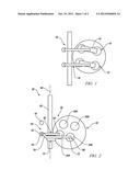
[0008] FIG. 2 is a partial schematic plan view of an internal combustion engine having a valve train assembly embodying features of the invention;
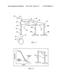
[0009] FIG. 3 is a partial schematic side view of the internal combustion engine of FIG. 2 embodying features of the invention; and
[0010] FIG. 4 illustrates additional detail of the internal combustion engine of FIG. 1.
DESCRIPTION OF THE EMBODIMENTS
[0011] The following description is merely exemplary in nature and is not intended to limit the present disclosure, its application or uses. It should be understood that throughout the drawings, corresponding reference numerals indicate like or corresponding parts and features.
[0012] Referring to FIGS. 2 and 3, an internal combustion engine 30 includes one or more cylinders 32 that receive a piston (not shown) for reciprocation therein. Combustion air enters the cylinders 32 through intake valve sets 34 (first intake valve 34A and second intake valve 34B) and is mixed with fuel for combustion therein. The products of combustion exit the cylinders 32 through exhaust valve sets 36 (first exhaust valve 36A and second exhaust valve 36B), and the cycle is repeated.
[0013] Regulation of the intake and exhaust valve sets 34, 36 is through a valve train assembly 38 that is configured to assure the proper opening and closing of the valves including speed, lift and timing. In an exemplary embodiment, the valve train assembly 38 may comprise one or more rotatable camshafts 40 having eccentric cams 42 disposed thereon. In the embodiment illustrated, a push rod 44 has a first end 46 in communication with the surface of the cam 42 and a second end 48 in communication with a first, proximal end 52 of a rocker arm assembly 50 thereby connecting the cam with the rocker arm assembly. A hydraulic element 54 may be disposed between the push rod 44 and the cam 42 or the rocker arm assembly 50 and accounts for any misadjustment or wear ("valve lash") between the various components during operation of the internal combustion engine 10.
[0014] In an exemplary embodiment, the rocker arm assembly 50 includes a drive rocker arm 56, including the first, proximal end 52 in contact with the push rod 44 that is mounted on a rocker shaft 58 for rotation about the axis 60 thereof. A second, distal end 62 of the drive rocker arm 56 is in contact with the valve shaft 64A of the intake valve 34A and operates, through rotation about the rocker shaft axis 60 to move the valve reciprocally from a closed to an open position along the valve shaft axis. A driven rocker arm 68 includes a first, proximal end 70 that is in contact with the drive rocker arm 56 at a location that is adjacent to the first, proximal end 52 thereof. The driven rocker arm 68 may also be mounted on rocker shaft 58 for rotation about the axis 60 thereof. A second, distal end 72 of the driven rocker arm 68 is in contact with the valve shaft of the intake valve 34B and operates, through rotation about the rocker shaft axis 60 to move the valve reciprocally from a closed to an open position along the valve shaft axis. In exemplary embodiments, the drive rocker arm 56 and the driven rocker arm 68 may be individual components with the driven rocker arm actuated by the drive rocker arm as illustrated in FIG. 3. Optionally, the drive rocker arm and the driven rocker arm may be fixed together or constructed as a single component to form the rocker arm assembly 50. A hydraulic element may be located between the drive and the driven rocker arms 56 and 68 to account for any lash between the two components during operation of the internal combustion engine 30. In an exemplary embodiment, if the drive rocker arm 56 and the driven rocker arm 68 are both mounted to the rocker shaft 58, a non-concentric bushing 74 (FIG. 2.) may be used at either the drive or the driven pivot to adjust the rocker arm assembly 50 to the desired valve lift ratios (shorter, optimized ramp as illustrated in FIG. 4). It is contemplated that the rocker shaft 58 may be dispensed with and the drive rocker arm 56 and the driven rocker arm 68 may be pivotally mounted on individual pedestal mounts (not shown). In either configuration the rocker arm assembly 50 may be configured to provide either equal or different openings for each valve 34A & 34B, however opening and closing of the valves will occur simultaneously. For descriptive simplicity, the valve train assembly 38 embodying the invention has been illustrated and described with respect to intake valves 34; however the valve train assembly has equal application to the operation of exhaust valves 36 without varying from the scope of the invention. Additionally, while the valve train assembly 38 embodying the invention has been illustrated and described with respect to its operation in an internal combustion engine having push rods 44 for valve actuation, it is contemplated that the invention has equal application to an overhead cam to rocker arm valve train assembly without deviating from the scope of the invention.
[0015] While the invention has been described with reference to exemplary embodiments, it will be understood by those skilled in the art that various changes may be made and equivalents may be substituted for elements thereof without departing from the scope of the invention. In addition, many modifications may be made to adapt a particular situation or material to the teachings of the invention without departing from the essential scope thereof. Therefore, it is intended that the invention not be limited to the particular embodiments disclosed for carrying out this invention, but that the invention will include all embodiments falling within the scope of the application.
User Contributions:
Comment about this patent or add new information about this topic:
Images included with this patent application:
 |  |
 |
| Similar patent applications: | |
| Date | Title |
|---|---|
| 2010-07-22 | Rocker arm for internal combustion engine |
| 2010-12-16 | Intake system for internal combustion engine |
| 2011-01-27 | Control system for internal combustion engine |
| 2012-06-14 | Laser spark plug for an internal combustion engine |
| 2012-07-19 | Intake system for internal combustion engine |
| New patent applications in this class: | |
| Date | Title |
|---|---|
| 2018-01-25 | Valve lift control device |
| 2016-06-30 | Sliding member and method of manufacturing the same |
| 2016-06-16 | Reciprocating piston internal combustion engine including a sensor system on a gas exchange valve |
| 2016-05-19 | Method of remanufacturing a rocker arm and a remanufactured rocker arm |
| 2016-03-10 | Method of remanufacturing a rocker arm and remanufactured rocker arm |
| New patent applications from these inventors: | |
| Date | Title |
|---|---|
| 2011-07-14 | Engine exhaust system and method of operation |
| 2011-04-21 | Turbocharger and air induction system incorporating the same and method of using the same |
| 2010-03-25 | Resonator and crankcase ventilation system for internal combustion engine |
| 2010-03-25 | Valvetrain control strategies for exhaust aftertreatment devices |
| 2009-02-19 | Piston squirter system and method |
| Top Inventors for class "Internal-combustion engines" | |
| Rank | Inventor's name |
|---|---|
| 1 | Ross Dykstra Pursifull |
| 2 | Gopichandra Surnilla |
| 3 | Joseph Norman Ulrey |
| 4 | Thomas G. Leone |
| 5 | Chris Paul Glugla |