Patent application title: Indicating Quality of GNSS Position Fixes
Inventors:
Ulrich Vollath (Superior, CO, US)
Ulrich Vollath (Superior, CO, US)
Sidharth Nair (Phoenix, AZ, US)
Jesus Michael Martinez (Broomfield, CO, US)
Greg Price (Nelson, NZ)
Glenn Waterland (Westminster, CO, US)
Mark Gibson (Portland, OR, US)
Assignees:
Trimble Navigation Limited
IPC8 Class:
USPC Class:
34235725
Class name: Determining a navigation solution using signals transmitted by a satellite radio beacon positioning system satellite radio beacon positioning system transmitting time-stamped messages; e.g., gps [global positioning system], glonass [global orbiting navigation satellite system] or galileo (ipc) determining position (ipc)
Publication date: 2012-09-13
Patent application number: 20120229332
Abstract:
Methods and apparatus are provided for reporting quality of GNSS position
fixes. A desired quality mode selection is obtained. Position fixes with
respective precision estimates and satellite tracking information are
obtained. For each of a plurality of position fixes a current positioning
quality is determined, based on the precision estimates and satellite
tracking information and quality mode selection. Current positioning
quality is reported. The quality selection can be a preference of
availability over accuracy, or accuracy over availability, or a balance
of availability and accuracy.Claims:
1. A method of reporting quality of GNSS position fixes, comprising:
obtaining a desired quality mode selection, obtaining position fixes with
respective precision estimates and satellite tracking information,
determining for each of a plurality of position fixes a current
positioning quality based on the precision estimates and satellite
tracking information and quality mode selection, and reporting current
positioning quality.
2. The method of claim 1, wherein the quality selection comprises a preference of availability over accuracy, or accuracy over availability, or a balance of availability and accuracy.
3. The method of claim 2, wherein obtaining position fixes comprises processing GNSS receiver data subject to at least one control favoring the preference.
4. The method of claim 3, wherein the at least one control favoring the preference comprises at least one of: a satellite elevation mask, a C/No (Carrier-to-Noise power ratio) mask, a DOP (Dilution of Precision) mask, a control providing additional accuracy, and a control providing additional availability.
5. The method of claim 1, wherein the precision estimate for each position fix is determined from covariances of parameters estimated with the position fix.
6. The method of claim 1, wherein determining the positioning quality comprises at least one of: determining whether satellites are being tracked, determining whether a position fix is being determined, determining whether availability exceeds a threshold, determining whether availability and accuracy are balanced, and determining whether accuracy exceeds a threshold.
7. The method of claim 1, wherein reporting current positioning quality comprises displaying at least one of: an icon indicating current positioning quality, a color indicating current positioning quality, a number of bars indicating whether criteria corresponding to the desired quality mode selection are satisfied
8. The method of claim 7, wherein reporting current positioning quality comprises displaying an indication of the desired quality mode selection.
9. An article of manufacture comprising a computer-readable storage device embodying instructions which enable a processor to perform the method according to claim 1.
10. Apparatus for reporting quality of GNSS position fixes, comprising: a memory storing a desired quality mode selection, a memory storing position fixes with respective precision estimates and satellite tracking information, a processing element to determine for each of a plurality of position fixes a current positioning quality based on the precision estimates and satellite tracking information and quality mode selection, and a reporting element to report current positioning quality.
11. The apparatus of claim 10, wherein the quality selection comprises a preference of availability over accuracy, or accuracy over availability, or a balance of availability and accuracy.
12. The apparatus of claim 11, wherein the position fixes are determined from processing of GNSS receiver data subject to at least one control favoring the preference.
13. The apparatus of claim 12, wherein the at least one control favoring the preference comprises at least one of: a satellite elevation mask, a C/No (Carrier-to-Noise power ratio) mask, a DOP (Dilution of Precision) mask, a control providing additional accuracy, and a control providing additional availability.
14. The apparatus of claim 13, wherein the precision estimate for each position fix is determined from covariances of parameters estimated with the position fix.
15. The apparatus of claim 10, wherein the processing element determines the positioning quality based on at least one of: whether satellites are being tracked, whether a position fix is being determined, whether availability exceeds a threshold, whether availability and accuracy are balanced, and whether accuracy exceeds a threshold.
16. The apparatus of claim 10, wherein the reporting element displays at least one of: an icon indicating current positioning quality, a color indicating current positioning quality, a number of bars indicating whether criteria corresponding to the desired quality mode selection are satisfied.
17. The apparatus of claim 16, wherein the reporting element displays an indication of the desired quality mode selection.
Description:
RELATED APPLICATIONS
[0001] The following are related hereto and incorporated herein in their entirety by this reference: U.S. Provisional Application for Patent No. 61/277,184 filed 19 Sep. 2009 (TNL A-2585P); International Patent Application PCT/US2009/059552 filed 5 Oct. 2009 (TNL A-2288PCT); U.S. Provisional Application for Patent No. 61/195,276 filed 6 Oct. 2008 (TNL A-2288P); International Patent Application PCT/US/2009/004471 filed 5 Aug. 2009 (TNL A-2526PCT); International Patent Application PCT/US/2009/004473 filed 5 Aug. 2009 (TNL A-2525PCT); International Patent Application PCT/US/2009/004474 filed 5 Aug. 2009 (TNL A-2524PCT); International Patent Application PCT/US/2009/004472 filed 5 Aug. 2009 (TNL A-2523PCT); International Patent Application PCT/US/2009/004476 filed 5 Aug. 2009 (TNL A-2339PCT); U.S. Provisional Application for Patent No. 61/189,382 filed 19 Aug. 2008 (TNL A-2339P); U.S. patent application Ser. No. 12/224,451 filed 26 Aug. 2008, United States Patent Application Publication U.S. 2009/0027625 A1 (TNL A-1789US); International Patent Application PCT/US07/05874 filed 7 Mar. 2007, International Publication No. WO 2008/008099 A2 (TNL A-1789PCT); U.S. patent application Ser. No. 11/988,763 filed 14 Jan. 2008, United States Patent Application Publication U.S. 2009/0224969 A1 (TNL A-1743US); International Patent Application No. PCT/US/2006/034433 filed 5 Sep. 2006, International Publication No. WO 2007/032947 Al (TNL A-1743PCT); U.S. Pat. No. 7,432,853 granted 7 Oct. 2008; (TNL A-1403US); (TNL A-1403PCT); International Patent Application No. PCT/US2004/035263 filed 22 Oct. 2004 and International Publication Number WO 2005/045463 A1 (TNL A-1403PCT); U.S. Pat. No. 6,862,526 granted 1 Mar. 2005 (TNL A-1006US); U.S. Provisional Application for Patent No. 61/396,676, filed 30 May 2010 (TNL A-2751P); U.S. Provisional Application for Patent No. 61/337,980 filed 14 Feb. 2010 (TNL A-2633P); International Application PCT US11/24733 filed 14 Feb. 2011 (TNL A-2633PCT); International Application PCT US11/24743 filed 14 Feb. 2011 (TNL A-2939PCT); and International Application PCT US11/24763 filed 14 Feb. 2011 (TNL A-2940PCT).
BACKGROUND
[0002] 1. Field of the Invention
[0003] The present invention relates to GNSS positioning, and particularly to indicating quality of GNSS position fixes.
[0004] 2. Prior Art
[0005] Lightbar guidance systems provide a visual display to assist an operator in guiding a vehicle, such as an agricultural machine, over a desired course. Examples of such systems include the EZ-Guide 250 and EZ-Guide 500 Lightbar Guidance Systems available commercially from Trimble Navigation Limited (Trimble). These can be combined with an automated steering system such as the Trimble EZ-Steer system.
[0006] The visual display includes a number of operational elements, indicating for example whether the vehicle is on or to the side of the intended path, swath lines, swath numbers, vehicle position and heading relative to the current swath, spray coverage, overlap, and/or a menu of possible user selections.
[0007] However, available systems offer limited ability to perform guided operations when GNSS satellite positioning quality is reduced.
[0008] Improved systems are desired which provide additional information and/or allow the user better control of the system.
SUMMARY
[0009] Methods and apparatus in accordance with some embodiments of the invention provide for user selection of a positioning quality mode, and for reporting of positioning quality based on the selected positioning quality mode. In accordance with some embodiments, the selection of positioning quality mode allows for vehicle operation at times of reduced GNSS satellite positioning quality.
BRIEF DESCRIPTION OF THE DRAWING
[0010] FIG. 1 shows an image of a positioning display in accordance with some embodiments of the invention;
[0011] FIG. 2 shows an example of positioning quality indicator characteristics in accordance with some embodiments of the invention;
[0012] FIG. 3 shows an example of positioning quality indicator logic in accordance with some embodiments of the invention;
[0013] FIG. 4 shows an example of threshold selection in accordance with some embodiments of the invention;
[0014] FIG. 5 shows an image of a positioning display with auto mode selection in accordance with some embodiments of the invention;
[0015] FIG. 6 shows an example of status indicators in accordance with some embodiments of the invention;
[0016] FIG. 7 shows an example of status indicator display icons in accordance with some embodiments of the invention;
[0017] FIG. 8 shows an image of a positioning display with status indicator in accordance with some embodiments of the invention;
[0018] FIG. 9 shows a covariance matrix transformation and precision determination in accordance with some embodiments of the invention;
[0019] FIG. 10 shows a process for evaluating positioning precisions in accordance with some embodiments of the invention;
[0020] FIG. 11 shows a process for evaluating positioning precisions in accordance with some embodiments of the invention; and
[0021] FIG. 12 is a block diagram of an integrated GNSS receiver system used in some embodiments of the invention.
DETAILED DESCRIPTION
[0022] Methods and apparatus in accordance with some embodiments of the invention provide for user selection of a positioning quality mode, and for reporting of positioning quality based on the selected positioning quality mode. In accordance with some embodiments, the selection of positioning quality mode allows for vehicle operation at times of reduced GNSS satellite positioning quality.
[0023] In accordance with some embodiments, a quality mode option enables a user to select between favoring accuracy, favoring availability, and balancing accuracy and availability.
[0024] In accordance with some embodiments, the quality mode selection controls one or more parameters affecting positioning accuracy and/or availability, such as satellite elevation masks, C/No (Carrier-to-Noise ratio) masks, DOP (Dilution of Precision) masks, and any other controls to provide additional accuracy or availability.
[0025] In accordance with some embodiments, the selection balance accuracy and availability is a default selection which can be changed by entry of an alternate selection.
[0026] In accordance with some embodiments, a status indicator reports which of the quality mode options is currently selected.
[0027] Some embodiments provide a positioning quality indicator. The user can select the desired level of GNSS positioning quality. This can enable extended operating hours by running the system when GNSS satellites are less available and possibly providing lower positioning quality. Alternatively, the user can select the best level of quality to achieve maximum positioning accuracy. Maximum positioning accuracy also depends on the type of GNSS correction data in use.
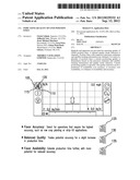
[0028] FIG. 1 shows a screen display 100 in accordance with some embodiments. An example of a quality indicator is shown at 105. Quality indicator 105 includes a bracket 110 indicating the selected positioning quality level, a set of signal bars 115 indicating GNSS signal quality, and an icon 120 indicating current positioning quality.
[0029] In this example, bracket 110 underscores one, two or three of the signal bars 115.
[0030] When the selected position quality favors accuracy, bracket 110 underscores one signal bar as shown at 125. Operations requiring highest accuracy are, for example, row crop planting or strip-till operation. The highest accuracy mode offers best pass-to-pass and year-to-year repeatability.
[0031] When the selected position quality favors a balance between accuracy and availability, bracket 110 underscores two signal bars as shown at 130. Selecting balanced quality trades potential accuracy for an increase in production time.
[0032] When the selected position quality favors availability, bracket 110 underscores three signal bars as shown at 135. Favoring availability extends production time further, with more potential for reduced accuracy. This option can sometimes trade some accuracy for more availability or runtime. This option may still achieve the highest level of accuracy for the correction data source in use. For example, when using this option with RTK corrections, the system may use positions that are greater than 1'' pass-to-pass accuracy.
[0033] The correction data source may be, for example, RTK, SBAS, Omnistar, StarFire, or any other suitable correction data source available now or in the future.
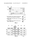
[0034] FIG. 2 shows a display scheme 200 for using quality indicator 105 to report position quality in accordance with some embodiments of the invention.
[0035] In this example, the configurations of quality indicator 105 are shown in upper row 205 for a position quality selection favoring availability, in middle row 210 for a position quality selection favoring a balance between availability and accuracy, and in lower row 215 for a position quality selection favoring accuracy.
[0036] FIG. 2 shows the configurations organized in columns from less accurate to more accurate according to various conditions: (1) no satellites tracked, (2) satellites tracked but no position of any type, (3) some position available but could be wrong source or does not meet the Favor Availability criteria, (4) Favor Availability criteria met, (5) Balanced Quality criteria met, and (6) Favor Accuracy criteria met.
[0037] The configuration of quality indicator 105 which is displayed at any given time is determined by which position quality has been selected by the user, and by the criteria which are currently satisfied.
[0038] The configurations when the Favor Availability position quality has been selected are in row 205. For condition (1), no quality indicator is provided. For condition (2), the quality indicator shows one signal bar in yellow and shows the satellite icon in yellow. For condition (3), the quality indicator shows two signal bars in yellow and shows the satellite icon in yellow. For condition (4), the quality indicator shows three signal bars in green and shows the satellite icon in green. For condition (5), the quality indicator shows four signal bars in green and shows the satellite icon in green. For condition (6), the quality indicator shows five signal bars in green and shows the satellite icon in green.
[0039] The configurations when Balanced position quality has been selected are in row 210. For condition (1), the quality indicator shows no signal bars and shows the satellite icon in red. For condition (2), the quality indicator shows one signal bar in yellow and shows the satellite icon in yellow. For condition (3), the quality indicator shows two signal bars in yellow and shows the satellite icon in yellow. For condition (4), the quality indicator shows three signal bars in yellow and shows the satellite icon in yellow. For condition (5), the quality indicator shows four signal bars in green and shows the satellite icon in green. For condition (6), the quality indicator shows five signal bars in green and shows the satellite icon in green.
[0040] The configurations when the Favor Accuracy position quality has been selected are in row 215. For condition (1), the quality indicator shows no signal bars and shows the satellite icon in red. For condition (2), the quality indicator shows one signal bar in yellow and shows the satellite icon in yellow. For condition (3), the quality indicator shows two signal bars in yellow and shows the satellite icon in yellow. For condition (4), the quality indicator shows three signal bars in yellow and shows the satellite icon in yellow. For condition (5), the quality indicator shows four signal bars in yellow and shows the satellite icon in yellow. For condition (6), the quality indicator shows five signal bars in green and shows the satellite icon in green.
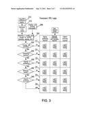
[0041] FIG. 3 shows an example of a display logic scheme 300 for controlling the quality indicator configurations of FIG. 2. A GNSS receiver (not shown) provides antenna position estimates and satellite tracking information 305 along with data 310 related to precision of the position estimates, such as covariances of parameters estimated with the position estimates.
[0042] The covariances are used to determine a measure of position quality 315 such as a horizontal position error estimate, a three-dimensional position error estimate, a vertical position error estimate, or other metric suitable to the application for which the position estimates are to be used.
[0043] A process flow 320 determines if position quality is adequate for the intended activity, such as planting or spraying as a series of decision elements. Decision element 325 determines whether satellites are tracked. If no, a quality indicator associated with condition (1) is displayed. If satellites are tracked, decision element 330 determines whether a position estimate is being generated. If no, a quality indicator associated with condition (2) is displayed.
[0044] If a position estimate is being generated, decision element 335 determines whether highest availability criteria are met. If no, a quality indicator associated with condition (3) is displayed. If highest availability criteria are met, decision element 340 determines whether balanced quality criteria are met. If no, a quality indicator associated with condition (4) is displayed.
[0045] If the balanced quality criteria are met, decision element 345 determines whether highest accuracy criteria are met. If no, a quality indicator associated with condition (5) is displayed. If the highest accuracy criteria are met, a quality indicator associated with condition (6) is displayed.
[0046] In each case, the quality indicator displayed depends on the quality mode selected by the user: highest availability, balanced availability and accuracy, or highest accuracy.
[0047] Many different graphical depictions can be used to display performance levels. Signal bars are compact and easily integrated with a red/yellow/green satellite depiction of go, warning, no-go conditions.
[0048] In accordance with some embodiments, the quality indicator display depends on the quality mode selected by the user, while the associated positioning precision depends on the correction data, if any, used in generating position estimates.
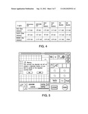
[0049] FIG. 4 shows an example in which the user can select between three quality levels (gold, silver, bronze), each level having an associated 2-sigma positioning accuracy for a given correction data type. The correction data types are, for example: autonomous positioning, differential GPS or virtual base station positioning, Omnistar XP absolute positioning, Omnistart HP absolute positioning, RTK absolute positioning, and Virtual Reference Station absolute positioning. Other correction data types can be used if desired.
[0050] In the example of FIG. 4, the user can engage autosteering for a selected accuracy mode. If the positioning quality falls below the criteria for the selected accuracy mode, the autosteering is disabled and the user is notified via a suitable display. The user can then await resumption of positioning quality of the selected accuracy mode, or can select a less demanding accuracy mode and continue operation under the less demanding accuracy mode.
[0051] For example, if the user selects Silver RTK, autosteering can be engaged within a +/-3 inch pass-to-pass accuracy. Operation may be better than one inch accuracy and so indicated, thus within the accuracy threshold. If positioning accuracy falls below the threshold associated with the selected positioning mode, the user is presented with an option to continue under a less accurate positioning mode, as in the example of FIG. 5.
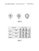
[0052] Positioning quality is reported in some embodiments with a status indicator which indicates a convergence level for a correction data type in use. FIG. 6 shows an example in which the status indicator represents three positioning accuracy modes: gold, silver, bronze.
[0053] FIG. 7 is a matrix showing the action taken to control the auto-steering system, depending on which of the positioning accuracy modes is selected by the user. When positioning accuracy is better than the threshold of the selected mode, a symbol indicates the accuracy level (Gold, Silver, Bronze) and the auto-streering system remains in operation ("Engaged"). When positioning accuracy degrades below the threshold of the selected mode, a warning indication is given ("Warning"). When positioning accuracy degrades below the warning level, the auto-steering system is disabled ("Drop Out").
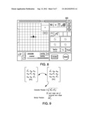
[0054] FIG. 8 shows a screen display 800 in accordance with some embodiments. In this example a status indicator 805 is present in the upper right corner next to the satellite information. When the positioning accuracy is reduced and the user accepts the reduced accuracy, the corresponding threshold icon (Gold, Silver, Bronze) is displayed.
[0055] In some embodiments, the auto-steering system is automatically re-engaged when the positioning accuracy returns to the desired level.
[0056] In some embodiments, the positioning accuracy mode selection is automatically set to a level corresponding to a current level of positioning accuracy. For example, automatic mode selection logic determines the mode when Gold level accuracy drops to Silver or Bronze level accuracy or Silver accuracy drops to Bronze level accuracy. The automatic mode selection logic operates for example as follows: [0057] User selects Gold level positioning accuracy; [0058] When current positioning accuracy drops below Gold level threshold, user is invited to approve automatic change to selection of Silver level positioning accuracy; [0059] User approves automatic change and selected positioning accuracy is changed to Silver level; [0060] Accuracy improves to Gold level for a predetermined time (e.g., 60 seconds)
[0061] Selected positioning accuracy mode automatically returns to previously selected (e.g., Gold) level.
[0062] Positioning quality is in some embodiments based on estimated covariances of parameters used in determining position estimates.
[0063] FIG. 9 shows for example a position covariance matrix from which horizontal precision and/or a vertical precision is estimated. Horizontal precision can be estimated as the square root of the sum of the squares of the East covariance and the North covariance, or as the semi-major axis of a horizontal error ellipse. Vertical precision can be estimated as the square root of the square of the Up covariance. Precisions are typically quoted with a particular confidence level, e.g., 68%, 95%, 99%, etc. Statistics can be scaled to a desired confidence level using an appropriate distribution (e.g., Student-T distribution), assuming the data agrees with the chosen distribution.
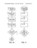
[0064] FIG. 10 shows an example of logic 1000 for determining an accuracy level in accordance with some embodiments. This example is given in the context of the processing techniques described in U.S. Provisional Application for Patent 61/189,382 filed 19 Aug. 2008 (TNL A-2339P) and in International Patent Application PCT/US2009/04476 filed 5 Aug. 2009 (TNL A-2339PCT), International Patent Publication WO2010/021660 dated 25 Feb. 2010, all of which are incorporated herein by this reference. See, for example, the description at pages 32-38 and FIG. 11C of WO2010/021660.
[0065] A weighted average of integer ambiguity candidates ("iFlex" solution) is used to determine a position estimate and position covariance estimates 1005. These are optionally transformed at 1010 to East, North, Up coordinate framework. Horizontal and/or vertical precisions are computed at 1015 from the covariance matrix elements.
[0066] The horizontal and/or vertical precisions are optionally scaled at 1020 to a desired confidence level, e.g., using a particular distribution such as a Fisher F distribution. The horizontal and/or vertical precisions, as optionally scaled, are compared at 1025 to determine if they exceed desired horizontal and/or vertical thresholds. If yes, the solution is reported as "good".
[0067] Covariances are also typically available in RTK processing and can be similarly used. FIG. 11 shows an example of logic 1100 for determining an accuracy level in accordance with some embodiments. This example is given in the context of RTK processing using a fixed integer ambiguity solution.
[0068] A fixed integer ambiguity set is used to determine a position estimate and position covariance estimates 1105. These are optionally transformed at 1110 to East, North, Up coordinate framework. Horizontal and/or vertical precisions are computed at 1115 from the covariance matrix elements.
[0069] The horizontal and/or vertical precisions are optionally scaled at 1120 to a desired confidence level, e.g., using a particular distribution such as a Fisher F distribution. The horizontal and/or vertical precisions, as optionally scaled, are compared at 1125 to determine if they exceed desired horizontal and/or vertical thresholds. If yes, the solution is reported as "good".
[0070] If the selected quality mode allows positioning accuracy to be compromised, the receiver's DOP (dilution of precision) mask can be raised, the C/No (carrier-to-noise ratio) mask can be lowered, and/or satellite geometry can be accepted as less than ideal. Lowering the DOP mask gives better geometry by allowing satellites at a lower elevation to be used in the position solution. Lowering the C/No mask can help when the signal is degraded for example as a satellite signal at the receiver antenna is blocked by a tree or other obstruction; in some embodiments a threshold is set so that a satellite will be dropped from the position solution when the C/No falls below a threshold.
[0071] Some embodiments use a least squares technique to DGPS with sigmas taken from the covariance matrix by taking the square roots of the diagonal elements of the covariance matrix. (A Kalman filter or other suitable processing approach may be used if desired.) Some embodiments use the same technique for corrections from an Omnistar VBS correction stream. Some embodiments use the same technique for corrections from the WAAS correction stream or other SBAS corrections stream.
[0072] Some embodiments use corrections from an Omnistar correction stream and obtain relevant sigmas from a library supplied with the Omnistar correction stream. GNSS observables and the Omnistar HP/XP/G2 correction stream are supplied to a library which provides a position estimate with covariance matrix.
[0073] Some embodiments use a lower accuracy Omnistar VBS correction stream which is processed in the same manner as DGPS correction data.
[0074] Some embodiments base DGPS accuracy or error estimates on DOP value, number of satellites tracked, and age of correction.
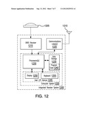
[0075] FIG. 12 is a block diagram of a typical integrated GNSS receiver system 1200 with GNSS antenna 1205 and communications antenna 1210. The Trimble R8 GNSS System is an example of such a system. Receiver system 1200 can serve as a rover or base station or reference station. Receiver system 1200 includes a GNSS receiver 1215, a computer system 1220 and one or more communications links 1225. Computer system 1220 includes one or more processors 1230, one or more data storage elements 1235, program code 1240 with instructions for controlling the processor(s) 1230, and user input/output devices 1245 which may include one or more output devices 1250 such as a display or speaker or printer and one or more devices 1255 for receiving user input such as a keyboard or touch pad or mouse or microphone.
[0076] The inventive concepts can be employed in a wide variety of processes and equipment. Some exemplary embodiments will now be described. It will be understood that these are intended to illustrate rather than to limit the scope of the invention.
[0077] Those of ordinary skill in the art will realize that the detailed description of embodiments of the present invention is illustrative only and is not intended to be in any way limiting. Other embodiments of the present invention will readily suggest themselves to such skilled persons having the benefit of this disclosure.
[0078] In the interest of clarity, not all of the routine features of the implementations described herein are shown and described. It will be appreciated that in the development of any such actual implementation, numerous implementation-specific decisions must be made to achieve the developer's specific goals, such as compliance with application- and business-related constraints, and that these specific goals will vary from one implementation to another and from one developer to another. Moreover, it will be appreciated that such a development effort might be complex and time-consuming, but would nevertheless be a routine undertaking of engineering for those of ordinary skill in the art having the benefit of this disclosure.
[0079] In accordance with embodiments of the present invention, the components, process steps and/or data structures may be implemented using various types of operating systems (OS), computer platforms, firmware, computer programs, computer languages and/or general-purpose machines. The methods can be run as a programmed process running on processing circuitry. The processing circuitry can take the form of numerous combinations of processors and operating systems, or a stand-alone device. The processes can be implemented as instructions executed by such hardware, by hardware alone, or by any combination thereof. The software may be stored on a program storage device readable by a machine. Computational elements, such as filters and banks of filters, can be readily implemented using an object-oriented programming language such that each required filter is instantiated as needed.
[0080] Those of skill in the art will recognize that devices of a less general-purpose nature, such as hardwired devices, field programmable logic devices (FPLDs), including field programmable gate arrays (FPGAs) and complex programmable logic devices (CPLDs), application specific integrated circuits (ASICs), or the like, may also be used without departing from the scope and spirit of the inventive concepts disclosed herein.
[0081] In accordance with an embodiment of the present invention, the methods may be implemented on a data processing computer such as a personal computer, workstation computer, mainframe computer, or high-performance server running an operating system such as a version of Microsoft® Windows® available from Microsoft Corporation of Redmond, Wash., or various versions of the Unix operating system such as Linux available from a number of vendors. The methods may also be implemented on a multiple-processor system, or in a computing environment including various peripherals such as input devices, output devices, displays, pointing devices, memories, storage devices, media interfaces for transferring data to and from the processor(s), and the like. Such a computer system or computing environment may be networked locally, or over the Internet.
[0082] Following is an abbreviated summary of inventive concepts described herein: [0083] 1. A method of reporting quality of GNSS position fixes, comprising: [0084] obtaining a desired quality mode selection, [0085] obtaining position fixes with respective precision estimates and satellite tracking information, [0086] determining for each of a plurality of position fixes a current positioning quality based on the precision estimates and satellite tracking information and quality mode selection, and [0087] reporting current positioning quality. [0088] 2. The method of 1, wherein the quality selection comprises a preference of availability over accuracy, or accuracy over availability, or a balance of availability and accuracy. [0089] 3. The method of 2, wherein obtaining position fixes comprises processing GNSS receiver data subject to at least one control favoring the preference. [0090] 4. The method of 3, wherein the at least one control favoring the preference comprises at least one of: a satellite elevation mask, a C/No (Carrier-to-Noise power ratio) mask, a DOP (Dilution of Precision) mask, a control providing additional accuracy, and a control providing additional availability. [0091] 5. The method of 1, wherein the precision estimate for each position fix is determined from covariances of parameters estimated with the position fix. [0092] 6. The method of one of 1-5, wherein determining the positioning quality comprises at least one of: determining whether satellites are being tracked, determining whether a position fix is being determined, determining whether availability exceeds a threshold, determining whether availability and accuracy are balanced, and determining whether accuracy exceeds a threshold. [0093] 7. The method of one of 1-6, wherein reporting current positioning quality comprises displaying at least one of: an icon indicating current positioning quality, a color indicating current positioning quality, a number of bars indicating whether criteria corresponding to the desired quality mode selection are satisfied [0094] 8. The method of 7, wherein reporting current positioning quality comprises displaying an indication of the desired quality mode selection. [0095] 9. An article of manufacture comprising a computer-readable storage device embodying instructions which enable a processor to perform a method according to one of 1-9. [0096] 10. Apparatus for reporting quality of GNSS position fixes, comprising: [0097] a memory storing a desired quality mode selection, [0098] a memory storing position fixes with respective precision estimates and satellite tracking information, [0099] a processing element to determine for each of a plurality of position fixes a current positioning quality based on the precision estimates and satellite tracking information and quality mode selection, and [0100] a reporting element to report current positioning quality. [0101] 11. The apparatus of 10, wherein the quality selection comprises a preference of availability over accuracy, or accuracy over availability, or a balance of availability and accuracy. [0102] 12. The apparatus of 11, wherein the position fixes are determined from processing of GNSS receiver data subject to at least one control favoring the preference. [0103] 13. The apparatus of 12, wherein the at least one control favoring the preference comprises at least one of: a satellite elevation mask, a C/No (Carrier-to-Noise power ratio) mask, a DOP (Dilution of Precision) mask, a control providing additional accuracy, and a control providing additional availability. [0104] 14. The apparatus of 13, wherein the precision estimate for each position fix is determined from covariances of parameters estimated with the position fix. [0105] 15. The apparatus of one of 11-14, wherein the processing element determines the positioning quality based on at least one of: whether satellites are being tracked, whether a position fix is being determined, whether availability exceeds a threshold, whether availability and accuracy are balanced, and whether accuracy exceeds a threshold. [0106] 16. The apparatus of one of 11-15, wherein the reporting element displays at least one of: an icon indicating current positioning quality, a color indicating current positioning quality, a number of bars indicating whether criteria corresponding to the desired quality mode selection are satisfied. [0107] 17. The apparatus of 16, wherein the reporting element displays an indication of the desired quality mode selection.
User Contributions:
Comment about this patent or add new information about this topic:
| People who visited this patent also read: | |
| Patent application number | Title |
|---|---|
| 20180000214 | TELESCOPICALLY-EXTENDABLE HANDLE AND RECHARGEABLE POWER SUPPLY ASSEMBLY FOR LUGGAGE |
| 20180000213 | HARD-SHELL LUGGAGE SYSTEM HAVING A FRONT ACCESSIBLE RECESSED POUCH |
| 20180000211 | UMBRELLA |
| 20180000210 | SINGLE-POINT SUPPORTIVE MONOCOQUE AMBULATION AID |
| 20180000209 | Jewelry with Exotic Natural Wood and Real Feathers |
Images included with this patent application:
 |  |
 |  |
 |  |
 |  |
| Similar patent applications: | |
| Date | Title |
|---|---|
| 2011-08-18 | Estimating frequency of a gnss enabled device based on time stamps |
| 2009-12-31 | Method and apparatus for mitigating the effects of cross correlation in a gps receiver |
| 2012-12-20 | Dynamic switching to bit-synchronous integration to improve gps signal detection |
| 2009-10-22 | Ambiguity estimation of gnss signals for three or more carriers |
| 2010-02-11 | In-vehicle alert of cloud point in engine diesel fuel |
| New patent applications in this class: | |
| Date | Title |
|---|---|
| 2019-05-16 | Method and apparatus for wireless communication in wireless communication system |
| 2016-12-29 | Detection of parking lot context |
| 2016-05-05 | Methods and apparatus for detecting gnss satellite signals in signal degraded environments |
| 2016-04-28 | Method and system for 3d position estimation of a gnss receiver using travel time measurements |
| 2016-02-04 | Multi-antenna-gnss receiver-system to raise the probability of line of sight |
| New patent applications from these inventors: | |
| Date | Title |
|---|---|
| 2017-06-22 | Gnss signal processing with delta phase |
| 2014-01-16 | Gnss signal processing with ionospheric bridging for reconvergence |
| 2014-01-02 | Gnss signal processing with known position for reconvergence |
| 2013-12-19 | Gnss signal processing with delta phase for incorrect starting position |
| 2012-12-06 | Gnss signal processing with regional augmentation message |
| Top Inventors for class "Communications: directive radio wave systems and devices (e.g., radar, radio navigation)" | |
| Rank | Inventor's name |
|---|---|
| 1 | Charles Abraham |
| 2 | Frank Van Diggelen |
| 3 | Dominic Gerard Farmer |
| 4 | Farshid Alizadeh-Shabdiz |
| 5 | Ulrich Vollath |