Patent application title: PORTABLE DEVICE FOR LIQUID AND SEMI-LIQUID REMOVAL AND METHOD THEREOF
Inventors:
Joseph Fraser (Acworth, GA, US)
IPC8 Class: AE03B500FI
USPC Class:
13756501
Class name: Fluid handling systems with pump
Publication date: 2012-05-17
Patent application number: 20120118411
Abstract:
A portable device for liquid and semi-liquid removal and method therein
having a receptacle, lid assembly, vacuum attachment assembly, intake
attachment assembly, intake system, and a vacuum system, wherein the lid
assembly fastens to the receptacle and connects the intake system and the
vacuum system to the receptacle.Claims:
1. A portable device for liquid removal, comprising: a receptacle; a lid
dimensioned to attach to said receptacle; a means for producing a suction
in said receptacle; and a means for fluid communication with the liquid
to be removed and said receptacle.
2. The portable device for liquid removal of claim 1, wherein said means for producing a suction is a vacuum.
3. The portable device for liquid removal of claim 1, wherein said means for producing a suction is a pump.
4. The portable device for liquid removal of claim 1, wherein said means for fluid communication is a hose.
5. The portable device for liquid removal of claim 1, wherein said lid comprises a first port and a second port, wherein said mean for producing a suction is attachable to said first port and said means for fluid communication is attachable to said second port.
6. The portable device for liquid removal of claim 5, further comprising a shut-off valve carried by said means for fluid communication.
7. The portable device for liquid removal of claim 5, wherein said second port comprises an elbow joint positioned such that the entering fluid is directed away from said first port.
8. A means for removing waste from a holding tank, comprising the steps of: a. obtaining a receptacle comprising a lid having a first port and a second port, wherein a vacuum source is attached to said first port and a hose is attached to said second port; b. attaching said hose to the holding tank; c. energizing said vacuum to produce a suction within said receptacle, wherein the waste from the holding tank travels into said receptacle via said hose; and d. de-energizing said vacuum upon removal of the waste.
9. The means of claim 8, further comprising the steps of: a. disconnecting said hose from the holding tank; and b. transporting said receptacle having the waste therein to a suitable waste disposal location and disposing the waste therein.
10. A portable device for liquid removal, comprising: a receptacle; a lid dimensioned to attach to said receptacle, wherein said lid comprises a first port and a second port; a vacuum in communication with said first port; and a hose having a first end and a second end, wherein said first end is in fluid communication with the liquid to be removed and said second end is in fluid communication with said second port.
11. The portable device for liquid removal of claim 10, further comprising a shut-off valve in fluid communication with said hose.
12. The portable device for liquid removal of claim 10, wherein said second port comprises an elbow joint positioned such that the entering fluid is directed away from said first port.
Description:
TECHNICAL FIELD
[0001] The present disclosure relates generally to a device for liquid removal and more particularly to a portable device for waste removal and method therein.
BACKGROUND
[0002] Many people enjoy exploring and immersing themselves in the great outdoors. Such explorations may be experienced via a recreational vehicle such as a motor home, a fifth-wheel traveler, or a camper. Alternatively, some people's explorations find themselves exploring water worlds via a boat, yacht, or even larger marine vessel. While most people tend to remember the positive aspects of owning a recreational vehicle or a boat, there are some necessary and potentially negative aspects of owning these vehicles.
[0003] For example, when a trip on a boat or recreational vehicle is completed, the head reservoir or holding tank on a boat or a recreational vehicle, respectively, needs to be emptied and properly discarded. The cost associated with waste removal for boat and/or recreational vehicle owners is expensive and inconvenient considering dump stations are typically limited to marinas and RV camps, respectively. Furthermore, considering the high cost and inconvenience associated with waste removal for boats and recreational vehicles, a typical alternative performed to circumvent these obstacles is the improper waste removal and disposal into the environment. Due to the inconvenience and clean-up required in some cases small recreational boat users avoid using the built in facilities and resort to relieving themselves directly into the water. This practice harms the environment boat and recreational vehicle enthusiasts seek to enjoy.
[0004] There have been attempts to develop a device to aid in self removal of waste from a head reservoir or hold tank. For example, a device was developed that collected waste from reservoirs and hold tanks. The design included a rectangular catch tray set on wheels and was designed to collect the liquid waste from the holding tank or reservoir using only gravity that could be then transported to a waste receptacle. There are flaws concerning this design that needed to be addressed. For example, the device did not include a system or method for removing the waste from the reservoirs or hold tanks including boat and/or recreational vehicle attachments, liquid transport tubes, or a vacuum system that provided necessary lift to removed the liquid waste.
[0005] As such, it is clear that there is an unmet need for a portable device for liquid removal and method therein which provides an alternative to consumers whereby the device removes liquids such as human waste from a head or holding tank in a timely, cost effective, and environment friendly manner.
SUMMARY
[0006] Briefly described, in a preferred embodiment, the portable device for liquid removal and method therein of the present disclosure overcomes the above-mentioned disadvantages and meets the recognized need for such a device by providing a portable device for liquid removal and method therein having a receptacle, lid assembly, vacuum attachment assembly, intake attachment assembly, intake system, and a vacuum system.
[0007] More specifically, the receptacle preferably has cylindrical shape and collects liquid for disposal. The lid assembly preferably fastens to the receptacle and preferably connects the intake system and the vacuum system to the receptacle. A vacuum source such as a shop vacuum preferably attaches to the vacuum system providing suction; the driving force for the device. After proper assembly and after the vacuum source is turned on, a suction force begins throughout the device removing the unwanted waste from a reservoir or holding tank then depositing the waste into a special container rather than soiling the shop vacuum with human waste. The lid assembly preferably has shut off valves located in the vacuum attachment assembly and the intake assembly for easy transport to a proper home waste receptacle such as a toilet. Furthermore, the intake assembly contains preferably a curved elbow intake port, located on the interior of the lid assembly, to direct incoming liquid away from the vacuum line in the receptacle and a check valve preventing the liquid from a full canister from entering and potentially damaging the vacuum source.
BRIEF DESCRIPTION OF THE DRAWINGS
[0008] Accordingly, the present disclosure will be understood best through consideration of, and with reference to, the following drawing Figures, viewed in conjunction with the Detailed Description referring thereto, in which like reference numbers throughout the various Figures designate like structure, and in which:
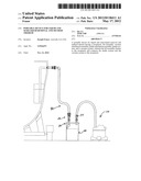
[0009] FIG. 1 is a perspective view of the portable device for liquid removal and method therein shown in an attached position;
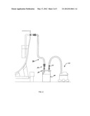
[0010] FIG. 2 is a side view of the portable device for liquid removal and method therein shown in an attached position;;
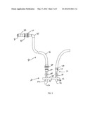
[0011] FIG. 3 is a side view of the lid assembly of the device of FIG. 1;
[0012] It is to be noted that the drawings presented are intended solely for the purpose of illustration and that they are, therefore, neither desired nor intended to limit the invention to any or all of the exact details of construction shown, except insofar as they may be deemed essential to the claimed invention.
DETAILED DESCRIPTION OF ILLUSTRATIVE EMBODIMENTS
[0013] In describing preferred embodiment of the portable device for liquid removal and method therein of the present invention illustrated in the Figures, specific terminology is employed for the sake of clarity. The claimed invention, however, is not intended to be limited to the specific terminology so selected, and it is to be understood that each specific element includes all technical equivalents that operate in a similar manner to accomplish a similar purpose.
[0014] As shown in FIGS. 1-3, the portable liquid removal device 10 preferably comprises waste receptacle 20, lid assembly 30, intake attachment assembly 50, vacuum attachment assembly 70, intake system 90, and vacuum system 110.
[0015] Receptacle 20 preferably comprises receptacle bottom 22, circumferential wall 24, and upper lip 25, thereby forming a receptacle interior. Bottom 22 and circumferential wall 24 are connected to preferably form a cylindrical receptacle for liquid collection. Upper lip 25 of receptacle 20 is dimensioned to receive lid assembly 30 thus sealing the receptacle interior.
[0016] Lid assembly 30 preferably comprises lid exterior 32, lid interior 34, and lid lip 36. Lid assembly 30 preferably has two holes allowing attachment of intake attachment assembly 50 and vacuum attachment assembly 70 to lid assembly 30. Lid interior 34 and lid lip 36 are placed on receptacle 20 and in conjunction with upper lip 25 of receptacle 20 to seal the interior of receptacle 20. Furthermore, lid assembly 30 provides a junction where intake system 90 and vacuum system 110 interface with receptacle 20 and the receptacle interior.
[0017] As shown in FIG. 3, intake attachment assembly 50 preferably comprise exterior male union 52, intake transport tube 54, elbow port 56, and shut off valve 58. Exterior male union 52 preferably connects with female union 98 of intake system 90. Intake transport tube 54 allows passage of liquid through lid assembly 30 and into the receptacle interior of receptacle 20. Elbow port is preferably oriented in the receptacle interior such that incoming liquid into receptacle 20 directs away from vacuum attachment assembly 70 preventing waste from entering vacuum attachment assembly 70 and thus the vacuum source. Intake transport tube 54 preferably contains shut off valve 58. Shut off valve 58 preferably seals off intake attachment assembly 50 and receptacle 20 during liquid transport to a receptacle.
[0018] Shown in FIG. 1-3, vacuum attachment assembly 70 preferably comprise exterior vacuum source attachment 72, bypass vent 74, vacuum tube 76, shut off valve 78, and interior suction port 80. Exterior vacuum source attachment 72 connects the device to a vacuum source such as a shop vac. Vacuum tube 76 connects exterior vacuum source attachment 72 to interior suction port 80 in the receptacle interior. Within exterior vacuum attachment 72 preferably exists bypass vent 74 and shut off valve 78. Shown in FIG. 3, bypass valve 74 allows air to circulate into the vacuum source to prevent overheating of the vacuum source. Shut off valve 78 preferably seals off vacuum attachment assembly 70 during liquid transport to a receptacle.
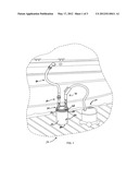
[0019] As seen in FIG. 3, intake system 90 preferably comprises adapter 92, distal female union 94, intake transport tube 96, optional elbow joint 95 and proximal female union 98. Adapter 92 preferably comprises first male end 91 and second male end 93, wherein first male end 91 connects to the head reservoir or holding tank port on the boat or RV and second male end 93 connects to distal female union 94 which connects with intake transport tube 96. Proximal male union 98 preferably connects exterior male union 52 of intake attachment assembly 50.
[0020] During use, intake system 90 is attached to the holding tank to be emptied and valves 58 and 78 are opened. Vacuum system 110 is then energized until the desired amount of waste is removed. Next, valves 58 and 78 are closed and the intake system 90 and the vacuum system 110 are removed. Receptacle 20 can then be transported to a desired location and emptied.
User Contributions:
Comment about this patent or add new information about this topic:
| People who visited this patent also read: | |
| Patent application number | Title |
|---|---|
| 20170045717 | OPTICAL SYSTEM |
| 20170045716 | Optical Image Capturing System |
| 20170045715 | Optical Image Capturing System |
| 20170045714 | PHOTOGRAPHING OPTICAL LENS ASSEMBLY, IMAGE CAPTURING UNIT AND ELECTRONIC DEVICE |
| 20170045713 | OPTICAL IMAGING LENS |
Images included with this patent application:
 |  |
 |  |
| Similar patent applications: | |
| Date | Title |
|---|---|
| 2011-12-08 | Rescue device for leakage of dangerous chemicals (as amended) |
| 2012-10-04 | Method for temporarily interrupting an extracorporeal blood treatment, control device and blood treatment apparatus |
| 2010-12-30 | Device for metering a liquid reducing agent |
| 2012-07-26 | Device for ventilating and aerating a fuel tank |
| 2010-02-18 | Feeding device for liquid materials |
| New patent applications in this class: | |
| Date | Title |
|---|---|
| 2016-06-30 | Apparatus, system and method for conserving water |
| 2016-06-23 | Mixing valve |
| 2016-06-23 | Pump system including valve cartridge assembly with a suction valve in line with a discharge valve |
| 2016-06-23 | Method and system for recovering, and displacing fluid from, a pipe |
| 2016-06-09 | Mineral water supply module |
| Top Inventors for class "Fluid handling" | |
| Rank | Inventor's name |
|---|---|
| 1 | Nobukazu Ikeda |
| 2 | Kouji Nishino |
| 3 | Ryousuke Dohi |
| 4 | Kevin T. Peel |
| 5 | Huasong Zhou |