Patent application title: COOLING DEVICE
Inventors:
Xian-Xiu Tang (Shenzhen City, CN)
Assignees:
HON HAI PRECISION INDUSTRY CO., LTD.
HONG FU JIN PRECISION INDUSTRY (ShenZhen) CO., LTD.
IPC8 Class: AF28D1500FI
USPC Class:
16510431
Class name: Liquid fluent heat exchange material including means to move heat exchange material by application of mechanical energy
Publication date: 2012-05-03
Patent application number: 20120103575
Abstract:
An exemplary cooling device includes a heat dissipating member, a pump, a
heat absorbing member defining a receiving chamber containing coolant
therein, and a liquid input conduit and a liquid output conduit
connecting the heat absorbing member, the heat dissipation member and the
pump together to form a heat transfer loop. The heat absorbing member
have at a first side and a second side opposite to the first side. The
heat absorbing member defines a heating area at the first side. The
heating area is configured to contact a heat generating component for
absorbing heat generated by the heat generating component. The heat
absorbing member includes at the second side a liquid inlet aligned with
the heating area and liquid outlets around the liquid inlet.Claims:
1. A cooling device, comprising: a heat dissipating member; a pump; a
heat absorbing member defining a receiving chamber for containing coolant
therein, the heat absorbing member having at a first side and a second
side opposite to the first side, the heat absorbing member defining a
heating area at the first side, the heating area configured to contact a
heat generating component for absorbing heat generated by the heat
generating component, the heat absorbing member comprising at the second
side a liquid inlet aligned with the heating area and a plurality of
liquid outlets around the liquid inlet; and a liquid input conduit and a
liquid output conduit connecting the heat absorbing member, the heat
dissipation member and the pump together to form a heat transfer loop.
2. The cooling device of claim 1, wherein the heat absorbing member comprises a bottom plate and a cover covered on the bottom plate, the heating area is formed at a central portion of the bottom plate, and the liquid inlet and the liquid outlets are defined in the cover.
3. The cooling device of claim 1, wherein the plurality of liquid outlets comprises two in number, the liquid outlets are arranged symmetrically at two sides of the liquid inlet.
4. The cooling device of claim 3, wherein the liquid output conduit comprises a first pipe connected with the heat dissipation element and two second pipes connected with the liquid outlets of the heat absorbing member.
5. The cooling device of claim 4, wherein the liquid output conduit comprises a Y-junction connector connected the first pipe and the second pipes together, the Y-junction connector defining a first end connected with the first pipe and two second ends connected with the second pipes, respectively, at distal ends thereof.
6. The cooling device of claim 3, wherein the liquid output conduit overall is Y-shaped.
7. The cooling device of claim 1, wherein the liquid output conduit comprises a first pipe connected with the heat dissipation member and a plurality of second pipes connected with the liquid outlets of the heat absorbing member, respectively.
8. The cooling device of claim 1, wherein each of the liquid inlet and the liquid outlets comprises a plurality of female threads at inner surface thereof, the heat absorbing member comprising a plurality of connecting units threaded on the liquid inlet and the liquid outlets, respectively, each of the connecting units comprising a fastener and a threaded cap around the fastener, the fastener defining a through hole communicated with the receiving chamber of the heat absorbing member along an axis thereof, an annular space being defined between the fastener and the threaded cap of each connecting unit for inference connecting with a corresponding liquid output conduit or a corresponding liquid input conduit.
9. The cooling device of claim 1, wherein the heat absorbing member comprises a fin unit arranged right above the heating area.
10. The cooling device of claim 9, wherein the fin unit comprises a plurality of fins stacked together, each two neighboring fins defining a flow channel therebetween, the liquid inlet and the liquid outlets arranged in a line, each of the flow channels extending along an axis along which the liquid inlet and the liquid outlets are arranged.
11. The cooling device of claim 9, wherein the heat sink is immersed in the coolant contained in the receiving chamber.
12. A cooling device, comprising: a heat dissipating member; a pump; a heat absorbing member comprises a bottom plate and a cover attached on the bottom plate, a receiving chamber defined between the bottom plate and the cover for containing coolant therein, a heating area of the bottom plate configured to contact a heat generating component for absorbing heat generated by the heat generating component, the cover comprising a liquid inlet aligned with the heating area and a plurality of liquid outlets around the liquid inlet; and a liquid input conduit and a liquid output conduit connecting the heat absorbing member, the heat dissipation member and the pump together to form a heat transfer loop; wherein the coolant is driven by the pump to circulate through heat transfer loop, whereby the coolant takes the heat from the heat absorbing member to the heat dissipating member for dissipating.
13. The cooling device of claim 12, wherein the heat absorbing member comprises a fin unit arranged right above the heating area.
14. The cooling device of claim 13, wherein the fin unit comprises a plurality of fins stacked together, each two neighboring fins defining a flow channel therebetween, the liquid inlet and the liquid outlets arranged in a line, each of the flow channels extending along an axis along which the liquid inlet and the liquid outlets are arranged.
15. The cooling device of claim 13, wherein the heat sink is immersed in the coolant contained in the receiving chamber.
16. The cooling device of claim 12, wherein the plurality of liquid outlets comprises two in number, the liquid outlets are arranged symmetrically at two sides of the liquid inlet.
17. The cooling device of claim 16, wherein the liquid output conduit overall is Y-shaped, and comprises a first pipe connected with the heat dissipation element and two second pipes connected with the liquid outlets of the heat absorbing member.
18. The cooling device of claim 17, wherein the liquid output conduit comprises a Y-junction connector connected the first pipe and the second pipes together, the Y-junction connector defining a first end connected with the first pipe and two ends connected with the second pipes, respectively, at distal ends thereof.
19. The cooling device of claim 12, wherein each of the liquid inlet and the liquid outlets comprises a plurality of female thread at inner surface thereof, the heat absorbing member comprising a plurality of connecting units threaded on the liquid inlet and the liquid outlets, respectively, each of the connecting units comprising a fastener and a threaded cap around the fastener, the fastener defining a through hole communicated with the receiving chamber of the heat absorbing member along an axis thereof, an annular space being defined between the fastener and the threaded cap of each connecting unit for inference connecting with a corresponding liquid output conduit or a corresponding liquid input conduit.
Description:
BACKGROUND
[0001] 1. Technical Field
[0002] The disclosure generally relates to temperature control of operating electronic devices, and more particularly to a cooling device for a heat generating electronic component such as a central processing unit (CPU).
[0003] 2. Description of Related Art
[0004] As a result of the higher operating frequencies and faster speed of modern CPUs, heat generated by these CPUs during their operation is commensurately higher. If the generated heat is not quickly removed, the CPU can overheat, and the workability and stability of the CPU may be adversely affected.
[0005] In order to remove heat from CPUs, cooling devices are often provided. A heat sink combined with an electric fan is typically used, and this arrangement can achieve good heat dissipation. Conventional cooling devices are sufficient for CPUs running at average operating frequencies, but are liable to be unsatisfactory for cooling CPUs operating at high frequencies.
[0006] Various kinds of cooling devices with enhanced heat dissipation efficiency are used for dissipating heat generated by CPUs operating at high frequency. A typical such cooling device includes a heat-absorbing member, a heat-dissipating member, a pump driving a coolant between the heat-absorbing member and the heat-dissipating member, and a plurality of tubes connecting the heat-absorbing member, the pump and the heat-dissipating member in a loop. In use, the heat-absorbing member is maintained in thermal contact with the CPU for absorbing heat generated by the CPU. The coolant is driven by the pump to circulate between the heat-absorbing member and the heat-dissipating member to continuously evacuate heat absorbed by the heat-absorbing member to the heat-dissipating member for dispersal.
[0007] In such a cooling device, the heat-absorbing member is generally a solid metal block with a liquid flow channel defined therein for passage of the coolant. As the coolant flows through the liquid flow channel, the heat of the CPU is absorbed by the coolant. However, a wall of the liquid flow channel has a relatively small heat exchange surface with the coolant, and therefore the heat flux density between the heated area of the heat-absorbing member and the coolant is limited. That is, the heat-absorbing member may not be able to exchange heat efficiently with the coolant. As a result, the heat of the CPU cannot be adequately transferred to the coolant of the heat-absorbing member and timely evacuated by the cooling device.
[0008] What is desired, therefore, is a cooling device which can overcome the described limitations.
BRIEF DESCRIPTION OF THE DRAWINGS
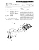
[0009] FIG. 1 is an isometric, assembled view of a cooling device according to an exemplary embodiment of the present disclosure.
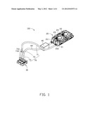
[0010] FIG. 2 is an enlarged view of a heat absorbing member of the cooling device of FIG. 1.
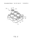
[0011] FIG. 3 is an exploded view of the heat absorbing member of FIG. 2.
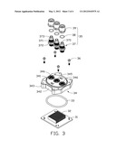
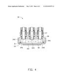
[0012] FIG. 4 is a cross-section of the heat absorbing member of FIG. 2, taken along line IV-IV thereof.
DETAILED DESCRIPTION
[0013] Reference will now be made to the figures to describe the present cooling device in detail.
[0014] Referring to FIG. 1, a cooling device 100 according to an exemplary embodiment of the present disclosure includes a heat dissipation member 20, a heat absorbing member 30, a pump 40, and a liquid input conduit 60 and a liquid output conduit 70 connecting the heat dissipating member 20, the heat absorbing member 30, and the pump 40 in a loop.
[0015] The heat absorbing member 30 thermally contacts a heat generating component 80 (see FIG. 4), such as a CPU, for absorbing heat generated therefrom. Referring also to FIGS. 2 and 3 together, the heat absorbing member 30 includes a bottom plate 31, a fin unit 32, a sealing ring 33, a cover 34 and three connecting units 35.
[0016] The bottom plate 31 is made of thermally conductive material, such as copper or aluminum. The cover 34 includes a substantially circular top plate 341, a side plate 342 depending from an outer periphery of the top plate 341, and four fixing portions 343 equally spaced from each other extending outwardly from the side plate 342. The top plate 341 defines a circular liquid inlet 345 at a central portion thereof, and two circular liquid outlets 346 at two opposite sides of the liquid inlet 345. The liquid inlet 345 and the liquid outlets 346 are aligned with each other. Each of the liquid inlet 345 and the liquid outlets 346 includes a plurality of female threads at an inner surface thereof. The fin unit 32 includes a plurality of fins stacked together, and is soldered to a top surface of the bottom plate 31. The fin unit 32 defines a plurality of flow channels between each two neighboring fins. Each of the flow channels is wide and shallow, wherein a direction of flow of liquid in the flow channel is parallel to axes along which the liquid inlet 345 and the liquid outlets 346 are arranged, respectively.
[0017] Referring to FIG. 4, a central portion of a bottom surface of the bottom plate 31 of the heat absorbing member 30 contacts the heat generating component 80, to form a heating area 310 at the central portion of the bottom surface of the bottom plate 31. The fin unit 32 is located right above the heating area 310 of the bottom plate 31. The cover 34 is covered on the bottom plate 31, with the liquid inlet 345 aligned with the heating area 310 and the two liquid outlets 346 arranged at two opposite ends of the flow channels of the fin unit 32, respectively. The bottom of the side plate 342 connects the top surface of the bottom plate 31, with a plurality of bolts 36 respectively extending through the fixing portions 343 and the bottom plate 31 and thereby connecting the cover 34 and the bottom plate 31. The sealing ring 33 is sandwiched between the bottom of the side plate 342 and the bottom plate 31, such that the cover 34 is hermetically mounted to the bottom plate 31 to define a receiving chamber 348 therebetween. The heat absorbing member 30 contains coolant, such as water, in the receiving chamber 348, with the fin unit 32 being immersed in the coolant.
[0018] Each of the connecting units 35 includes a fastener 37, a threaded cap 39 and a sealing ring 38. The fastener 37 includes a cylindrical fixing post 371, an annular protruding flange 372 extending radially and outwards from an outer surface of a middle portion of the fixing post 371, and a head portion 373 located at a top end of the fixing post 371. The fastener 37 defines a through hole 370 at a middle portion along an axis thereof. A plurality of first male threads is formed at an outer surface of a lower portion of the fixing post 371 below the protruding flange 372. The first male threads of the fixing posts 371 correspond to the female threads of the liquid inlet 345 and the liquid outlets 346, respectively. A plurality of second male threads is formed at an outer surface of an upper portion of the fixing post 371 of each fastener 37, above the protruding flange 372.
[0019] Each of the threaded caps 39 is hollow and cylindrical, and defines a plurality of female threads at an inner surface thereof. The female threads of the threaded caps 39 correspond to the second male threads of the fixing posts 371, respectively. Each threaded cap 39 has an inner diameter larger than an outer diameter of the corresponding head portion 373. When each connecting unit 35 is assembled, the threaded cap 39 extends higher than the upper portion of the corresponding fixing post 371. When the heat absorbing member 30 is assembled, the fasteners 37 are threaded onto the liquid inlet 345 and the liquid outlets 346 of the heat absorbing member 30 via the lower portions of the fixing posts 371, respectively. The sealing rings 38 are respectively sandwiched between the fixing posts 371 and the liquid inlet 345 and the liquid outlets 346 of the heat absorbing member 30, so that the connecting units 35 are hermetically mounted to the cover 34. The threaded caps 38 are threaded onto the upper portions of the fixing posts 371 of the fasteners 37, respectively, with an annular space 374 defined between an upper portion of the inner surface of each threaded cap 39 and the outer surface of the corresponding head portion 373. A transverse width of the annular space 374 as measured along a radius of the connecting unit 35 is substantially equal to a thickness of a wall of the liquid input conduit 60 and a thickness of a wall of the liquid output conduit 70.
[0020] The heat dissipation member 20 includes a tank 21, a plurality of tubes 23 connected to the tank 21, a plurality of heat dissipation sheets 22 mounted around the tubes 23, and two fans 24 mounted at the top of the heat dissipation sheets 22. The tank 21 defines a liquid intake 212 and a liquid outflow 211 at one side thereof. The tubes 23 connect with another side of the tank 21 opposite to the side where the liquid intake 212 and the liquid outflow 211 are located.
[0021] Referring back to FIG. 1, the liquid input conduit 60 is longitudinal. One end of the liquid input conduit 60 is interference fitted into the annular space 374 of the connecting unit 35 connected with the liquid inlet 346, and another end of the liquid input conduit 60 is connected with liquid outflow 211 of the tank 21. The pump 40 connects with the liquid input conduit 60 and is located between the liquid inlet 345 of the heat absorbing member 30 and the liquid outflow 211 of the heat dissipation member 20. The liquid output conduit 70 includes a longitudinal first pipe 71, a Y-junction connector 72 and two second pipes 73. The Y-junction connector 72 is Y-shaped, and includes a first end 710 and two second ends 730. The first pipe 71 is connected between the first end 710 and the liquid intake 212. Each of the second pipes 73 has one end connected with a corresponding second end 730 of the Y-junction connector 72, and another end interference inserted into the annular space 374 of a corresponding connecting unit 35 connected with one of the liquid outlets 346. The liquid output conduit 70 overall is Y-shaped.
[0022] Alternatively, the number of liquid outlets 346 defined in the heat absorbing member 30 can be varied, with the number of second pipes 73 of the liquid output conduit 70 varying correspondingly.
[0023] In operation of the cooling device 100, the heat absorbing member 30 is maintained in thermal contact with the heat generating component 80. In particular, the heating area 310 of the bottom plate 31 of the heat absorbing member 30 is brought into contact with the heat generating component 80. Heat generated by the heat generating component 80 is transferred to and absorbed by the heating area 310 and the fin unit 32 located above the heating area 310. The coolant received in the receiving chamber 348 of the heat absorbing member 30 exchanges heat with the fin unit 32, and the fin unit 32 releases the heat to the coolant. Additionally, the heat absorbed by the heating area 310 is conducted to other portions of the bottom plate 31 and further directly released from the bottom plate 31 to the coolant. After the coolant receives the heat from the fin unit 32 and the bottom plate 31, the coolant is driven by the pump 40 to move towards the heat dissipating member 20 via the liquid output conduit 70. When the coolant reaches the heat dissipating member 20, the heat is dissipated to the ambient environment. After releasing the heat in the heat dissipating member 20, the coolant is brought back to the heat absorbing member 30 via the liquid input conduit 60 again by the pump 40, thus continuously taking the heat away from the heat generating component 80.
[0024] In the present cooling device 100, the liquid inlet 345 is aligned with the heating area 310, and the fin unit 32 is located right above the heating area 310. Therefore the coolant brought back to the heat absorbing member 30 via the liquid inlet 345 can flow directly to and contact the heating area 310 and the fin unit 32 to exchange heat with the heat generating component 80. Thus, total heat exchange efficiency between the coolant and the heat generating component 80 is greatly enhanced. Due to the liquid inlet 345 and the liquid outlets 346 being arranged parallel to the flow channels of the fin units 32, and due to the liquid outlets 346 being arranged symmetrically at two opposite sides of the liquid inlet 345, the flow of coolant after heat exchange with the heat generating component 80 is enhanced. In particular, after the coolant contacts the fin unit 32 and the heating area 345, the coolant is guided to the two liquid outlets 346 which are located at two opposite sides of the heating area 310 via the flow channels of the fin unit 32, and then smoothly flows out of the heat absorbing member 30 via the two liquid outlets 346. Thus, a smooth flow path for the coolant is formed in the receiving chamber 348 of the heat absorbing member 30, to enhance circulation of the coolant in the cooling device 100. Accordingly, the heat of the heat generating component 80 is evacuated quickly and efficiently.
[0025] It is to be understood, however, that even though numerous characteristics and advantages of the embodiments have been set forth in the foregoing description, together with details of the structures and functions of the embodiments, the disclosure is illustrative only, and changes may be made in detail, especially in matters of shape, size, and arrangement of parts within the principles of the disclosure to the full extent indicated by the broad general meaning of the terms in which the appended claims are expressed.
User Contributions:
Comment about this patent or add new information about this topic:
Images included with this patent application:
 |  |
 |  |
 |
| Similar patent applications: | |
| Date | Title |
|---|---|
| 2008-11-20 | Cooling device |
| 2008-12-04 | Cooling device for cpu |
| 2009-02-19 | Air cooling device |
| 2009-03-12 | Cooling device |
| 2009-06-11 | Cooling device |
| New patent applications in this class: | |
| Date | Title |
|---|---|
| 2019-05-16 | Multifunction coolant manifold structures |
| 2019-05-16 | Multifunction coolant manifold structures |
| 2018-01-25 | Water pump cooler for cpu |
| 2017-08-17 | Energy storage device for temporarily storing thermal energy, power plant having an energy storage device, and method for operating an energy storage device |
| 2016-12-29 | Bendable water-cooling device |
| New patent applications from these inventors: | |
| Date | Title |
|---|---|
| 2014-03-20 | Computer enclosure and fan mounting apparatus |
| 2013-12-05 | Water tank for water-cooling heat dissipation system |
| 2013-09-26 | Server cabinet |
| 2013-09-12 | Server cabinet |
| 2013-06-27 | Cabinet with cooling system |
| Top Inventors for class "Heat exchange" | |
| Rank | Inventor's name |
|---|---|
| 1 | Levi A. Campbell |
| 2 | Chun-Chi Chen |
| 3 | Tai-Her Yang |
| 4 | Robert E. Simons |
| 5 | Richard C. Chu |