Patent application title: SYSTEM AND METHOD FOR CLEANING A BOTTOM-HOLE FORMATION ZONE OF A WELLBORE
Inventors:
Marat Shatikovich Gamerov (Leninogrosk, RU)
Ildar Mavletovich Yafarov (Leninogorsk, RU)
Evgeniy Nikolaevich Denisov (Leninogorsk, RU)
IPC8 Class: AE21B3700FI
USPC Class:
166311
Class name: Wells processes cleaning or unloading well
Publication date: 2011-12-29
Patent application number: 20110315387
Abstract:
A system for cleaning a bottom-hole formation zone of a wellbore
comprises a flow string for extending into the bottom-hole formation zone
of the wellbore. A hydrostatic joint is disposed along the flow string.
The hydrostatic valve includes a valve which controls the flow of fluid
through the flow string. There is a fluid supply for discharging fluid
into the wellbore around the flow string to create a hydrostatic pressure
differential between the flow string and the wellbore. Fluid and
suspended solids in the bottom-hole formation zone of a wellbore are
prevented from flowing into the flow string when the valve is closed.
However, fluid and suspended solids in the bottom-hole formation zone of
a wellbore are permitted to flow into the flow string when the valve is
open.Claims:
1. A system for cleaning a bottom-hole formation zone of a wellbore, the
system comprising: a flow string for extending into the bottom-hole
formation zone of the wellbore; a hydrostatic joint disposed along the
flow string, the hydrostatic joint having a valve for controlling the
flow of fluid through the flow string; and a source of fluid for
discharging fluid into the wellbore about the flow string to create a
hydrostatic pressure differential between the flow string and the
wellbore, wherein fluid and suspended solids from the bottom-hole
formation zone of the wellbore are prevented from flowing into the flow
string when the valve is closed, and fluid and suspended solids from the
bottom-hole formation zone of a wellbore are permitted to flow into the
flow string when the valve is open.
2. The system as claimed in claim 1 further including a sump in fluid communication with the flow string.
3. The system as claimed 1 in wherein the flow string further includes a filter disposed adjacent a distal end of the flow string.
4. The system as claimed in claim 1 wherein the flow string further includes a drill bit disposed adjacent a distal end of the flow string.
5. The system as claimed in claim 1 wherein the flow string further includes a centralizer disposed between a distal end of the flow string and the hydrostatic joint.
6. The system as claimed in claim 1 wherein the flow string further includes a check valve disposed between a distal end of the flow string and the hydrostatic joint.
7. The system as claimed in claim 1 wherein the flow string further includes a drain valve disposed between a proximal end of the flow string and the hydrostatic joint.
8. The system as claimed in claim 1 further including a thermochemical cartridge coupled to the flow string.
9. The system as claimed in claim 8 wherein the thermochemical cartridge includes a combustible diaphragm which separates a pressurized chamber from a combustible composite material.
10. The system as claimed in claim 9 wherein the combustible composite material produces hydrochloric acid when combusted.
11. The system as claimed in claim 9 wherein the combustible composite material produces hydrofluoric acid when combusted.
12. The system as claimed in claim 9 wherein the combustible composite material is not explosive.
13. The system as claimed in claim 9 wherein the thermochemical cartridge further includes a fuse for igniting the combustible composite material.
14. The system as claimed in claim 1 wherein the flow string extends from a head and the flow string includes: a first tubing section extending between the head and a drain valve; a second tubing section extending between the drain valve and the hydrostatic joint; a third tubing section extending between the hydrostatic joint and a check valve; and a fourth tubing section extending between the check valve and a filter.
15. A method for cleaning a bottom-hole formation zone of a wellbore comprises the steps of: extending a flow string into the bottom-hole formation zone of the wellbore, the flow string having a valve for controlling the flow of fluid and suspended solids from the bottom-hole formation zone of the wellbore through the flow string; discharging fluid into the wellbore around the flow string to create a hydrostatic pressure differential between the flow string and the wellbore; and opening the valve to allow fluid and suspended solids from the bottom-hole formation zone of a wellbore to flow into the flow string.
16. The method as claimed in claim 15 further including the step of placing the flow string in communication with a sump.
17. The method as claimed in claim 15 further including the step of combusting a composite material prior to opening the valve to increase the temperature and pressure in the bottom-hole formation zone of the wellbore.
18. The method as claimed in 15 further including the step of imploding a pressurized chamber prior to opening the valve to cause a sudden pressure drop in the bottom-hole formation zone of the wellbore.
19. The method as claimed in claim 15 further including the step of withdrawing the flow string from the bottom-hole formation zone of the wellbore while the flow string contains fluid and suspended solids from the bottom-hole formation zone of a wellbore.
20. A system for cleaning a wellbore, the system comprising: a flow string for extending into the wellbore; a hydrostatic joint disposed along the flow string, the hydrostatic joint having a valve for controlling the flow of fluid through the flow string; and a source of fluid for discharging fluid into the wellbore about the flow string to create a hydrostatic pressure differential between the flow string and the wellbore, wherein fluid and suspended solids from the wellbore are prevented from flowing into the flow string when the valve is closed, and fluid and suspended solids from the wellbore are permitted to flow into the flow string when the valve is open.
Description:
BACKGROUND OF THE INVENTION
[0001] 1. Field of the Invention
[0002] The present invention relates to a system and method for cleaning a wellbore and, in particular, to a system and method for cleaning a bottom-hole formation zone of a wellbore.
[0003] 2. Description of the Related Art
[0004] It is known that a decrease in the permeability of the bottom-hole formation zone of a wellbore may result in a decrease in hydrocarbon recovery. The decrease in the permeability of the bottom-hole formation zone may be the result of dilatation due to asphaltic deposits or volumetric readjustments of bore space structure. Alternatively, the decrease in the permeability of the bottom-hole formation zone may be the result of clogging from clay swelling or deposits of foreign matter such as mechanical impurities, filtrates, well knitting, drill-in fluids, well development fluids and cement. Sand and paraffin-hydrate plugs are also known to cause a decrease in the permeability of the bottom-hole formation zone. It is therefore desirable to clean the bottom-hole formation zone of a wellbore and remove any undesired deposits and sludge.
[0005] Traditionally coiled tubing is run to the bottom-hole formation zone of a wellbore and a gas, typically nitrogen, is used to circulate undesired deposits and sludge. Although this method is considered safe it is not a very economical means to clean the bottom-hole formation zone of a wellbore. There is accordingly a need for an improved system and method for cleaning a bottom-hole formation zone of a wellbore.
SUMMARY OF THE INVENTION
[0006] It is an object of the present invention to provide an improved system for cleaning a bottom-hole formation zone of a wellbore.
[0007] It is another object of the present invention to provide an improved system for cleaning a bottom-hole formation zone of a wellbore in a single run.
[0008] It is still another object of the present invention to provide an improved method of maintaining or enhancing the productivity of an injection wellbore.
[0009] There is accordingly provided a system for cleaning a bottom-hole formation zone of a wellbore. The system comprises a flow string for extending into the bottom-hole formation zone of the wellbore. A hydrostatic joint is disposed along the flow string. The hydrostatic joint includes a valve which controls the flow of fluid through the flow string. There is a fluid supply or reservoir for discharging fluid into the wellbore around the flow string to create a hydrostatic pressure differential between the flow string and the wellbore. Fluid and suspended solids from the bottom-hole formation zone of the wellbore are prevented from flowing into the flow string when the valve is closed. However, fluid and suspended solids from the bottom-hole formation zone of a wellbore are permitted to flow into the flow string when the valve is open. The system may further include a sump in fluid communication with the flow string to allow fluid to flow from the flow string to the sump. This allows the fluid to be disposed of in a safe and environmentally favourable manner.
[0010] In one embodiment the flow string extends from a head. In particular, a first tubing section extends from the head to a drain valve. A second tubing section extends between the drain valve and the hydrostatic joint. A third tubing section extends between the hydrostatic joint and a check valve, and a fourth tubing section extends between the check valve and a filter. A thermochemical cartridge may be coupled to the flow string. Preferably, the thermochemical cartridge includes a combustible diaphragm which separates a pressurized chamber from a combustible composite material. It is desirable that composite material is not explosive and produces hydrochloric or hydrofluoric acid when combusted. The thermochemical cartridge may further include a fuse for igniting the composite material.
[0011] There is also provided a method for cleaning a bottom-hole formation zone of a wellbore. The method includes the steps of:
extending a flow string into the bottom-hole formation zone of the wellbore, the flow string having a valve for controlling the flow of fluid and suspended solids from the bottom-hole formation zone of the wellbore into the flow string; discharging fluid into the wellbore about the flow string to create a hydrostatic pressure differential between the flow string and the wellbore; and opening the valve to allow fluid and suspended solids from the bottom-hole formation zone of the wellbore to flow through the flow string.
[0012] The method may also include the step of placing the string in communication with a sump to allow fluid and suspended solids from the bottom-hole formation zone of the wellbore to be disposed of in a safe and environmentally favourable manner. To increase efficiency, the method may further include the steps of:
combusting a composite material to increase the temperature and pressure in the bottom-hole formation zone of the wellbore; and imploding a pressurized chamber to cause a subsequent pressure drop in the bottom-hole formation zone of the wellbore prior to opening the valve.
[0013] The flow string may be withdrawn from the bottom-hole formation zone of the wellbore while the flow string contains fluid and suspended solids from the bottom-hole formation zone. The fluid and suspended solids may then be disposed of in a safe and environmentally favourable manner.
[0014] The system and method disclosed herein provides an efficient means to clean a bottom-hole formation zone of a wellbore, wherein a single run is required to extract fluid and suspended solids in the form of sludge deposits at a bottom-hole formation zone of the wellbore. This reduces down time and maintains or enhances productivity of injection wellbores.
BRIEF DESCRIPTIONS OF DRAWINGS
[0015] The invention will be more readily understood from the following description of the embodiments thereof given, by way of example only, and with reference to the accompanying drawings, in which:
[0016] FIG. 1 is a simplified fragmentary, elevation view of a first embodiment of an improved system for cleaning a bottom-hole formation zone of a wellbore together with two modular sections thereof;
[0017] FIG. 2 is an elevation view, partially in section, of a flow string of a second embodiment of an improved system for cleaning a bottom-hole formation zone of a wellbore;
[0018] FIG. 3 is an elevation view, partially in section, of the flow string of FIG. 2 illustrating fluid being discharged into a wellbore about the flow string;
[0019] FIG. 4 is an elevation view, partially in section, of the flow string of FIG. 2 illustrating fluid and sludge flowing into the flow string;
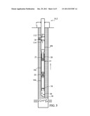
[0020] FIG. 5 is an elevation view, partially in section, of the flow string of FIG. 2 illustrating sludge retained in the flow string;
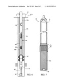
[0021] FIG. 6 is an elevation view, partially in section, of a flow string of a third embodiment of an improved system for cleaning a bottom-hole formation zone of a wellbore, wherein the system further includes a thermochemical cartridge and a packer; and
[0022] FIG. 7 is an enlarged, elevation view of the thermochemical cartridge of FIG. 6.
DESCRIPTIONS OF THE PREFERRED EMBODIMENTS
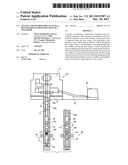
[0023] Referring to the drawings and first to FIG. 1, this shows a first embodiment of an improved system 10.1 for cleaning a bottom-hole zone of a wellbore. The system 10.1 includes a head 12 from which a flow string 14 extends. The flow string 14 includes a plurality of tubing sections 16a, 16b, 16c and 16d. In this example, a proximal end 13 of the flow string includes a first tubing section 16a extending from the head 12 to a drain valve 18. The drain valve 18 is disposed between the first tubing section 16a and a second tubing section 16b. The second tubing section 16b extends between the drain valve 18 and a hydrostatic joint 20. A third tubing section 16c extends between the hydrostatic joint 20 and a throttle 22. A fourth tubing section 16d extends from the throttle 22 towards a distal end 15 of the flow string 14. The system 10.1 is modular and is provided with a first modular section 30 for bottom-hole cleaning and a second modular section 40 for bottom-hole formation zone cleaning. The modular sections 30 and 40 are interchangeable.
[0024] The first modular section 30 includes a check valve 34, wherein the fourth tubing section 16d extends between the throttle 22 and the check valve 34. The first modular section also includes a drill bit 36 for drilling into a plug at the bottom-hole. A nib 38 allows bottom-hole fluid and/or sludge to flow into the flow string 14. The second modular section 40 includes a shielding centralizer 44, wherein the fourth tubing section 16d extends between the throttle 22 and the shielding centralizer 44. The second modular section 40 also includes an edge filter 46 through which fluid and/or sludge may flow into the flow string 14. The shielding centralizer 44 and edge filter 46 also function as containers for retaining fluid and/or sludge flowing into the flow string 14.
[0025] The flow string 14 is preferably in fluid communication with a sump 50. In this example, a conduit 52 extends from the head 12 to sump 50 and maintains the flow string 14 in communication with the sump 50. Fluid and/or sludge can accordingly flow from the bottom-hole zone of a wellbore to the sump 50. This allows the fluid to be disposed of in a safe and environmentally favourable manner. The system as thus far described is similar to the system as described in the applicants' earlier Russian Utility Model RU 84048 which was published on Jun. 27, 2009 and the full disclosure of which is incorporated herein by reference.
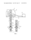
[0026] Referring now to FIG. 2, this shows a second embodiment of an improved system 10.2 for cleaning a bottom-hole zone of a wellbore. The second embodiment of the system 10.2 is substantially similar to the first embodiment of the system 10.1, shown in FIG. 1, together with the first modular section 30 thereof less the drill bit 36 and further including a filter 39. Accordingly, in FIG. 2 like parts have been given like reference numeral as in FIG. 1. As shown in FIG. 2, the head 12 is preferably also in fluid communication with a fluid reservoir 54. The fluid may be water. The fluid is discharged or pumped from the reservoir 54 into the wellbore around the flow string. This causes a pressure differential which results in bottom-hole fluids and/or sludge flowing up the flow string 14 as will be discussed in greater detail below.
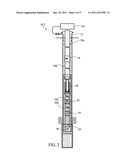
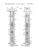
[0027] Operation of the second embodiment of the system 10.2 is shown in FIGS. 3 to 5. As best shown in FIG. 3, the hydrostatic joint 20 includes a valve 21 which is closed as the flow string 14 is lowered into the wellbore. This maintains an air pocket in the third and fourth tubing sections 16c and 16d. When the flow string 14 is in position, a fluid, water in this example, is discharged or pumped into the wellbore as indicated generally by arrows 102, 104 and 106. This causes a hydrostatic pressure differential between the flow string 14 and the wellbore. When the valve 21 of the hydrostatic joint 20 is opened, bottom-hole fluids and/or sludge flow into the flow string 14. This is best shown in FIG. 4. The filter 39 restricts the flow of bottom-hole fluids and/or sludge into the flow string 14 and the check valve 34 prevents backwash from the flow string 14. The throttle 22 controls the speed of fluid and/or sludge flow towards the hydrostatic joint 20.
[0028] The fluid discharged into the wellbore is initially allowed to flow through and out of the flow string 14 to the sump 50 (shown in FIG. 1) as generally indicated by arrows 108 and 110 in FIG. 4. This contributes to lowering of the fluid level in the wellbore as sludge, sand in this example, fills the third and fourth sections of tubing 16c and 16d. As shown in FIG. 5, when the third and fourth sections of tubing 16c and 16d are filled with sludge and the valve 21 of the hydrostatic joint 20 is closed, fluid in the first and second sections of tubing 16a and 16b flows out the drain valve 18 and refills the wellbore. The flow sting is then extracted from the wellbore with the sludge retained in the third and fourth sections of tubing 16c and 16d. The sludge may then be disposed of in a safe and environmentally friendly manner.
[0029] It will be understood by a person skilled in the art that the first embodiment of the system 10.1 together with its first modular section 30 operates in a similar manner. The first embodiment of the system 10.1 together its with the second modular section 40 also operates in similar manner with the exception that fluid and/or sludge flow into the flow string 14 through the edge filter 46. Fluid and/or sludge may also be retained in the shielding centralizer 44 and edge filter 46.
[0030] Referring now to FIG. 6, this shows a third embodiment of an improved system 10.3 for cleaning a bottom-hole zone of a wellbore. The third embodiment of the system 10.3 is substantially similar to the second embodiment of the system 10.2, shown in FIG. 2, and in FIG. 3 like parts has been given like reference numeral as in FIG. 2. However, the third embodiment of the system 10.3 is further provided with a thermochemical cartridge 60 and a packer 62 which may be an inflatable bladder. In this example, the thermochemical cartridge 60 is disposed adjacent a distal end 15 of the flow string 14 and is coupled to the flow string by an elongate member 64. The packer 62 is disposed about fourth tubing section 16d but may disposed anywhere along the flow string 14. The packer 62 functions to seal the bottom-hole formation zone of the wellbore, thereby containing hydrochloric and hydrofluoric acids produced by the thermochemical cartridge 60 at the bottom-hole formation zone of the wellbore.
[0031] The thermochemical cartridge 60 is shown in greater detail in FIG. 7 and includes a pressurized chamber 72 which is separated from a composite material 74 by a combustible diaphragm 76. In this example, a portion of the thermochemical cartridge 60 containing the composite material 74 is received in a sieved receptacle 78. The composite material 74 generates hydrochloric acid or a mixture of hydrochloric acid and hydrofluoric acid when combusted, and should not be explosive. An electrical pulse is fed by a wire (not shown) to a fuse 80 which ignites the composite material 74. Combustion of the composite material 74 eventually causes the combustible diaphragm 76 to combust and the pressurized chamber 72 to implode.
[0032] Providing the system 10.3 with the thermochemical cartridge 60 is desirable because the high temperatures resulting from the combustion of the composite material 74 increase the pressure of the bottom-hole formation zone of the wellbore. This causes gases to penetrate into the formation and melt resinous sediments. In particular, the hydrochloric acid and hydrofluoric acid generated by the combustion of composite material 74 are in a vaporous state and react with the formation to increase the porousness and penetrability of the formation. Furthermore, when the pressurized chamber 72 of the thermochemical cartridge 60 implodes there is a sudden drop in pressure in the bottom-hole formation zone of the wellbore. This causes the melted resinous sediments to be drawn out of the formation. The melted resinous sediments may then be extracted from the bottom-hole formation zone of the wellbore by the system 10.3 using a hydrostatic pressure differential as described above.
[0033] It will be understood by a person skilled in the art that although the system as described herein is used to clean a bottom-hole formation zone of a wellbore, the system may be used to clean any zone along a length of the wellbore.
[0034] It will further be understood by a person skilled in the art that many of the details provided above are by way of example only, and are not intended to limit the scope of the invention which is to be determined with reference to following claims.
User Contributions:
Comment about this patent or add new information about this topic:
Images included with this patent application:
 |  |
 |  |
 |  |
| Similar patent applications: | |
| Date | Title |
|---|---|
| 2010-05-13 | Casing annulus tester for diagnostics and testing of a wellbore |
| 2010-10-07 | Injection of treatment materials into a geological formation surrounding a well bore |
| 2009-10-22 | System and method for controlling placement and flow at multiple gravel pack zones in a wellbore |
| 2008-09-04 | System and method for stimulating multiple production zones in a wellbore |
| 2011-05-12 | Method of treating bottom-hole formation zone |
| New patent applications in this class: | |
| Date | Title |
|---|---|
| 2017-08-17 | Wellbore reverse circulation with flow-activated motor |
| 2016-07-07 | Acid block and method of local acid treatment of subsea connecting element |
| 2016-05-26 | Downhole cleaning tool and cleaning method |
| 2016-05-19 | Apparatus and method for cultivating a downhole surface |
| 2016-05-12 | Mainbore clean out tool |
| Top Inventors for class "Wells" | |
| Rank | Inventor's name |
|---|---|
| 1 | Michael L. Fripp |
| 2 | Jean Marc Lopez |
| 3 | Michael H. Johnson |
| 4 | Jørgen Hallundbaek |
| 5 | Dennis P. Nguyen |