Patent application title: PORTABLE TERMINAL DEVICE AND KEY ARRANGEMENT CONTROL METHOD
Inventors:
Tomohiro Hiramoto (Tokyo, JP)
IPC8 Class: AG09G500FI
USPC Class:
345156
Class name: Computer graphics processing and selective visual display systems display peripheral interface input device
Publication date: 2011-09-29
Patent application number: 20110234487
Abstract:
A hold position detection unit for detecting a position held by an
operator's hand is provided in at least both side portions of a terminal
main body. And a display screen of a key group displayed on an operation
display part is changed based on hold data indicating the position held
by the operator's hand that is detected by the hold position detection
unit.Claims:
1-9. (canceled)
10. A portable terminal device, comprising: a hold position detection unit which provide in a terminal main body for detecting a position held by an operator's hand; an operation display part which display a key group operated by the operator, and a display control part which changes a display screen of the key group displayed on the operation display part based on hold data indicating the position held by the operator's hand that is detected by the hold position detection unit.
11. A portable terminal device according to claim 10, wherein the display control part determines whether the operator holds it with the right hand or the left hand based on the hold data of the operator that is detected by the hold position detection unit and changes a display position and a size of the key group displayed on the operation display part based on the determination result.
12. A portable terminal device according to claim 10, wherein the display control part determines whether the operator holds it with the right hand and whether the operator holds it with the left hand based on the hold data of the operator that is detected by the hold position detection unit and changes the display position of the key group displayed on the operation display part to right or left so as to facilitate operation of the keys based on the determination result.
13. A portable terminal device according to claim 10, wherein the hold position detection unit is provided in not only both side portions of the terminal main body but also a rear portion of the terminal main body.
14. A portable terminal device according to claim 10, further comprising a camera which is arranged at a rear surface of the terminal main body, wherein when the camera is activated, the display control part changes a position of the display screen of the key group that is displayed on the operation display part so that the display screen is located apart from a position of the camera.
15. A key arrangement control method in a portable terminal device which has an operation display part for displaying a key group operated by an operator and in which various processes are performed based on operation of keys on the operation display part, comprising: a procedure for changing a display screen of the key group displayed on the operation display part based on an output from a hold position detection unit provided to a terminal main body for detecting a position held by an operators hand.
16. A key arrangement control method in the portable terminal device according to claim 15, further comprising; a procedure for determining whether the operator holds it with a right hand or a left based on hold data of the operator that is detected by the hold position detection unit and changing a display position and a size of the key group displayed on the operation display part based on the determination result.
17. A key arrangement control method in the portable terminal device according to claim 15, wherein the hold position detection unit is provided in not only both side portions of a terminal main body but also a rear portion of the terminal main body.
18. A key arrangement control method in the portable terminal device according to claim 15, further comprising; a procedure for changing a position of the display screen of the key group displayed on the operation display part so that the display screen is located apart from a position of a camera when the camera arranged at a rear surface of the terminal main body is activated.
Description:
TECHNICAL FIELD
[0001] The present invention relates to a portable terminal device in which a key arrangement can be flexibly changed and determined according to a hold position at which a user holds a terminal main body and a key arrangement control method.
BACKGROUND ART
[0002] So far, as this kind of technology of the key arrangement for a portable terminal device, a portable terminal device described in Japanese Patent Application Laid-Open No. 2008-84144 is known.
[0003] In the portable terminal device described in Japanese Patent Application Laid-Open No. 2008-84144, a display part detects a continuously moving input using a touch panel that starts from one point in a display area of an operation key group displayed on the display part. After the detection, the one point corresponding to the starting point is designated as a fixed point, the starting point is moved according to the continuously moving input, and also, the display area of the operation key group is enlarged or reduced according to the movement of the starting point.
[0004] At the same time, a layout of the operation key group is changed by enlarging or reducing at least a part of the operation key group.
[0005] [PATENT DOCUMENT 1] Japanese Patent Application Laid-Open No. 2008-84144.
DISCLOSURE OF INVENTION
Problems to be Solved by the Invention
[0006] In the portable terminal device described in the above-mentioned Japanese Patent Application Laid-Open No. 2008-84144, a change in size such as enlargement or reduction of the display area of the operation key group can be achieved according to a data input status on the touch panel by an operator and whereby operability of a key can be improved.
[0007] However, in such portable terminal device, the change in size of the operation key group can be achieved by operating the operation key group on the touch panel or performing an additional operation such as drag operation by the operator step by step. Therefore, there is a problem on operability.
[0008] The present invention is made in view of the above-mentioned situation and provides a portable terminal device in which an operation key group can be quickly and easily changed without performing an additional operation by an operator and a key arrangement control method.
Means for Solving the Problems
[0009] In order to solve the above-mentioned problem, a portable terminal device include a hold position detection unit which provide in a terminal main body for detecting a position held by an operator's hand, an operation display part which display a key group operated by the operator, and a display control part which changes a display screen of the key group displayed on the operation display part based on hold data indicating the position held by the operator's hand that is detected by the hold position detection unit.
[0010] A key arrangement control method in a portable terminal device which has an operation display part for displaying a key group operated by an operator and in which various processes are performed based on operation of keys on the operation display part include a procedure for changing a display screen of the key group displayed on the operation display part based on an output from a hold position detection unit provided to a terminal main body for detecting a position held by an operator's hand.
Advantages of the Invention
[0011] In this invention, a hold position detection unit for detecting the position held by the operator's hand is provided on both side portions of the terminal main body and the display screen of the key group displayed on the operation display part is changed based on the hold data indicating the position held by the operator's hand that is detected by the hold position detection unit.
[0012] Therefore, the change in display screen indicating the operation key group can be automatically and correctly performed without performing the additional operation by the operator.
BRIEF DESCRIPTION OF THE DRAWINGS
[0013] FIG. 1 is an external view of a wireless portable terminal 100 of a first exemplary embodiment according to the present invention, FIG. 1A is a left side view, FIG. 1B is a front view, FIG. 1C is a right side view, and FIG. 1D is a rear view.
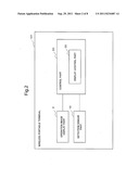
[0014] FIG. 2 is a block diagram showing a control device 101 of the wireless portable terminal 100.
[0015] FIG. 3 is an external view of a wireless portable terminal 300 of a second exemplary embodiment according to the present invention, FIG. 3A is a left side view, FIG. 3B is a front view, FIG. 3C is a right side view, and FIG. 3D is a rear view.
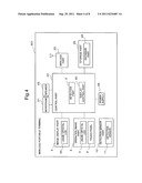
[0016] FIG. 4 is a block diagram showing a control device 301 of the wireless portable terminal 300.
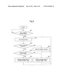
[0017] FIG. 5 is a flowchart showing a control procedure of a display control part 30.
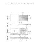
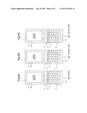
[0018] FIG. 6 is a view showing a screen display of an operation display part 2, FIG. 6A shows a normal screen, FIG. 6B shows a screen for right hand, and FIG. 6C shows a screen for left hand.
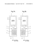
[0019] FIG. 7 is a view showing a screen display of the operation display part 2, FIG. 7A shows a screen for right hand of an operator with a small hand, and FIG. 7B shows a screen for left hand of an operator with a small hand.
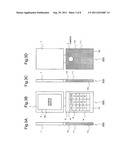
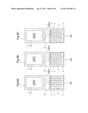
[0020] FIG. 8 is a view showing a screen display of the operation display part 2 when a camera 7 is activated, FIG. 8A shows a normal screen, FIG. 8B shows a screen for right hand, and FIG. 8C shows a screen for left hand.
BEST MODE FOR CARRYING OUT THE INVENTION
[0021] An exemplary embodiment according to a portable terminal device and a key arrangement control method of the present invention will be described with reference to FIG. 1 to FIG. 8.
First Exemplary embodiment
[0022] First, a first exemplary embodiment according to the present invention will be described. FIG. 1 is an external view of a wireless portable terminal 100 of the first exemplary embodiment according to the present invention, FIG. 1A is a left side view, FIG. 1B is a front view, FIG. 1C is a right side view, and FIG. 1D is a rear view.
[0023] In these figures, an operation display part 2 and a screen display part 3 are provided in a front portion 1A of a terminal main body indicated with a symbol of "1".
[0024] The operation display part 2 is input means having a key group 5 in which keys arc arranged on a liquid crystal display 4 in a matrix shape and specifically, it is composed of a touch panel 6 which receives an input from the key group 5 in conjunction with the liquid crystal display 4.
[0025] The screen display part 3 displays the input data from the key group 5 of the operation display part 2 and also it is composed of a liquid crystal display 3A for displaying various modes.
[0026] Additionally, a hold position detection unit 10 for detecting the position held by the operator's hand is provided in both side portions 1C (refer to FIG. 1A and FIG. 1C) and a rear portion 1B (refer to FIG. 1D) of the terminal main body 1.
[0027] This hold position detection unit 10 is composed of a touch sensor 11. An area in which the operator holds the touch sensor 11 becomes an ON-state and an area in which the operator docs not hold the touch sensor 11 becomes an OFF-state.
[0028] A control part 20 (described later) determines a size of the operator's hand and whether the terminal main body 1 is held with a right hand/whether it is held with a left hand based on the ON/OFF area detected by the touch sensor 11.
[0029] Here, the touch sensor is a sensor for determining whether or not the operator touches both side portions and the rear portion of the terminal main body.
[0030] FIG. 2 is a block diagram showing a control device 101 of the wireless portable terminal 100. An operation image display part 2 and a detection sensor part 10 including the hold position detection unit arc connected to the control part indicated with a symbol of "20".
[0031] The control part 20 includes a display control part 30 of a key arrangement control device according to the present invention and the display control part 30 performs a process for changing a display position and a size of the key group 5 on the operation display part 2 based on the output from the detection sensor part 10 for detecting the position held by the operator's hand.
[0032] As described in detail above, in the wireless portable terminal 100 shown in this exemplary embodiment, the hold position detection unit for detecting the position held by the operator's hand is provided in both side portions of the terminal main body and the display screen of the key group displayed on the operation display part is changed based on the hold data indicating the position held by the operator's hand that is detected by the hold position detection unit.
[0033] Therefore, the change of the display screen displaying the operation key group can be automatically and correctly performed without performing the additional operation by the operator.
The Second Exemplary Embodiment
[0034] Next, a second exemplary embodiment according to the present invention will be described.
[0035] FIG. 3 is an external view of a wireless portable terminal 200 of the second exemplary embodiment according to the present invention, FIG. 3A is a left side view, FIG. 3B is a front view, FIG. 3C is a right side view, and FIG. 3D is a rear view.
[0036] In these figures, the operation display part 2 and the screen display part 3 are provided in the front portion 1A of the terminal main body indicated with a symbol of "1".
[0037] The operation display part 2 is input means having the key group 5 in which keys arc arranged on the liquid crystal display 4 in a matrix shape and specifically, it is composed of the touch panel 6 which receives an input from the key group 5 in conjunction with the liquid crystal display 4.
[0038] The screen display part 3 displays input data from the key group 5 of the operation display part 2 and also it is composed of the liquid crystal display 3A for displaying various modes.
[0039] Meanwhile, a camera 7 shown in FIG. 3D is provided in the rear portion 1B of the terminal main body 1.
[0040] This camera 7 is located at the back side of the operation display part 2, and activated and stopped by an instruction from the key group 5 of the operation display part 2.
[0041] The hold position detection unit 10 for detecting the position held by the operator's hand is provided in both side portions 1C (refer to FIG. 3A and FIG. 3C) and the rear portion 1B (refer to FIG. 3D) of the terminal main body 1.
[0042] This hold position detection unit 10 is composed of the touch sensor 11. An area in which the operator holds the touch sensor 11 becomes an ON-state and an area in which the operator does not hold the touch sensor 11 becomes an OFF-state.
[0043] The control part 20 determines a size of the operator's hand and whether the terminal main body 1 is held with a right hand/whether it is held with a left hand based on the ON/OFF area detected by the touch sensor 11.
[0044] FIG. 4 is a block diagram showing a control device 301 of a wireless portable terminal 300. The operation display part 2, the screen display part 3, the hold position detection unit 10, a microphone 21, a speaker 22, a wireless part 23 for performing communication, a storage part 25 including a database part 24, a power supply 26, and the like arc connected to the control part indicated with a symbol of "20".
[0045] The control part 20 includes the display control part 30 of the key arrangement control device according to the present invention and in the display control part 30, a process for changing the display position and the size of the key group 5 on the operation display part 2 is performed based on the output from the hold position detection unit 10 for detecting the position held by the operator's hand.
[0046] The control procedure of this display control part 30 will be described with reference to FIG. 5.
[0047] Further, the process shown in FIG. 5 and the display screen for various modes that is displayed on the operation display part 2 are stored in the database part 24 of the storage part 25 in advance.
[0048] First, in step 1 (SP1), in the operation display part 2, it is determined whether a "normal screen mode" in which the position and the size of the display screen arc not changed is selected and whether a "screen change mode" in which the position and the size of the display screen are changed is selected. When the "screen change mode" is selected, namely, the decision in step 1 is "Yes", the process advances to next step 2.
[0049] Further, the selection of the "normal screen mode" or the "screen change mode" is performed in a mode selection screen displayed on the operation display part 2.
[0050] Next, in step 2 (SP2), the hold data which indicates the ON state when the operator holds the touch sensor 11 and the OFF state when the operator does not hold it is fetched from the hold position detection unit 10.
[0051] In next step 3 (SP3), it is determined whether or not the operator holds the wireless portable terminal 100 at present by fetching the hold data in step 2. In case of the NO state in which the operator docs not hold the touch sensor 11, the process advances to next step 4 (SP4) and in case of the YES state in which the operator holds the touch sensor 11, the process advances to next step 5 (SP5).
[0052] In Step 4, it is determined that the wireless portable terminal 300 has not yet been held by the operator and the screen displayed on the operation display part 2 is set to a normal screen which is the same as that in the "normal screen mode" shown in FIG. 6A and whose position and size are not changed.
[0053] In step 5 (SP5), it is determined whether the touch sensor 11 is held with the operator's right hand and whether the touch sensor 11 is held with the operator's left hand based on ON/OFF data indicated by the hold data fetched in step 2. When the touch sensor 11 is held with the operator's right hand, the process advances to step 6 (SP6) and when the touch sensor 11 is held with the operator's left hand, the process advances to step 7 (SP7).
[0054] Further, in this step 5 (SP5), when the ON area of the touch sensor 11 located in the right side portion 1C is greater than the ON area of the touch sensor 11 located in the left side portion 1C among the touch sensors 11 (the hold position detection unit 10) that are provided in both side portions 1C of the terminal main body 1, it is determined that the operator holds the touch sensor 11 with the right hand and when the ON area of a touch sensor 1 located in the left side portion 1C is greater than the ON area of the touch sensor 11 located in the right side portion 1C, it is determined that the operator holds the touch sensor 11 with the left hand.
[0055] As a criterion for determining whether the operator holds it with the right hand and whether the operator holds it with the left hand, a criterion in which a plurality of hold patterns when the touch sensor 11 is held with the left hand and the right hand arc prepared in advance and it is determined whether the operator holds it with the right hand and whether the operator holds it with the left based on the coincidence between the pattern obtained by using the touch sensor 11 located in both side portions IC and/or the rear portion 1B and these prepared hold patterns may be used instead of the above-mentioned criterion in which the determination is performed based on the magnitude relation between the ON area of the touch sensor 11 located in one of the side portions 1C and the ON area of the touch sensor 11 located in the other of the side portions 1C.
[0056] In step 6 (SP6), a display screen for right hand shown in FIG. 6B that is stored in advance is displayed on the operation display part 2 based on the result determined in step 5.
[0057] The display screen for right hand is placed in the right side of the operation display par 2 although the normal screen is placed in the center position that is a reference position (refer to FIG. 6A) in order to facilitate the operation of keys with the right hand in the operation display part 2.
[0058] Additionally, when it is determined that a range of the ON area of the touch sensor 11 held with the operator's right hand that is located in the (right) side portion 1C and a range of the ON area of the touch sensor 11 held with the operator's right hand that is located in the rear portion 1B are smaller than a predetermined and specified range based on the hold data fetched in step 2, the display screen is changed to a display screen for right hand shown in FIG. 7A that is smaller than the display screen shown in FIG. 6B.
[0059] In step 7 (SP7), the display screen for left hand as shown in FIG. 6C. that is stored in advance is displayed on the operation display part 2 based on the result determined in step 5.
[0060] The display screen for left hand is placed in the left side of the operation display part 2 although the normal screen is placed in the center position that is the reference position (refer to FIG. 6A) in order to facilitate the operation of keys with the left hand in the operation display part 2.
[0061] Additionally, when it is determined that the range of the ON area of the touch sensor 11 held with the operator's left hand that is located in the (left) side portion 1C and the range of the ON area of the touch sensor 11 held with the operator's left hand that is located in the rear portion 1B are smaller than the predetermined and specified range based on the hold data fetched in step 2, the display screen is changed to a display screen for left hand shown in FIG. 7B that is smaller than the display screen shown in FIG. 6C.
[0062] Further, when the camera 7 is activated, as shown in FIG. 7A to FIG. 7C, it is desirable that the display screen of the operation display part 2 is placed in a position lower than an embedded position 7A at which the camera 7 placed in the rear portion 1B of the terminal main body 1 is embedded so that the display screen is located apart from the embedded position 7A.
[0063] Namely, in case of the normal screen shown in FIG. 6A, the normal screen is displayed as shown in FIG. 8A. In case of the display screen for right hand shown in FIG. 6B, the display screen for right hand is displayed as shown in FIG. 8B. In case of the display screen for left hand shown in FIG. 6C, the display screen for left hand is displayed as shown in FIG. 8C.
[0064] By performing such changes in screen display, the wireless portable terminal 100 with which a photograph can be taken without a trouble in which the camera 7 is covered with the operator's hand when the operator operates the key group 5 and which has good operability can be obtained.
[0065] As described in detail above, in the wireless portable terminal 300 described in the exemplary embodiment, the hold position detection unit 10 for detecting the position held by the operator's hand is provided in both side portions 1C and the rear portion 1B of the terminal main body 1 and the display screen of the key group 5 displayed on the operation display part 2 is changed based on the hold data indicating the position held by the operator's hand that is detected by the hold position detection unit 10.
[0066] By the hold position detection unit 10 provided in at least both side portions of the terminal main body 1 for detecting the position held by the operator's hand, the situation in which the operator holds the portable terminal, such as whether the operator's hand is small, whether the terminal main body 1 is held with a right hand/whether the terminal main body 1 is held with a left hand, and the like, can be grasped correctly.
[0067] As a result, the display screen displaying the key group 5 can be automatically and correctly changed without operating the key group 5 on the touch panel 6 or performing an additional operation such as drag or the like by the operator step by step.
[0068] Additionally, in the above-mentioned wireless portable terminal 300, the camera 7 is arranged on the rear surface of the terminal main body 1. When the camera 7 is activated, the position of the display screen of the key group 5 that is displayed on the operation display part 2 is changed so that the display screen is located apart from the position of the camera.
[0069] Consequently, a photograph can be taken without a trouble in which the camera is covered with the operator's hand when the operator operates the key group 5 and operability of the wireless portable terminal can be improved in this respect.
[0070] Further, in the above-mentioned exemplary embodiment, one small-sized display screen for right hand shown in FIG. 7A and one small-sized display screen for left hand shown FIG. 7B are prepared. However, a method in which a plurality of display screens are stored according to the size of the operator's hand in advance and the display screen is changed in a multistage manner according to the range of the ON area of the touch sensor 11 held by the operator may be used.
[0071] Furthermore, a configuration in which according to the situation, the display screen is changed only from the normal screen shown in FIG. 6A to the display screen for right hand shown in FIG. 6B or the display screen for left hand shown in FIG. 6C and it is not changed to the small-sized display screen as shown in FIG. 7A and FIG. 7B may be used.
[0072] In order to precisely detect a state held by the operator, the touch sensor 11 of the hold position detection unit 10 is provided in both side portions 1C and the rear portion 1B of the terminal main body 1. However, it is not essential to provide the touch sensor 11 in the rear portion 1B of the terminal main body 1 for detecting whether the operator holds it with the right hand, whether the operator holds it with the left, and whether or not the operator' hand is small and it may be arbitrarily deleted.
[0073] The exemplary embodiment of the present invention has been described in detail above with reference to the drawings. However, a specific configuration is not limited to this exemplary embodiment and design change or the like can be made without departing from the gist of the present invention.
[0074] This application insists on priority based on Japanese Patent Application No. 2008-319604 filed on Dec. 16, 2008 and the disclosure of which is hereby incorporated in its entirety.
INDUSTRIAL APPLICABILITY
[0075] The present invention can be applied to a portable terminal and a portable device in which operation is performed by using a touch panel.
[0076] Description of Symbol
[0077] 1 terminal main body
[0078] 1C side portion
[0079] 2 operation display part
[0080] 5 key group
[0081] 7 camera
[0082] 10 hold position detection unit
[0083] 30 display control part
[0084] 100, 200, 300 wireless portable terminal
User Contributions:
Comment about this patent or add new information about this topic:
| People who visited this patent also read: | |
| Patent application number | Title |
|---|---|
| 20220261875 | ARTIFICIAL INTELLIGENCE BASED PRODUCT RECOMMENDATION METHODS AND SYSTEMS FOR ENHANCING APPROVALS OF PAYMENT PROCESSING REQUESTS |
| 20220261874 | NON-TRANSITORY COMPUTER READABLE MEDIUM STORING EVENT PROVISION PROGRAM AND EVENT PROVISION SYSTEM |
| 20220261873 | AUTOMATICALLY GENERATING SIMILAR ITEMS USING SPECTRAL FILTERING |
| 20220261872 | METHODS AND APPARATUS TO TRANSLATE AND MANAGE PRODUCT DATA |
| 20220261871 | SIZE COMPARISON SYSTEMS AND METHODS INCLUDING ONLINE COMMERCE EXAMPLES UTILIZING SAME |
Images included with this patent application:
 |  |
 |  |
 |  |
 |  |
| New patent applications in this class: | |
| Date | Title |
|---|---|
| 2022-05-05 | Electrode structure combined with antenna and display device including the same |
| 2022-05-05 | Conductive bonding structure for substrates and display device including the same |
| 2022-05-05 | Electronic product and touch-sensing display module thereof including slot in bending portion of film sensing structure |
| 2022-05-05 | Multi-modal hand location and orientation for avatar movement |
| 2022-05-05 | Method and apparatus for controlling onboard system |
| New patent applications from these inventors: | |
| Date | Title |
|---|---|
| 2012-12-20 | Portable information terminal and key arrangement alteration method therefor |
| Top Inventors for class "Computer graphics processing and selective visual display systems" | |
| Rank | Inventor's name |
|---|---|
| 1 | Katsuhide Uchino |
| 2 | Junichi Yamashita |
| 3 | Tetsuro Yamamoto |
| 4 | Shunpei Yamazaki |
| 5 | Hajime Kimura |