Patent application title: METHOD TO INCREASE GAS MASS FLOW INJECTION RATES TO GAS STORAGE CAVERNS USING LNG
Inventors:
Jose Lourenco (Edmonton, CA)
Mackenzie Millar (Edmonton, CA)
IPC8 Class: AF28D1500FI
USPC Class:
16510419
Class name: Heat exchange intermediate fluent heat exchange material receiving and discharging heat liquid fluent heat exchange material
Publication date: 2011-09-08
Patent application number: 20110214839
Abstract:
A method to increase gas mass flow loading rates to a gas storage cavern
includes using liquid natural gas (LNG) to cool natural gas in a natural
gas flow line upstream of a compressor used to compress gas for storage
in to a gas storage cavern.Claims:
1. A method to increase gas mass flow injection rates to a gas storage
cavern, comprising: using liquid natural gas (LNG) to cool natural gas in
a natural gas flow line upstream of a compressor used to compress gas for
storage in to a gas storage cavern.
2. The method of claim 1, including a step of effecting a heat exchange between the natural gas in the gas flow line upstream of the compressor and LNG passing through a heat exchanger.
3. The method of claim 1, including a step of using LNG to cool natural gas in the natural gas flow line downstream of a compressor prior to the compressed natural gas entering the gas storage cavern.
4. The method of claim 3, including a step of injecting LNG into the natural gas flow line downstream of the compressor.
5. The method of claim 3, including a step of effecting a heat exchange between the natural gas in the gas flow line downstream of the compressor and LNG passing through a heat exchanger.
6. The method of claim 1, including a step of performing direct injection of LNG into the gas storage cavern.
7. The method of claim 4, including a step of monitoring a temperature of the gas storage cavern and controlling the injection of LNG into the natural gas flow line downstream of the compressor based upon the temperature of the gas storage cavern.
8. A method to increase gas mass flow injection rates to a gas storage cavern, comprising: effecting a heat exchange between the natural gas in a natural gas flow line upstream of a compressor used to compress gas for storage in to a gas storage cavern and liquid natural gas (LNG) passing through an upstream heat exchanger to cool natural gas in the natural gas flow line upstream of a compressor used to compress gas for storage in to a gas storage cavern; and injecting LNG that has passed through the upstream heat exchanger into one of the natural gas flow line downstream of the compressor or into the gas storage cavern.
9. The method of claim 8, including a step of effecting a heat exchange between the natural gas in the gas flow line downstream of the compressor and LNG passing through a downstream heat exchanger.
10. The method of claim 8, including a step of monitoring a temperature of the gas storage cavern and performing injection of LNG into one of the natural gas storage flow line downstream of the compressor or the gas storage cavern, as required to maintain the gas storage cavern at a preselected temperature.
Description:
FIELD
[0001] The present invention relates to a method of increasing gas mass flow injection rates to gas storage caverns using LNG.
BACKGROUND
[0002] Natural gas is traditionally stored in a gaseous form in large volume salt caverns and aquifers to meet peak demand and ensure a secure supply. The gas is added to storage by compression, resulting in an increment in cavern temperature and an increment in cavern pressure. These increments in pressure and temperature in the cavern decrease the rate at which gas can be added to the cavern.
SUMMARY
[0003] A method to increase gas mass flow injection rates to a gas storage cavern, includes using liquid natural gas (LNG) to cool natural gas in a natural gas flow line upstream of a compressor used to compress gas for storage in to a gas storage cavern.
BRIEF DESCRIPTION OF THE DRAWINGS
[0004] These and other features of the invention will become more apparent from the following description in which reference is made to the appended drawings, the drawings are for the purpose of illustration only and are not intended to in any way limit the scope of the invention to the particular embodiment or embodiments shown, wherein:
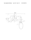
[0005] FIG. 1 is a schematic diagram that depicts an embodiment of the teachings contained herein.
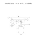
[0006] FIG. 2 is a variation on the embodiment shown in FIG. 1.
DETAILED DESCRIPTION
[0007] The preferred method to increase mass flow gas injection rates will now be described with reference to FIG. 1.
[0008] Gas is supplied from main pipeline stream 1. The gas to storage is routed through line 2 to exchanger 30 where it is cooled by LNG. The cooler gas exits exchanger 30 via stream 3 to knock out drum 31, to remove any condensate and debris present in the stream. The condensate is removed through stream 4. The cold gas is routed through stream 5 to compressor 32 for injection into cavern 33 via stream 6. LNG is supplied from tank 35 and is routed through line 8 to pump 36 where it is pressurized and routed through line 9. The LNG is routed through line 10 to exchanger 30, to cool the gas to storage and exits the exchanger through line 11. The gas in stream 11 is colder than compressed gas in stream 6. The gas can then be routed through valve 39 and line 12 to mix directly with stream 6 in mixer 41, increasing the gas density of gas stream 7 to storage 33. The option of routing stream 11 through valve 38 and line 13 directly to storage cavern 33 is available. The operating conditions for the cavern are monitored by pressure and temperature sensors 34. The objective is to increase the gas injection rate of compressor 32 by lowering the temperature of the gas suction line to the compressor, making the gas denser, thus increasing the mass flow rate and also decreasing the compressor outlet temperature. The compressor outlet temperature can be further decreased by direct mixing of stream 12 with stream 6. For every incremental decrease in the temperature of gas entering cavern 33, the amount of gas cavern 33 is capable of storing increases. If it is desirable to further decrease the temperature of cavern 33, the option of routing stream 11 through valve 38 and line 13 directly to storage cavern 33 is followed.
[0009] A variation will now be described with reference to FIG. 2.
[0010] Gas is supplied from main pipeline stream 1. The gas to storage is routed through line 2 to exchanger 30 where it is cooled by LNG. The cooler gas exits exchanger 30 via stream 3 to knock out drum 31 to remove any condensate and debris present in the stream. The condensate is removed through stream 4. The cold gas is routed through stream 5 to compressor 32, where it is compressed and delivered through line 6 to exchanger 41 where it is cooled. The compressed and cooled stream 7 mixes with stream 11 and is stored through line 12 into gas cavern storage 33. LNG is supplied from tank 35 and is routed through line 8 to pump 36 where it is pressurized and routed through line 9. The LNG is routed to exchanger 30, to cool the gas to storage and exits the exchanger through line 10. The gas in stream 10 is colder than compressed gas in stream 6. The gas stream 10 enters exchanger 41 to cool the compressor discharge gas. The gas can then be routed through valve 39 to mix directly with stream 7 to storage 33 through line 12. The option of routing stream 11 through valve 38 and line 13 directly to storage cavern 33 is available. The operating conditions for the cavern are monitored by pressure and temperature sensors 34. The objective is to increase the gas mass flow injection rate of compressor 32 by lowering the temperature of the gas suction line to the compressor, making the gas denser, thus increasing the mass flow rate whilst also decreasing the compressor outlet temperature. The compressor outlet temperature is further decreased by indirect mixing of stream 10 with stream 6 thus further improving the power requirements for compression. The described embodiment of FIG. 3 provides the ability for gas cavern operators to increase the mass flow gas injection rates to cavern storage.
[0011] The stored gas exits the cavern via stream 50 to meet demand.
[0012] In this patent document, the word "comprising" is used in its non-limiting sense to mean that items following the word are included, but items not specifically mentioned are not excluded. A reference to an element by the indefinite article "a" does not exclude the possibility that more than one of the element is present, unless the context clearly requires that there be one and only one of the elements.
[0013] It will be apparent to one skilled in the art that modifications may be made to the illustrated embodiments without departing from scope of the Claims.
User Contributions:
Comment about this patent or add new information about this topic:
Images included with this patent application:
 |  |
| New patent applications in this class: | |
| Date | Title |
|---|---|
| 2016-12-29 | Nanofluids containing carbon nanotubes and metal oxide nanoparticle composites with enhanced heat transfer and heat capacity properties |
| 2016-07-07 | An inlet system for a thermal storage vessel |
| 2016-07-07 | Heat exchanger having arcuately and linearly arranged heat exchange tubes |
| 2016-06-23 | Motor stator cooling with dual coolant two-phase heat exchanger |
| 2016-05-26 | Heat exchanger with an adapter unit fixed to an endplate, and associated method of manufacture |
| New patent applications from these inventors: | |
| Date | Title |
|---|---|
| 2020-12-31 | Production of petrochemical feedstocks and products using a fuel cell |
| 2016-03-03 | Method to produce lng |
| 2015-12-31 | Method and apparatus for upgrading heavy oil |
| Top Inventors for class "Heat exchange" | |
| Rank | Inventor's name |
|---|---|
| 1 | Levi A. Campbell |
| 2 | Chun-Chi Chen |
| 3 | Tai-Her Yang |
| 4 | Robert E. Simons |
| 5 | Richard C. Chu |