Patent application title: Plate Cooler for Fluids
Inventors:
Philipp Pustelnik (Wien, AT)
Thomas Euler-Rolle (Wien, AT)
IPC8 Class: AF28F312FI
USPC Class:
165170
Class name: Heat exchange conduit within, or conforming to, panel or wall structure opposed plates or shells
Publication date: 2011-06-16
Patent application number: 20110139418
Abstract:
A plate cooler for fluids, in particular hydraulic oil, having a
parallelepiped-shaped package of plate bodies forming spaced-apart fluid
channels, the air channels being interposed between adjacent plate bodies
and the plate bodies communicate on their ends with fluid channels in a
distributor box and a collection box, which are provided with inlet and
outlet lines. The distributor box and the collection box are each
embodied as an extruded aluminum profile and include a continuous
channel, forming the fluid channel, and a ribbed body, which has lateral
ribs with continuous guide grooves for mounting elements and receiving
slots for the extruded plate body profile. The fluid channels formed by
the plate bodies, via the receiving slots, discharge into a collection
chamber, communicating with the continuous channel, of the ribbed body,
which is in communication with the continuous channel. The continuous
receiving slots for the plate bodies in the distributor box and in the
collection box are configured in circular and conical form, and the
inserted plate bodies are connected thereto in fluid-tight fashion in a
low-temperature adhesive bonding process.Claims:
1-5. (canceled)
6. A plate cooler for fluids, in particular hydraulic oil, having a parallelepiped-shaped package of plate bodies forming spaced-apart fluid channels, the air channels being interposed between adjacent plate bodies and the plate bodies communicate on their ends with fluid channels in a distributor box and a collection box, which are provided with inlet and outlet lines, and wherein the distributor box and the collection box are each embodied as an extruded aluminum profile and include a continuous channel, forming the fluid channel, and a ribbed body, which has lateral ribs with continuous guide grooves for mounting elements and receiving slots for the extruded plate body profile, wherein the fluid channels formed by the plate bodies, via the receiving slots, discharge into a collection chamber, communicating with the continuous channel, of the ribbed body, which is in communication with the continuous channel, and the continuous receiving slots for the plate bodies in the distributor box and in the collection box are configured in circular and conical form, and the inserted plate bodies are connected thereto in fluid-tight fashion in a low-temperature adhesive bonding process.
7. The plate cooler as of claim 6, wherein one end of the distributor box and of the collection box is chamfered, in order to receive adapter bodies for pipeline connections of different orientation.
8. The plate cooler of claim 6, wherein in the fluid channel of the distributor box and of the collection box, threads are formed on the ends for securing functional elements, preferably valves for bypass channels.
9. The plate cooler of claim 6, wherein in the vicinity of the air channels, the ribbed body is provided with spacer ribs for thin plates that form the air channels.
Description:
[0001] The invention relates to a plate cooler for fluids, in particular
hydraulic oil, having a parallelepiped-shaped package of plate bodies
forming spaced-apart fluid channels, in which air channels are interposed
between adjacent plate bodies and the plate bodies communicate on their
ends with fluid channels in a distributor box and a collection box, which
are provided with inlet and outlet lines.
[0002] In a plate cooler of the type defined above, it is already known to make a bypass flow in the cold state possible, by providing bypass channels, parallel to the fluid channels, in the package between the distributor box and the collection box, and in the vicinity of the bypass channels, the distributor box provided on the fluid inflow side is equipped in the vicinity of the bypass channels with a valve, which enables the communication between the distributor box and the bypass channels in the cold state.
[0003] In a hydraulic oil air cooler, it is also known for the hydraulic oil lines, leaving the distributor box and discharging into the collection box, to be formed by platelike extruded profiles of hollow cross section.
[0004] A further known embodiment comprises providing the extruded profiles with integrally formed-on inner ribs. In this way, the cooling surface area for the hydraulic oil is enlarged, and thus the cooling power is increased. For the same reasons, it is especially advantageous if the extruded profiles have a multiple-compartment cross section.
[0005] In the known construction, the platelike extruded profiles are soldered on the ends into openings in the distributor box and in the collection box, which while it is an economical manufacturing method still necessitates soldering in a vacuum or in an inert gas (CAB), which is relatively expensive.
[0006] The object of the invention is to create a plate cooler which can be produced and assembled simply from only a few basic components, in order to further reduce the production costs and increase the number of possible uses of the cooler.
[0007] The cooler of the invention is distinguished in that the distributor box and the collection box are each embodied as an extruded aluminum profile and are provided with a continuous channel, forming the fluid channel, and are also provided with a ribbed body, which has lateral ribs with continuous guide grooves for mounting elements and receiving slots for the extruded plate body profile, which discharge into a collection chamber, communicating with the continuous channel, of the ribbed body, which is in communication with the continuous channel.
[0008] Preferably, the receiving slots for the plate bodies in the distributor box and in the collection box are embodied in circular and conical form, and the inserted plate bodies are connected to them in fluid-tight fashion, preferably by a low-temperature method.
[0009] In another embodiment of the invention, the one end of the distributor box and of the collection box is chamfered, in order to receive adapter bodies for pipeline connections of different orientation.
[0010] Further characteristics of the invention will be described in further detail below in terms of one exemplary embodiment, in conjunction with the drawings. In the drawings:
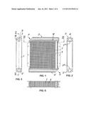
[0011] FIG. 1 is an elevation view of a plate cooler of the invention;
[0012] FIG. 2 is a left side view of the cooler of FIG. 1;
[0013] FIG. 3 is a right side view of the cooler of FIG. 1;
[0014] FIG. 4 shows a detail of FIG. 1 on a larger scale;
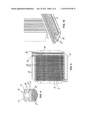
[0015] FIG. 5 is a section along the line V-V in FIG. 3;
[0016] FIG. 6 is a section along the line VI-VI in FIG. 1;
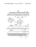
[0017] FIG. 7 is an elevation view of the distributor;
[0018] FIG. 8 is a section along the line VIII-VIII in FIG. 7;
[0019] FIG. 9 is an end view of FIG. 7;
[0020] FIG. 10 is a section along the line X-X in FIG. 9;
[0021] FIG. 11 is an analogous section to FIG. 10, but with oil pipes;
[0022] FIG. 12 is a perspective view of a part of the cooler before assembly; and
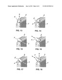
[0023] FIGS. 13-18 are fragmentary views of various adapter connections in perspective.
[0024] The exemplary embodiment shown in FIG. 1 relates to a hydraulic oil cooler, which has a package of parallel plate bodies 1 and air channels 2 comprising air laminations 2' disposed between them, which in the example shown experience a flow through them from top to bottom and which terminate on their ends, beginning at a distributor box 3, in a collection box 3'. The distributor box 3 and the collection box 3' are embodied essentially identically. The plate bodies 1 are embodied as extruded aluminum profiles (for instance in accordance with Austrian Patent 402 235) and are retained in continuous slots 5 of the distributor box 3 and of the collection box 3', as FIG. 12 for instance shows.
[0025] The distributor box 3 and the collection box 3' each also comprise an extruded aluminum profile, which is equipped with an oil channel 6 and a ribbed body 7. The ribbed body, on opposing sides, has guide grooves 8 for receiving mounting elements, such as nuts 12 for bolts (not shown) for securing the cooler or the fan unit in a vehicle, machine, or the like.
[0026] As seen for instance in FIG. 4, the plate bodies 1 each discharge into a vaulted oil collection box 3'', communicating with the associated oil channel 6, of the distributor box 3 or collection box 3'. The thin plates 2' that form air channels each engage end ribs 3''' of the distributor box 3 and collection box 3'. One end each of the distributor box 3 and collection box 3' is chamfered at an angle of 45°, for example, so as to receive adapter bodies F, shown in FIGS. 13-18, for pipeline connections (not shown). The other end of each is closed with a closure screw 9, as FIG. 3 shows.
[0027] The receiving slots 5 for the plate bodies 1 are, as FIG. 12 in particular shows, embodied in circular and conical fashion in the distributor box 3 and the collection box 3'. The joining process for oil-tight connection can be a low-temperature (<300° C.) adhesive bonding process that does not necessitate an inert gas atmosphere or a vacuum. Within the scope of the invention, the plate bodies 1 inserted into the receiving slots 5 can also be soldered to the slots.
[0028] In FIGS. 1 and 5, the oil cooler is equipped with bypass channels 10, known per se, and a valve 11 is screwed into the distributor box 3 via a female thread 13 on the end (for instance as in Austrian Patent 414 042). The valve closure body of the valve 11 can be prestressed into the closing position by a spring, preferably up to a pressure difference of 2-3 bar (opening pressure). This embodiment advantageously makes it possible in normal operation, when the oil is warm and the pressure loss via the plate bodies 1 is low (<2 bar), for the bypass to be closed and for all the oil to flow via the plate bodies 1. If in cold operation the pressure loss in the plate bodies 1 is >2-3 bar, the bypass valve 11 opens and enables the direction communication between the distributor box 3 and the collection box 3' via the bypass channels 10.
[0029] As FIGS. 13-18 show, the adapter body F for pipeline connections can be secured to the oblique face end of the distributor box 3 or collection box 3' with different orientation, without complicated welding, so that all the connection conditions that occur in practice can be properly taken into account. According to the invention, the cooler can experience a flow through it either in the form of a U or diagonally, as indicated for instance by the arrows P.
[0030] It is understood that the invention is not limited to the exemplary embodiments shown; on the contrary, they may be modified in various ways, for instance in terms of how the extruded plate bodies are embodied and how they are connected to the distributor box or the collection box.
User Contributions:
Comment about this patent or add new information about this topic:
Images included with this patent application:
 |  |
 |  |
| New patent applications in this class: | |
| Date | Title |
|---|---|
| 2016-04-21 | A flow distribution module with a patterned cover plate |
| 2016-04-14 | Multi-segmented tube sheet |
| 2016-02-04 | Reduced thermal expansion microchannel coolers |
| 2016-02-04 | Components with micro cooled laser deposited material layer and methods of manufacture |
| 2015-12-10 | Through-plate microchannel transfer devices |
| New patent applications from these inventors: | |
| Date | Title |
|---|---|
| 2018-04-19 | Cooler station for connection of a liquid cooler |
| 2012-07-26 | Plate cooler for fluids |
| 2010-06-03 | Adapter bit for a device for connecting pipe conduits |
| 2009-08-27 | Oil cooler |
| Top Inventors for class "Heat exchange" | |
| Rank | Inventor's name |
|---|---|
| 1 | Levi A. Campbell |
| 2 | Chun-Chi Chen |
| 3 | Tai-Her Yang |
| 4 | Robert E. Simons |
| 5 | Richard C. Chu |