Patent application title: WIND TUNNEL AIRCRAFT MODEL WITH TRUNCATED WING
Inventors:
Esteban Amo Garrido (Madrid, ES)
Pilar Vela Orge (Aranjuez, ES)
Angel Pascual Fuertes (Alcobendas, ES)
Assignees:
AIRBUS Operations S.L.
IPC8 Class: AG06F1750FI
USPC Class:
703 1
Class name: Data processing: structural design, modeling, simulation, and emulation structural design
Publication date: 2011-05-05
Patent application number: 20110106503
or testing in a wind tunnel (11) of width W
comprising a fuselage (21), a truncated wing (25) whose length L1 is
lesser than the length L of a full scaled wing (23) and additional
components in the rear aircraft as, in particular, an horizontal tail
plane (29), that produces the same downwash arriving to said additional
components than in a full scaled model. The shape of said truncated wing
(25) may be designed for having a similar lift distribution (35) to the
lift distribution (37) of a full scaled wing (23) along at least the
maximum length L2 in the Y-axis of any component in the rear aircraft.
The invention also relates to a method for designing said truncated wing
(25).Claims:
1. A method for designing a truncated wing (25) with respect to a full
scaled reference wing (23) for an aircraft model (17) whose configuration
also comprises a fuselage (21) and additional components in the rear
aircraft for performing flow investigations around said additional
components in a wind tunnel (11) of width W, characterized by comprising
the following steps: a) obtaining the initial lift distribution In
and the additional lift distribution an in the reference wing (23);
b) defining the length L1 of the truncated wing (25) in the Y-axis; c)
obtaining the truncated wing (25) chord distribution reconstructing the
additional lift distribution an in the reference wing (23) along the
truncated wing (25); d) obtaining the truncated wing (25) twist
distribution reconstructing the initial lift distribution In in the
reference wing (23) along the truncated wing (25); e) keeping the
profiles, the leading edge geometry and the relative thickness
distribution of the reference wing (23) in the truncated wing (25).
2. A method for designing a truncated wing (25) according to claim 1, characterized in that its length L1 is lesser than the 75% of the wind tunnel width W.
3. A method for designing a truncated wing (25) according to claim 1, characterized in that said components in the rear aircraft include an horizontal tail plane (29).
4. An aircraft model (17) for testing in a wind tunnel (11) of width W, whose configuration comprises a fuselage (21), a wing and additional components in the rear aircraft of a maximum length L2 in the Y-axis, characterized in that it is a full scaled model with the exception that it has a truncated wing (25), whose length L1 is lesser than the length L of a full scaled wing (23) but producing the same downwash in said additional components.
5. An aircraft model (17) according to claim 4, characterized in that the full scaled wing (23) and the truncated wing (25) have similar lift profiles (37, 35) along at least the maximum length L2 in the Y-axis of any component in the rear aircraft.
6. An aircraft model (17) according to any of claims 4-5, characterized in that said rear aircraft components include an horizontal tail plane (29).Description:
FIELD OF THE INVENTION
[0001] The present invention refers to aircraft scaled models used in wind tunnels for analysing its aerodynamic properties and more particularly to aircraft scaled models for analysing the aerodynamic properties of the aircraft tails and rear fuselage.
BACKGROUND OF THE INVENTION
[0002] The performance of aircraft mobile surfaces such as vertical tails, horizontal tail planes, elevators or rudders placed in the rear part of the aircraft is one of the more important issues in global aircraft design. Said surfaces are used as control surfaces, for example a horizontal tail plane is used to control pitch and a rudder is used to control yaw. Therefore its behavior defines aircraft control laws and design constrains.
[0003] When designing the elements composing an aircraft, such as the fuselage, wings, stabilizers, etc. it is necessary to know the aerodynamic properties of such components. In view of the large size of aircrafts, aerodynamic tests are made with scaled models that reproduce the whole or at least a part of the aircraft, the scaled models being subjected to tests in a wind tunnel.
[0004] Those tests are particularly important for the rear part of the aircraft because it is difficult to obtain comprehensive analytical models of its aerodynamic behaviour since the rear part of the aircraft is affected by other parts of an aircraft and particularly by the aircraft wing. For example they can suffer a loss of upstream dynamic pressure due to effects caused by the wing which is difficult to take into account using classical analytical schemes.
[0005] Even though the results currently obtained in wind tunnel tests allow a good understanding of the aerodynamical behaviour of tails and other components of the rear part of the aircraft, they are usually produced at a Reynolds number very much lower than the real aircraft flight Reynolds number and therefore the scaling of the results is sometimes difficult.
[0006] The present invention is intended to improve this drawback.
SUMMARY OF THE INVENTION
[0007] It is an object of the present invention to provide a wing design methodology that, starting from one available reference wing in an aircraft model develops a different twisted and truncated wing with smaller span, that allows to increase the maximum scale of the aircraft model producing a higher Reynolds number during wind tunnel tests as, in this way, the size of the aircraft model wing will not be the part which limits the scale of the model.
[0008] It is another object of the present invention to provide an aircraft model for wind tunnel testing that allows improving the results obtained in flow investigations around tails and rear fuselage.
[0009] It is another object of the present invention to provide an aircraft model for wind tunnel testing that allows optimizing the costs of flow investigations around tails and rear fuselage.
[0010] It is another object of the present invention to provide an aircraft model having a truncated wing that allows reproducing in the aircraft model rear part the flow conditions produced by the reference wing.
[0011] It is another object of the present invention to provide an aircraft model which allows to test the rear part of the aircraft at the maximum Reynolds number allowed, limited only by the size of the aircraft tails and rear parts.
[0012] In one aspect these and other objects are met by providing a method for designing a truncated wing with respect to a full scaled reference wing in an aircraft model whose configuration also comprises a fuselage and additional components in the rear aircraft for performing flow investigations around said additional components in a wind tunnel of width W, comprising the following steps: [0013] Obtaining the initial lift distribution In and the additional lift distribution an in the reference wing. [0014] Defining the length L1 of the truncated wing in the Y-axis. [0015] Obtaining the truncated wing chord distribution reconstructing the additional lift distribution an in the reference wing along the truncated wing. [0016] Obtaining the truncated wing twist distribution reconstructing the initial lift distribution In in the reference wing along the truncated wing. [0017] Keeping the profiles, the leading edge geometry and the relative thickness distribution of the reference wing in the truncated wing.
[0018] In another aspect the above-mentioned objects are met by providing an aircraft model whose configuration comprises a fuselage, the wing and additional components in the rear aircraft, which is a model built with the maximum scale allowed by the wind tunnel test section dimensions with the exception that it has a truncated wing having a length L1 lesser than the length L of a full scaled wing but producing the same downwash in the rear aircraft.
[0019] In a preferred embodiment, said truncated wing geometry produces a similar lift distribution than the one produced by the full span model wing along at least the maximum length L2 in the Y-axis of any component in the rear aircraft. Hereby, it is achieved an aircraft model as large as possible in the rear aircraft for improving the results of wind tunnel data.
[0020] Other characteristics and advantages of the present invention will be clear from the following detailed description of embodiments illustrative of its object in relation to the attached figures.
DESCRIPTION OF THE DRAWINGS
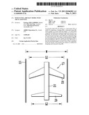
[0021] FIG. 1 shows a schematic plan view of a full scaled aircraft model.
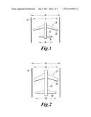
[0022] FIG. 2 shows a schematic plan view of an aircraft model according to the present invention.
[0023] FIG. 3 shows a schematic view of the downwash produced by the aircraft wing.
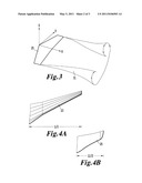
[0024] FIG. 4A shows a schematic plan view of a full scaled wing and FIG. 4b shows a schematic plan view of a truncated wing according to the present invention.
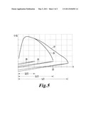
[0025] FIG. 5 show the lift profiles of a full scaled wing and a truncated wing.
DETAILED DESCRIPTION OF THE INVENTION
[0026] Nowadays the design of aircrafts is done using Computational Fluid Dynamics (CFD) and Wind Tunnel Testing (WTT).
[0027] Wind tunnels are installations in which the aerodynamic behaviour of a scaled model of a proposed aircraft can be analysed. They are structures in which wind is produced, usually by a large fan, where the flow passes through one scaled model which is connected to instruments that measure and record the airflow around it and the aerodynamic forces that act upon it. The information obtained in wind tunnels is used for characterising the behaviour of the aircraft model under different flow conditions and therefore allows improving its design.
[0028] The aircraft model is placed in the wind tunnel with a suitable instrumentation to provide the required data. To obtain meaningful data, the flow parameters of Mach number and Reynolds number in the wind tunnel shall match the real aircraft flight conditions.
[0029] The Reynolds number expresses the ratio of inertial (resistant to change or motion) forces to viscous (heavy and gluey) forces. From a detailed analysis of the momentum conservation equation, the inertial forces are characterized by the product of the density r times the velocity V times the gradient of the velocity dV/dx. The viscous forces are characterized by the viscosity coefficient mu times the second gradient of the velocity d 2V/dx 2. The Reynolds number Re then becomes:
Re=(r*V*dV/dx)/(mu*d 2V/dx 2)
Re=(r*V*L)/mu
[0030] where L is some characteristic length of the problem. If the Reynolds number in the wind tunnel and in the field are close, then we properly model the effects of the viscous forces relative to the inertial forces. In the wind tunnels the size of the test section and the power of the fan limit the size of the model and the maximum speed of the flow, limiting the maximum Reynolds in this way.
[0031] Another relevant parameter is the Mach number M, the ratio of the velocity of the object to the speed of sound a.
M=V/a
[0032] The Mach number appears as a scaling parameter in many of the equations for compressible flows, shock waves, and expansions. In wind tunnel testing, the experiment Mach number shall match the real flight conditions Mach number.
[0033] From those theoretical considerations it is clear that for improving the results of the wind tunnel data, the models should be manufactured as large as possible. If the main subject of the wind tunnel testing is a flow investigation around tails and rear fuselage taking into account the influence of the wing, the length of the wing limits the possibilities of expanding its size within the existing wind tunnel test section. If the wind tunnel model rear aircraft scale is chosen in order to maximise the Reynolds number, the corresponding wing length would not fit inside current wind tunnels test section.
[0034] The basic idea of this invention for increasing the size of the aircraft model components placed in the rear part of the aircraft for improving the results of the wind tunnel data using current facilities is truncating the wing since the subject of these kind of tests are the tails and the other components in the rear aircraft, not the wing. The geometry of the reference full span wing is studied and used to build the corresponding truncated wing.
[0035] The new truncated wing is designed in such a way that the downwash in the rear end of the wind tunnel model is the same (very similar) than the downwash generated by the real wing, so that the tails and rear fuselage "do not see" that a new and shortened wing is installed in the model.
[0036] The main difference between the prior art and this invention is illustrated in FIGS. 1 and 2. The maximum size of a prior art full scaled aircraft model 15 whose configuration includes a fuselage 21, a wing 23 and an horizontal tail plane 29 in the rear part of the aircraft is determined by the wind tunnel 11 width W. The rear end of the aircraft model 17 according to this invention has a bigger size compatible with wind tunnel 11 dimensions because its wing 25 is not a full span wing but a truncated wing so that the downwash generated by the wing at the rear end location is the same than the downwash that would be produced by full span wing 23 at the rear end location. In FIG. 3 the downwash produced by wing 25 is illustrated.
[0037] The conditions to be met by said truncated wing 25 having a length L1 in the Y-axis to produce the same downwash than the full span wing 23 having a length L in the Y-axis (using in both cases the same scaling factor for all aircraft model component with the only exception of the wing) are that (see FIGS. 4a, 4b and 5) the shape of the truncated wing 25 has a similar lift span-wise distribution profile 35 to the lift profile 37 of a full length model wing 23 along at least the length L2 of the horizontal tail plane 29.
[0038] An analytical explanation follows.
[0039] Reducing the wing circulation by:
Γ ( y ) b U ∞ = n = 1 ∞ A n sin n θ ##EQU00001## Γ ( y ) = 1 2 U x c ( y ) Cl ( y ) n = 1 ∞ A n sin n θ = 1 2 k ( θ ) Cl α [ α ( θ ) - 1 2 sin θ n = 1 ∞ nA n sin n θ ] A n ##EQU00001.2##
[0040] If the truncated wing has the same An, it has the same lift distribution.
[0041] But, An coefficients for the full wing can be separated into In and an coefficients according to:
A n = I n + α ( π 2 ) a n ##EQU00002##
[0042] where In and an follow the following relations:
n = 1 ∞ I n sin n θ = 1 2 k ( θ ) Cl α [ ( θ ) - 1 2 sin θ n = 1 ∞ nI n sin n θ ] ##EQU00003## n = 1 ∞ a n sin n θ = 1 2 k ( θ ) Cl α [ 1 - 1 2 sin θ n = 1 ∞ na n sin n θ ] ##EQU00003.2##
[0043] As it can be seen, In depends on the dimensionless chord distribution k(θ) and on the twist distribution E(θ) but an depends only on the dimensionless chord distribution k(θ). So, if the chord distribution of the truncated wing is modified to produce the same an, coefficients than the full length wing, we can use this chord distribution in In.
[0044] With the previously obtained wing chord distribution in In, we modify the twist distribution ε(θ) of the truncated wing to have the same In and an coefficients than the full span wing.
[0045] Doing so we have a truncated wing 25 with the same In and an coefficients than the full span wing 23 and therefore the same An coefficients which means the same lift distribution and therefore the same downwash distribution.
[0046] FIG. 5 shows said lift profiles 35, 37 for an embodiment of this invention, as C-CL vs. Y curves, where C-CL stands for Chord in each wing section--Lift in said chord, and Y stands for the lateral distance measured from the aircraft symmetry plane for an angle of attack of 2°. The lower part of FIG. 5 shows schematically the lateral span of the horizontal tail plane 29, the truncated wing 25 and the full scaled wing 23. As it can be easily appreciated the lift profiles 35, 37 of the truncated wing 25 and the wing 23 along the span L2/2 of the horizontal tail plane 29 are almost identical.
[0047] Said embodiment was carried out in a wind tunnel of W=2.78 m. The reference length L/2 of the full scaled wing 23 was 1.38 m and the length L2/2 of the horizontal tail plane 29 was 0.48 m. The length L1/2 of the resulting truncated wing 25 according to the invention was 1 m. Therefore it was achieved a significant size increase of the model rear end part. The span of the aircraft model 17 in the Y-axis shall be lesser than the 75% of the wind tunnel width W so that there is enough distance to the wind tunnel walls to avoid disturbances.
[0048] One of the advantages of this invention is that it achieves an improvement of the quality of the wind tunnel test results without any cost increment because the truncated wing replaces the full span wing. So only one wing would be required to be manufactured for the model, as usual.
[0049] Modifications may be introduced into the preferred embodiment just set forth, which are comprised within the scope defined by the following claims.
Claims:
1. A method for designing a truncated wing (25) with respect to a full
scaled reference wing (23) for an aircraft model (17) whose configuration
also comprises a fuselage (21) and additional components in the rear
aircraft for performing flow investigations around said additional
components in a wind tunnel (11) of width W, characterized by comprising
the following steps: a) obtaining the initial lift distribution In
and the additional lift distribution an in the reference wing (23);
b) defining the length L1 of the truncated wing (25) in the Y-axis; c)
obtaining the truncated wing (25) chord distribution reconstructing the
additional lift distribution an in the reference wing (23) along the
truncated wing (25); d) obtaining the truncated wing (25) twist
distribution reconstructing the initial lift distribution In in the
reference wing (23) along the truncated wing (25); e) keeping the
profiles, the leading edge geometry and the relative thickness
distribution of the reference wing (23) in the truncated wing (25).
2. A method for designing a truncated wing (25) according to claim 1, characterized in that its length L1 is lesser than the 75% of the wind tunnel width W.
3. A method for designing a truncated wing (25) according to claim 1, characterized in that said components in the rear aircraft include an horizontal tail plane (29).
4. An aircraft model (17) for testing in a wind tunnel (11) of width W, whose configuration comprises a fuselage (21), a wing and additional components in the rear aircraft of a maximum length L2 in the Y-axis, characterized in that it is a full scaled model with the exception that it has a truncated wing (25), whose length L1 is lesser than the length L of a full scaled wing (23) but producing the same downwash in said additional components.
5. An aircraft model (17) according to claim 4, characterized in that the full scaled wing (23) and the truncated wing (25) have similar lift profiles (37, 35) along at least the maximum length L2 in the Y-axis of any component in the rear aircraft.
6. An aircraft model (17) according to any of claims 4-5, characterized in that said rear aircraft components include an horizontal tail plane (29).
Description:
FIELD OF THE INVENTION
[0001] The present invention refers to aircraft scaled models used in wind tunnels for analysing its aerodynamic properties and more particularly to aircraft scaled models for analysing the aerodynamic properties of the aircraft tails and rear fuselage.
BACKGROUND OF THE INVENTION
[0002] The performance of aircraft mobile surfaces such as vertical tails, horizontal tail planes, elevators or rudders placed in the rear part of the aircraft is one of the more important issues in global aircraft design. Said surfaces are used as control surfaces, for example a horizontal tail plane is used to control pitch and a rudder is used to control yaw. Therefore its behavior defines aircraft control laws and design constrains.
[0003] When designing the elements composing an aircraft, such as the fuselage, wings, stabilizers, etc. it is necessary to know the aerodynamic properties of such components. In view of the large size of aircrafts, aerodynamic tests are made with scaled models that reproduce the whole or at least a part of the aircraft, the scaled models being subjected to tests in a wind tunnel.
[0004] Those tests are particularly important for the rear part of the aircraft because it is difficult to obtain comprehensive analytical models of its aerodynamic behaviour since the rear part of the aircraft is affected by other parts of an aircraft and particularly by the aircraft wing. For example they can suffer a loss of upstream dynamic pressure due to effects caused by the wing which is difficult to take into account using classical analytical schemes.
[0005] Even though the results currently obtained in wind tunnel tests allow a good understanding of the aerodynamical behaviour of tails and other components of the rear part of the aircraft, they are usually produced at a Reynolds number very much lower than the real aircraft flight Reynolds number and therefore the scaling of the results is sometimes difficult.
[0006] The present invention is intended to improve this drawback.
SUMMARY OF THE INVENTION
[0007] It is an object of the present invention to provide a wing design methodology that, starting from one available reference wing in an aircraft model develops a different twisted and truncated wing with smaller span, that allows to increase the maximum scale of the aircraft model producing a higher Reynolds number during wind tunnel tests as, in this way, the size of the aircraft model wing will not be the part which limits the scale of the model.
[0008] It is another object of the present invention to provide an aircraft model for wind tunnel testing that allows improving the results obtained in flow investigations around tails and rear fuselage.
[0009] It is another object of the present invention to provide an aircraft model for wind tunnel testing that allows optimizing the costs of flow investigations around tails and rear fuselage.
[0010] It is another object of the present invention to provide an aircraft model having a truncated wing that allows reproducing in the aircraft model rear part the flow conditions produced by the reference wing.
[0011] It is another object of the present invention to provide an aircraft model which allows to test the rear part of the aircraft at the maximum Reynolds number allowed, limited only by the size of the aircraft tails and rear parts.
[0012] In one aspect these and other objects are met by providing a method for designing a truncated wing with respect to a full scaled reference wing in an aircraft model whose configuration also comprises a fuselage and additional components in the rear aircraft for performing flow investigations around said additional components in a wind tunnel of width W, comprising the following steps: [0013] Obtaining the initial lift distribution In and the additional lift distribution an in the reference wing. [0014] Defining the length L1 of the truncated wing in the Y-axis. [0015] Obtaining the truncated wing chord distribution reconstructing the additional lift distribution an in the reference wing along the truncated wing. [0016] Obtaining the truncated wing twist distribution reconstructing the initial lift distribution In in the reference wing along the truncated wing. [0017] Keeping the profiles, the leading edge geometry and the relative thickness distribution of the reference wing in the truncated wing.
[0018] In another aspect the above-mentioned objects are met by providing an aircraft model whose configuration comprises a fuselage, the wing and additional components in the rear aircraft, which is a model built with the maximum scale allowed by the wind tunnel test section dimensions with the exception that it has a truncated wing having a length L1 lesser than the length L of a full scaled wing but producing the same downwash in the rear aircraft.
[0019] In a preferred embodiment, said truncated wing geometry produces a similar lift distribution than the one produced by the full span model wing along at least the maximum length L2 in the Y-axis of any component in the rear aircraft. Hereby, it is achieved an aircraft model as large as possible in the rear aircraft for improving the results of wind tunnel data.
[0020] Other characteristics and advantages of the present invention will be clear from the following detailed description of embodiments illustrative of its object in relation to the attached figures.
DESCRIPTION OF THE DRAWINGS
[0021] FIG. 1 shows a schematic plan view of a full scaled aircraft model.
[0022] FIG. 2 shows a schematic plan view of an aircraft model according to the present invention.
[0023] FIG. 3 shows a schematic view of the downwash produced by the aircraft wing.
[0024] FIG. 4A shows a schematic plan view of a full scaled wing and FIG. 4b shows a schematic plan view of a truncated wing according to the present invention.
[0025] FIG. 5 show the lift profiles of a full scaled wing and a truncated wing.
DETAILED DESCRIPTION OF THE INVENTION
[0026] Nowadays the design of aircrafts is done using Computational Fluid Dynamics (CFD) and Wind Tunnel Testing (WTT).
[0027] Wind tunnels are installations in which the aerodynamic behaviour of a scaled model of a proposed aircraft can be analysed. They are structures in which wind is produced, usually by a large fan, where the flow passes through one scaled model which is connected to instruments that measure and record the airflow around it and the aerodynamic forces that act upon it. The information obtained in wind tunnels is used for characterising the behaviour of the aircraft model under different flow conditions and therefore allows improving its design.
[0028] The aircraft model is placed in the wind tunnel with a suitable instrumentation to provide the required data. To obtain meaningful data, the flow parameters of Mach number and Reynolds number in the wind tunnel shall match the real aircraft flight conditions.
[0029] The Reynolds number expresses the ratio of inertial (resistant to change or motion) forces to viscous (heavy and gluey) forces. From a detailed analysis of the momentum conservation equation, the inertial forces are characterized by the product of the density r times the velocity V times the gradient of the velocity dV/dx. The viscous forces are characterized by the viscosity coefficient mu times the second gradient of the velocity d 2V/dx 2. The Reynolds number Re then becomes:
Re=(r*V*dV/dx)/(mu*d 2V/dx 2)
Re=(r*V*L)/mu
[0030] where L is some characteristic length of the problem. If the Reynolds number in the wind tunnel and in the field are close, then we properly model the effects of the viscous forces relative to the inertial forces. In the wind tunnels the size of the test section and the power of the fan limit the size of the model and the maximum speed of the flow, limiting the maximum Reynolds in this way.
[0031] Another relevant parameter is the Mach number M, the ratio of the velocity of the object to the speed of sound a.
M=V/a
[0032] The Mach number appears as a scaling parameter in many of the equations for compressible flows, shock waves, and expansions. In wind tunnel testing, the experiment Mach number shall match the real flight conditions Mach number.
[0033] From those theoretical considerations it is clear that for improving the results of the wind tunnel data, the models should be manufactured as large as possible. If the main subject of the wind tunnel testing is a flow investigation around tails and rear fuselage taking into account the influence of the wing, the length of the wing limits the possibilities of expanding its size within the existing wind tunnel test section. If the wind tunnel model rear aircraft scale is chosen in order to maximise the Reynolds number, the corresponding wing length would not fit inside current wind tunnels test section.
[0034] The basic idea of this invention for increasing the size of the aircraft model components placed in the rear part of the aircraft for improving the results of the wind tunnel data using current facilities is truncating the wing since the subject of these kind of tests are the tails and the other components in the rear aircraft, not the wing. The geometry of the reference full span wing is studied and used to build the corresponding truncated wing.
[0035] The new truncated wing is designed in such a way that the downwash in the rear end of the wind tunnel model is the same (very similar) than the downwash generated by the real wing, so that the tails and rear fuselage "do not see" that a new and shortened wing is installed in the model.
[0036] The main difference between the prior art and this invention is illustrated in FIGS. 1 and 2. The maximum size of a prior art full scaled aircraft model 15 whose configuration includes a fuselage 21, a wing 23 and an horizontal tail plane 29 in the rear part of the aircraft is determined by the wind tunnel 11 width W. The rear end of the aircraft model 17 according to this invention has a bigger size compatible with wind tunnel 11 dimensions because its wing 25 is not a full span wing but a truncated wing so that the downwash generated by the wing at the rear end location is the same than the downwash that would be produced by full span wing 23 at the rear end location. In FIG. 3 the downwash produced by wing 25 is illustrated.
[0037] The conditions to be met by said truncated wing 25 having a length L1 in the Y-axis to produce the same downwash than the full span wing 23 having a length L in the Y-axis (using in both cases the same scaling factor for all aircraft model component with the only exception of the wing) are that (see FIGS. 4a, 4b and 5) the shape of the truncated wing 25 has a similar lift span-wise distribution profile 35 to the lift profile 37 of a full length model wing 23 along at least the length L2 of the horizontal tail plane 29.
[0038] An analytical explanation follows.
[0039] Reducing the wing circulation by:
Γ ( y ) b U ∞ = n = 1 ∞ A n sin n θ ##EQU00001## Γ ( y ) = 1 2 U x c ( y ) Cl ( y ) n = 1 ∞ A n sin n θ = 1 2 k ( θ ) Cl α [ α ( θ ) - 1 2 sin θ n = 1 ∞ nA n sin n θ ] A n ##EQU00001.2##
[0040] If the truncated wing has the same An, it has the same lift distribution.
[0041] But, An coefficients for the full wing can be separated into In and an coefficients according to:
A n = I n + α ( π 2 ) a n ##EQU00002##
[0042] where In and an follow the following relations:
n = 1 ∞ I n sin n θ = 1 2 k ( θ ) Cl α [ ( θ ) - 1 2 sin θ n = 1 ∞ nI n sin n θ ] ##EQU00003## n = 1 ∞ a n sin n θ = 1 2 k ( θ ) Cl α [ 1 - 1 2 sin θ n = 1 ∞ na n sin n θ ] ##EQU00003.2##
[0043] As it can be seen, In depends on the dimensionless chord distribution k(θ) and on the twist distribution E(θ) but an depends only on the dimensionless chord distribution k(θ). So, if the chord distribution of the truncated wing is modified to produce the same an, coefficients than the full length wing, we can use this chord distribution in In.
[0044] With the previously obtained wing chord distribution in In, we modify the twist distribution ε(θ) of the truncated wing to have the same In and an coefficients than the full span wing.
[0045] Doing so we have a truncated wing 25 with the same In and an coefficients than the full span wing 23 and therefore the same An coefficients which means the same lift distribution and therefore the same downwash distribution.
[0046] FIG. 5 shows said lift profiles 35, 37 for an embodiment of this invention, as C-CL vs. Y curves, where C-CL stands for Chord in each wing section--Lift in said chord, and Y stands for the lateral distance measured from the aircraft symmetry plane for an angle of attack of 2°. The lower part of FIG. 5 shows schematically the lateral span of the horizontal tail plane 29, the truncated wing 25 and the full scaled wing 23. As it can be easily appreciated the lift profiles 35, 37 of the truncated wing 25 and the wing 23 along the span L2/2 of the horizontal tail plane 29 are almost identical.
[0047] Said embodiment was carried out in a wind tunnel of W=2.78 m. The reference length L/2 of the full scaled wing 23 was 1.38 m and the length L2/2 of the horizontal tail plane 29 was 0.48 m. The length L1/2 of the resulting truncated wing 25 according to the invention was 1 m. Therefore it was achieved a significant size increase of the model rear end part. The span of the aircraft model 17 in the Y-axis shall be lesser than the 75% of the wind tunnel width W so that there is enough distance to the wind tunnel walls to avoid disturbances.
[0048] One of the advantages of this invention is that it achieves an improvement of the quality of the wind tunnel test results without any cost increment because the truncated wing replaces the full span wing. So only one wing would be required to be manufactured for the model, as usual.
[0049] Modifications may be introduced into the preferred embodiment just set forth, which are comprised within the scope defined by the following claims.
User Contributions:
Comment about this patent or add new information about this topic:
Images included with this patent application:
 |  |
 |  |
| New patent applications in this class: | |
| Date | Title |
|---|---|
| 2022-05-05 | Wire harness designing method and design support device |
| 2022-05-05 | Smart infrastructure |
| 2022-05-05 | Systems and methods for point cloud site commissioning |
| 2022-05-05 | Building management system with configuration by building model augmentation |
| 2022-05-05 | Cell shrink wrap |
| New patent applications from these inventors: | |
| Date | Title |
|---|---|
| 2009-11-05 | Minimum aerodynamic interference support for models in a cryogenic wind tunnel |
| Top Inventors for class "Data processing: structural design, modeling, simulation, and emulation" | |
| Rank | Inventor's name |
|---|---|
| 1 | Dorin Comaniciu |
| 2 | Charles A. Taylor |
| 3 | Bogdan Georgescu |
| 4 | Jiun-Der Yu |
| 5 | Rune Fisker |