Patent application title: PROTECTIVE CAP FOR COATED HEAT SINK AND HEAT SINK MODULE HAVING THE SAME
Inventors:
Jian Liu (Shenzhen City, CN)
Jing Zhang (Shenzhen City, CN)
Assignees:
FU ZHUN PRECISION INDUSTRY (SHEN ZHEN) CO., LTD.
FOXCONN TECHNOLOGY CO., LTD.
IPC8 Class: AF28F1900FI
USPC Class:
1651341
Class name: Heat exchange with protector or protective agent
Publication date: 2011-05-05
Patent application number: 20110100613
odule includes a heat sink, a thermal interface
material and a protective cap. The heat sink includes a base and a heat
conducting block integrally projecting from a bottom surface of the base.
The thermal interface material is disposed on a bottom surface of the
heat conducting block. The protective cap is removably attached to the
heat conducting block to cover the thermal interface material therein.
The protective cap includes a cover and a stepped flange extending
outwardly from a periphery edge of the cover.Claims:
1. A heat sink module comprising: a heat sink comprising a base and a
heat conducting block projecting from a bottom surface of the base; a
thermal interface material disposed on a bottom surface of the heat
conducting block; and a protective cap removably attached to the heat
conducting block to cover the thermal interface material therein, wherein
the protective cap comprises a cover and a stepped flange extending
outwardly from a peripheral edge of the cover.
2. The heat sink module of claim 1, wherein the protective cap is a single, monolithic body made of plastic.
3. The heat sink module of claim 1, wherein the cover comprises a bottom wall and a polygon-shaped side wall extending from a circumference of the bottom wall, and the bottom wall and the side wall commonly define a hollow, polyhedral protrusion with a corresponding cavity therein to protectively cover the thermal interface material.
4. The heat sink module of claim 3, wherein the flange extends from a top of the side wall and comprises a first section and a second section, the side wall comprises a first portion between the first section of the flange and the bottom wall, and a second portion between the second section of the flange and the bottom wall, and a height of the first portion is larger than that of the second portion.
5. The heat sink module of claim 4, wherein the first section of the flange contacts the bottom surface of the base, and the second section of the flange is spaced from the bottom surface of the base a predetermined distance.
6. The heat sink module of claim 5, wherein the height of the first portion of the side wall of the cover is larger than that of the heat conducting block.
7. The heat sink module of claim 1, wherein the thermal interface material is one of thermal grease and phase change material.
8. The heat sink module of claim 1, wherein the heat sink further comprises a fin assembly integrally projecting from a top surface of the base.
9. A protective cap comprising: a cover comprising a bottom wall and a polygon-shaped side wall extending from a circumference of the bottom wall; and a peripheral, stepped flange extending outwardly from a top of the side wall, the flange comprising a first section and a second section; wherein the side wall of the cover comprises a first portion between the first section of the flange and the bottom wall, and a second portion between the second section of the flange and the bottom wall, and a height of the first portion is larger than that of the second portion.
10. The protective cap of claim 9, wherein the protective cap is plastic and has an integral configuration.
11. The protective cap of claim 9, wherein the bottom wall and the side wall commonly define a hollow, polyhedral protrusion with a corresponding cavity therein.
12. The protective cap of claim 9, wherein the flange comprises a connection section obliquely connected between the first section and the second section.
13. A heat sink module comprising: a heat sink comprising a base and a heat conducting block integrally projecting from a bottom surface of the base; a thermal interface material disposed on a bottom surface of the heat conducting block; and a protective cap removably attached to the heat conducting block to enclose the thermal interface material therein; wherein the protective cap comprises a cover and a flange extending outwardly from a top edge of the cover, the cover comprises a bottom wall and a polygon-shaped side wall extending up from a circumference of the bottom wall, the flange comprises a first section and a second section, and a distance between any point of the first section of the flange and the bottom wall is larger than that between any point of the second section of the flange and the bottom wall.
14. The heat sink module of claim 13, wherein the protective cap is plastic and has an integral configuration.
15. The heat sink module of claim 13, wherein the bottom wall and the side wall cooperatively define a hollow, polyhedral protrusion with a corresponding cavity therein to protectively cover the thermal interface material.
16. The heat sink module of claim 13, wherein the side wall comprises a first portion between the first section of the flange and the bottom wall, and a second portion between the second section of the flange and the bottom wall, a height of the first portion of the flange is larger than that of the second portion of the flange.
17. The heat sink module of claim 16, wherein the first section of the flange contacts the bottom surface of the base, and the second section of the flange spaces the bottom surface of the base for a predetermined distance.
18. The heat sink module of claim 17, wherein the height of the first portion of the side wall of the cover is larger than that of the heat conducting block.
19. The heat sink module of claim 13, wherein the thermal interface material is one of thermal grease or phase change material.
20. The heat sink module of claim 13, wherein a fin assembly integrally projecting from the base away from a top surface of the base.Description:
BACKGROUND
[0001] 1. Technical Field
[0002] The disclosure relates to a protective cap for enclosing a coating such as thermal grease applied on a heat sink, and to a heat sink module including the heat sink and the protective cap.
[0003] 2. Description of Related Art
[0004] Heat sinks made by aluminum extrusion or with folded fins are popularly used to dissipate heat generated by electronic devices, for example, CPUs (central processing units). A conventional heat sink includes a base and a number of fins protruding from a top surface of the base. A bottom surface of the base is configured to thermally contact a CPU. A thermal grease is applied to the bottom surface of the base to help rapidly transfer the heat generated by the CPU to the heat sink. The heat generated by the CPU causes the thermal grease to become viscous thereby filling air gaps between the base of the heat sink and the CPU. The thermal grease is applied to the base of the heat sink in advance, prior to assembly of the heat sink with the CPU. However, the thermal grease is not always solid at certain ambient temperatures, and may contaminate surrounding articles. In addition, in a variety of ambient environments, the thermal grease may be contaminated by dust or foreign particles before the heat sink is assembled to the CPU.
[0005] The above-described considerations also similarly apply with regard to other types of thermal interface materials such as phase change material.
[0006] What is needed, therefore, is a means for controlling thermal interface material applied on a heat sink, which means can overcome the above-described shortcomings. A heat sink module including such means is also desired.
BRIEF DESCRIPTION OF THE DRAWINGS
[0007] Many aspects of the present protective cap and heat sink module can be better understood with reference to the following drawings. The components in the drawings are not necessarily drawn to scale, the emphasis instead being placed upon clearly illustrating the principles of the present protective cap and heat sink module. Moreover, in the drawings, like reference numerals designate corresponding parts throughout the several views.
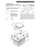
[0008] FIG. 1 is an isometric, exploded view of a heat sink module including a heat sink and a protective cap in accordance with an exemplary embodiment of the disclosure, showing the heat sink module inverted.
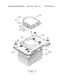
[0009] FIG. 2 is similar to FIG. 1, but shows the protective cap in the process of being assembled to the heat sink.
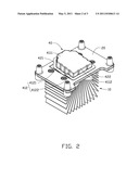
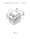
[0010] FIG. 3 is an assembled view of FIG. 1.
DETAILED DESCRIPTION
[0011] Referring to FIG. 1, an exemplary heat sink module includes a heat sink 10, a mounting plate 20, a thermal interface material 30 and a protective cap 40.
[0012] The heat sink 10 includes a base 110, a heat conducting block 120 integrally projecting from a bottom surface of the base 110, and a fin assembly 130 integrally projecting from a top surface of the base 110. The mounting plate 20 is configured to secure the heat sink 10 to other structures such as a printed circuit board (not shown) of a CPU module (not shown). The mounting plate 20 is disposed on the bottom surface of the base 110, and defines an opening. The heat conducting block 120 extends through the opening. The mounting plate 20 is secured to the heat sink 10 by a number of screws 50.
[0013] The heat conducting block 120 includes a bottom surface 121 thermally contacting a CPU of the CPU module, and a number of side surfaces 122 perpendicularly connecting a circumference of the bottom surface 121. The thermal interface material 30 can be thermal grease or phase change material. In the present embodiment, the thermal interface material 30 is thermal grease. The thermal interface material 30 is uniformly spread on a central portion of the bottom surface 121 of the heat conducting block 120 by a printing process, for example, a screen printing process.
[0014] The protective cap 40 is removably attached to the heat conducting block 120 to cover the thermal interface material 30 therein. Therefore during transportation or handling of the heat sink 10, the thermal interface material 30 is apt to not contaminate surrounding articles and not be contaminated by dust or foreign particles. The protective cap 40 is made by pressing a plastic sheet to have a predetermined configuration. Thus the protective cap 40 is a single, monolithic body of the same material. The protective cap 40 has a cover 41, and a peripheral, stepped flange 42 extending outwardly from a peripheral edge of the cover 41. The cover 41 includes a bottom wall 411, and a polygon-shaped side wall 412 perpendicularly extending from a circumference of the bottom wall 411. The bottom wall 411 and the side wall 412 commonly define a hollow, polyhedral protrusion with a corresponding cavity therein to protectively cover the thermal interface material 30. The bottom wall 411 has a first side 4111 (i.e., a front side) and an opposite second side 4112 (i.e., a rear side). The flange 42 includes a first section 421, a second section 422, and a pair of connection sections 423 connected between the first and second sections 421, 422. The side wall 412 includes a first portion 4121 and a second portion 4122. The first portion 4121 is connected between the first side 4111 of the bottom wall 411 and the first section 421 of the flange 42. The second portion 4122 is connected between the second side 4112 of the bottom wall 411 and the second section 422 of the flange 42.
[0015] The first section 421 of the flange 42 extends horizontally and outwardly from a top edge of the first portion 4121 of the side wall 412. The second section 422 of the flange 42 extends horizontally and outwardly from a top edge of the second portion 4122 of the side wall 412. A distance between the first section 421 and the bottom wall 411 is larger than a distance between the second section 422 and the bottom wall 411. That is, a height of the first portion 4121 is larger than that of the second portion 4122. Thus the connection sections 423 are obliquely connected between the first and second sections 421, 422. The first section 421, the second section 422 and the connection sections 423 cooperatively form the stepped flange 42.
[0016] The shape and size of the side wall 412 of the cover 41 of the protective cap 40 are similar to the shape and size of the combination of the side surfaces 122 of the heat conducting block 120. Thus the flange 42 can fitly clip the side surfaces 122 of the heat conducting block 120, thereby attaching the protective cap 40 on the heat conducting block 120. A minimum distance between the bottom wall 411 of the cover 41 and the bottom surface of the base 110 is larger than a height (thickness) of the heat conducting block 120. Thus when the protective cap 40 is attached on the heat conducting block 120, the bottom wall 411 of the cover 41 cannot contact the thermal interface material 30 disposed on the bottom surface 121 of the heat conducting block 120.
[0017] In the present embodiment, the minimum distance between the bottom wall 411 of the cover 41 and the bottom surface of the base 110, i.e., a minimum height of the first portion 4121 of the side wall 412, is larger than the height of the heat conducting block 120. In addition, the height of the first portion 4121 of the side wall 412 is larger than that of the second portion 4122 of the side wall 412. Therefore when the protective cap 40 is attached on the heat conducting block 120, the first section 421 of the flange 42 contacts the bottom surface of the base 110 of the heat sink 10, and the second section 422 of the flange 42 and the bottom surface of the base 110 of the heat sink 10 are spaced apart from each other a predetermined distance. Due to the relationship between the second section 422 of the flange 42 and the bottom surface of the base 110, the second section 422 of the flange 42 functions as an operation part of the protective cap 40, by which the protective cap 40 can be easily attached to or removed from the heat conducting block 120.
[0018] Referring to FIG. 2, to assemble the protective cap 40 to the heat conducting block 120, the second section 422 of the flange 42 is pressed on a surface of the mounting plate 20. Due to a difference in height between the first section 421 of the flange 42 and the second section 422 of the flange 42, the protective cap 40 is initially oblique to the mounting plate 20. Then the front side of the cover 41 of the protective cap 40 is deformably pulled away from the second section 422 of the flange 42 and then pulled down (as viewed in FIG. 2), to enable the protective cap 40 to cover the heat conducting block 120. The front side of the cover 41 is released, thereby also releasing the second section 422 of the flange 42, and the first and second sections 421, 422 of the flange 42 surround and clip the side surfaces 122 of the heat conducting block 120. As shown in FIG. 3, after the protective cap 40 is assembled to the heat sink 10, the first section 421 of the flange 42 contacts the bottom surface of the base 110, and the second section 422 of the flange 42 is spaced apart from the bottom surface of the base 110.
[0019] Unlike with a conventional heat sink module, the thermal interface material 30 disposed on the heat sink 10 can be covered by the protective cap 40. Thus, the thermal interface material 30 is apt to not contaminate surrounding articles and not be contaminated by dust or foreign particles before the heat sink 10 is assembled to other structures. In addition, due to the protective cap 40 having the stepped flange 42, the protective cap 40 can be easily assembled to or dissembled from the heat sink 10.
[0020] It is to be understood, however, that even though numerous characteristics and advantages of the present embodiments have been set forth in the foregoing description, together with details of the configurations and functions of the embodiments, the disclosure is illustrative only, and changes may be made in detail, especially in matters of shape, size, and arrangement of parts within the principles of the embodiments to the full extent indicated by the broad general meaning of the terms in which the appended claims are expressed.
Claims:
1. A heat sink module comprising: a heat sink comprising a base and a
heat conducting block projecting from a bottom surface of the base; a
thermal interface material disposed on a bottom surface of the heat
conducting block; and a protective cap removably attached to the heat
conducting block to cover the thermal interface material therein, wherein
the protective cap comprises a cover and a stepped flange extending
outwardly from a peripheral edge of the cover.
2. The heat sink module of claim 1, wherein the protective cap is a single, monolithic body made of plastic.
3. The heat sink module of claim 1, wherein the cover comprises a bottom wall and a polygon-shaped side wall extending from a circumference of the bottom wall, and the bottom wall and the side wall commonly define a hollow, polyhedral protrusion with a corresponding cavity therein to protectively cover the thermal interface material.
4. The heat sink module of claim 3, wherein the flange extends from a top of the side wall and comprises a first section and a second section, the side wall comprises a first portion between the first section of the flange and the bottom wall, and a second portion between the second section of the flange and the bottom wall, and a height of the first portion is larger than that of the second portion.
5. The heat sink module of claim 4, wherein the first section of the flange contacts the bottom surface of the base, and the second section of the flange is spaced from the bottom surface of the base a predetermined distance.
6. The heat sink module of claim 5, wherein the height of the first portion of the side wall of the cover is larger than that of the heat conducting block.
7. The heat sink module of claim 1, wherein the thermal interface material is one of thermal grease and phase change material.
8. The heat sink module of claim 1, wherein the heat sink further comprises a fin assembly integrally projecting from a top surface of the base.
9. A protective cap comprising: a cover comprising a bottom wall and a polygon-shaped side wall extending from a circumference of the bottom wall; and a peripheral, stepped flange extending outwardly from a top of the side wall, the flange comprising a first section and a second section; wherein the side wall of the cover comprises a first portion between the first section of the flange and the bottom wall, and a second portion between the second section of the flange and the bottom wall, and a height of the first portion is larger than that of the second portion.
10. The protective cap of claim 9, wherein the protective cap is plastic and has an integral configuration.
11. The protective cap of claim 9, wherein the bottom wall and the side wall commonly define a hollow, polyhedral protrusion with a corresponding cavity therein.
12. The protective cap of claim 9, wherein the flange comprises a connection section obliquely connected between the first section and the second section.
13. A heat sink module comprising: a heat sink comprising a base and a heat conducting block integrally projecting from a bottom surface of the base; a thermal interface material disposed on a bottom surface of the heat conducting block; and a protective cap removably attached to the heat conducting block to enclose the thermal interface material therein; wherein the protective cap comprises a cover and a flange extending outwardly from a top edge of the cover, the cover comprises a bottom wall and a polygon-shaped side wall extending up from a circumference of the bottom wall, the flange comprises a first section and a second section, and a distance between any point of the first section of the flange and the bottom wall is larger than that between any point of the second section of the flange and the bottom wall.
14. The heat sink module of claim 13, wherein the protective cap is plastic and has an integral configuration.
15. The heat sink module of claim 13, wherein the bottom wall and the side wall cooperatively define a hollow, polyhedral protrusion with a corresponding cavity therein to protectively cover the thermal interface material.
16. The heat sink module of claim 13, wherein the side wall comprises a first portion between the first section of the flange and the bottom wall, and a second portion between the second section of the flange and the bottom wall, a height of the first portion of the flange is larger than that of the second portion of the flange.
17. The heat sink module of claim 16, wherein the first section of the flange contacts the bottom surface of the base, and the second section of the flange spaces the bottom surface of the base for a predetermined distance.
18. The heat sink module of claim 17, wherein the height of the first portion of the side wall of the cover is larger than that of the heat conducting block.
19. The heat sink module of claim 13, wherein the thermal interface material is one of thermal grease or phase change material.
20. The heat sink module of claim 13, wherein a fin assembly integrally projecting from the base away from a top surface of the base.
Description:
BACKGROUND
[0001] 1. Technical Field
[0002] The disclosure relates to a protective cap for enclosing a coating such as thermal grease applied on a heat sink, and to a heat sink module including the heat sink and the protective cap.
[0003] 2. Description of Related Art
[0004] Heat sinks made by aluminum extrusion or with folded fins are popularly used to dissipate heat generated by electronic devices, for example, CPUs (central processing units). A conventional heat sink includes a base and a number of fins protruding from a top surface of the base. A bottom surface of the base is configured to thermally contact a CPU. A thermal grease is applied to the bottom surface of the base to help rapidly transfer the heat generated by the CPU to the heat sink. The heat generated by the CPU causes the thermal grease to become viscous thereby filling air gaps between the base of the heat sink and the CPU. The thermal grease is applied to the base of the heat sink in advance, prior to assembly of the heat sink with the CPU. However, the thermal grease is not always solid at certain ambient temperatures, and may contaminate surrounding articles. In addition, in a variety of ambient environments, the thermal grease may be contaminated by dust or foreign particles before the heat sink is assembled to the CPU.
[0005] The above-described considerations also similarly apply with regard to other types of thermal interface materials such as phase change material.
[0006] What is needed, therefore, is a means for controlling thermal interface material applied on a heat sink, which means can overcome the above-described shortcomings. A heat sink module including such means is also desired.
BRIEF DESCRIPTION OF THE DRAWINGS
[0007] Many aspects of the present protective cap and heat sink module can be better understood with reference to the following drawings. The components in the drawings are not necessarily drawn to scale, the emphasis instead being placed upon clearly illustrating the principles of the present protective cap and heat sink module. Moreover, in the drawings, like reference numerals designate corresponding parts throughout the several views.
[0008] FIG. 1 is an isometric, exploded view of a heat sink module including a heat sink and a protective cap in accordance with an exemplary embodiment of the disclosure, showing the heat sink module inverted.
[0009] FIG. 2 is similar to FIG. 1, but shows the protective cap in the process of being assembled to the heat sink.
[0010] FIG. 3 is an assembled view of FIG. 1.
DETAILED DESCRIPTION
[0011] Referring to FIG. 1, an exemplary heat sink module includes a heat sink 10, a mounting plate 20, a thermal interface material 30 and a protective cap 40.
[0012] The heat sink 10 includes a base 110, a heat conducting block 120 integrally projecting from a bottom surface of the base 110, and a fin assembly 130 integrally projecting from a top surface of the base 110. The mounting plate 20 is configured to secure the heat sink 10 to other structures such as a printed circuit board (not shown) of a CPU module (not shown). The mounting plate 20 is disposed on the bottom surface of the base 110, and defines an opening. The heat conducting block 120 extends through the opening. The mounting plate 20 is secured to the heat sink 10 by a number of screws 50.
[0013] The heat conducting block 120 includes a bottom surface 121 thermally contacting a CPU of the CPU module, and a number of side surfaces 122 perpendicularly connecting a circumference of the bottom surface 121. The thermal interface material 30 can be thermal grease or phase change material. In the present embodiment, the thermal interface material 30 is thermal grease. The thermal interface material 30 is uniformly spread on a central portion of the bottom surface 121 of the heat conducting block 120 by a printing process, for example, a screen printing process.
[0014] The protective cap 40 is removably attached to the heat conducting block 120 to cover the thermal interface material 30 therein. Therefore during transportation or handling of the heat sink 10, the thermal interface material 30 is apt to not contaminate surrounding articles and not be contaminated by dust or foreign particles. The protective cap 40 is made by pressing a plastic sheet to have a predetermined configuration. Thus the protective cap 40 is a single, monolithic body of the same material. The protective cap 40 has a cover 41, and a peripheral, stepped flange 42 extending outwardly from a peripheral edge of the cover 41. The cover 41 includes a bottom wall 411, and a polygon-shaped side wall 412 perpendicularly extending from a circumference of the bottom wall 411. The bottom wall 411 and the side wall 412 commonly define a hollow, polyhedral protrusion with a corresponding cavity therein to protectively cover the thermal interface material 30. The bottom wall 411 has a first side 4111 (i.e., a front side) and an opposite second side 4112 (i.e., a rear side). The flange 42 includes a first section 421, a second section 422, and a pair of connection sections 423 connected between the first and second sections 421, 422. The side wall 412 includes a first portion 4121 and a second portion 4122. The first portion 4121 is connected between the first side 4111 of the bottom wall 411 and the first section 421 of the flange 42. The second portion 4122 is connected between the second side 4112 of the bottom wall 411 and the second section 422 of the flange 42.
[0015] The first section 421 of the flange 42 extends horizontally and outwardly from a top edge of the first portion 4121 of the side wall 412. The second section 422 of the flange 42 extends horizontally and outwardly from a top edge of the second portion 4122 of the side wall 412. A distance between the first section 421 and the bottom wall 411 is larger than a distance between the second section 422 and the bottom wall 411. That is, a height of the first portion 4121 is larger than that of the second portion 4122. Thus the connection sections 423 are obliquely connected between the first and second sections 421, 422. The first section 421, the second section 422 and the connection sections 423 cooperatively form the stepped flange 42.
[0016] The shape and size of the side wall 412 of the cover 41 of the protective cap 40 are similar to the shape and size of the combination of the side surfaces 122 of the heat conducting block 120. Thus the flange 42 can fitly clip the side surfaces 122 of the heat conducting block 120, thereby attaching the protective cap 40 on the heat conducting block 120. A minimum distance between the bottom wall 411 of the cover 41 and the bottom surface of the base 110 is larger than a height (thickness) of the heat conducting block 120. Thus when the protective cap 40 is attached on the heat conducting block 120, the bottom wall 411 of the cover 41 cannot contact the thermal interface material 30 disposed on the bottom surface 121 of the heat conducting block 120.
[0017] In the present embodiment, the minimum distance between the bottom wall 411 of the cover 41 and the bottom surface of the base 110, i.e., a minimum height of the first portion 4121 of the side wall 412, is larger than the height of the heat conducting block 120. In addition, the height of the first portion 4121 of the side wall 412 is larger than that of the second portion 4122 of the side wall 412. Therefore when the protective cap 40 is attached on the heat conducting block 120, the first section 421 of the flange 42 contacts the bottom surface of the base 110 of the heat sink 10, and the second section 422 of the flange 42 and the bottom surface of the base 110 of the heat sink 10 are spaced apart from each other a predetermined distance. Due to the relationship between the second section 422 of the flange 42 and the bottom surface of the base 110, the second section 422 of the flange 42 functions as an operation part of the protective cap 40, by which the protective cap 40 can be easily attached to or removed from the heat conducting block 120.
[0018] Referring to FIG. 2, to assemble the protective cap 40 to the heat conducting block 120, the second section 422 of the flange 42 is pressed on a surface of the mounting plate 20. Due to a difference in height between the first section 421 of the flange 42 and the second section 422 of the flange 42, the protective cap 40 is initially oblique to the mounting plate 20. Then the front side of the cover 41 of the protective cap 40 is deformably pulled away from the second section 422 of the flange 42 and then pulled down (as viewed in FIG. 2), to enable the protective cap 40 to cover the heat conducting block 120. The front side of the cover 41 is released, thereby also releasing the second section 422 of the flange 42, and the first and second sections 421, 422 of the flange 42 surround and clip the side surfaces 122 of the heat conducting block 120. As shown in FIG. 3, after the protective cap 40 is assembled to the heat sink 10, the first section 421 of the flange 42 contacts the bottom surface of the base 110, and the second section 422 of the flange 42 is spaced apart from the bottom surface of the base 110.
[0019] Unlike with a conventional heat sink module, the thermal interface material 30 disposed on the heat sink 10 can be covered by the protective cap 40. Thus, the thermal interface material 30 is apt to not contaminate surrounding articles and not be contaminated by dust or foreign particles before the heat sink 10 is assembled to other structures. In addition, due to the protective cap 40 having the stepped flange 42, the protective cap 40 can be easily assembled to or dissembled from the heat sink 10.
[0020] It is to be understood, however, that even though numerous characteristics and advantages of the present embodiments have been set forth in the foregoing description, together with details of the configurations and functions of the embodiments, the disclosure is illustrative only, and changes may be made in detail, especially in matters of shape, size, and arrangement of parts within the principles of the embodiments to the full extent indicated by the broad general meaning of the terms in which the appended claims are expressed.
User Contributions:
Comment about this patent or add new information about this topic:
Images included with this patent application:
 |  |
 |  |
| New patent applications in this class: | |
| Date | Title |
|---|---|
| 2019-05-16 | A plate heat exchanger |
| 2016-07-14 | Indirect fired heat exchanger |
| 2016-07-07 | High strength aluminum alloy fin stock for heat exchanger |
| 2016-06-30 | Tube sheet |
| 2016-05-12 | Lifetime diagnosis component for anticorrosive coating, heat exchanger, refrigeration-and-air-conditioning apparatus |
| New patent applications from these inventors: | |
| Date | Title |
|---|---|
| 2014-12-18 | Method and device for displaying microblog dynamics, and computer storage medium |
| 2014-09-04 | Method and device for selecting friends in microblogging |
| 2014-05-01 | Search ranking method and system for community users |
| 2013-12-05 | Method for manufacturing light bar that enhances central point brightness of backlight module |
| 2013-05-02 | Electronic device capable of adjusting orientation of display content in response to rotation of a support |
| Top Inventors for class "Heat exchange" | |
| Rank | Inventor's name |
|---|---|
| 1 | Levi A. Campbell |
| 2 | Chun-Chi Chen |
| 3 | Tai-Her Yang |
| 4 | Robert E. Simons |
| 5 | Richard C. Chu |