Patent application title: ENERGY-SAVING PLAN
Inventors:
Yangde Li (Dongguan, CN)
IPC8 Class: AF28F700FI
USPC Class:
165185
Class name: Heat exchange heat transmitter
Publication date: 2010-11-11
Patent application number: 20100282457
h is characterized in a bottom with a plurality
of lattices, a plurality of radial fins, a plurality of spiral fins, a
plurality of L-shaped protuberances, or a plurality of cylindrical pins
thereby increasing heat absorbing area of said bottom and reducing
reflection of heat energy.Claims:
1. An energy-saving pan having a bottom with a plurality of lattices, a
plurality of radial fins, a plurality of spiral fins, a plurality of
L-shaped protuberances, or a plurality of cylindrical pins thereby
increasing heat absorbing area of said bottom and reducing reflection of
heat energy.Description:
BACKGROUND OF THE INVENTION
[0001]1. Field of the Invention
[0002]This invention is related to an improvement in the structure of a pan, and in particular to one which is energy saving.
[0003]2. Description of the Prior Art
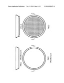
[0004]Recently, all countries in the world advocate the goal of saving energy by increasing the energy efficiency. The commonly used pan (see FIGS. 1 and 2) is very low in heat efficiency, thereby requiring a long time to cook the food thoroughly. The conventional pan has a flat and smooth bottom so that the area of the conventional pan subject to heat is small and most of the heat energy is reflected away by the flat and smooth bottom thus lowering the heat efficiency.
[0005]Therefore, it is an object of the present invention to provide an improved cooking pan which can obviate and mitigate the above-mentioned drawbacks.
SUMMARY OF THE INVENTION
[0006]In order to overcome the drawback of the conventional pan, the present invention utilizes the increase of the heat absorbing area to enhance the heat efficiency of a cooking pan.
[0007]According to the present invention, the energy saving pan has a bottom which is configured to provide lattices, radial fins, spiral fins, L-shaped protuberances or cylindrical pins to increase the heat absorbing area
[0008]As compared with the conventional cooking pan, the present invention has a bottom which is provided with lattices, radial fins, spiral fins, L-shaped protuberances or cylindrical pins thereby providing the bottom with a larger heat absorbing area and reducing the reflection of heat energy from the bottom, and therefore increasing the heat efficiency and saving energy.
[0009]To enable a further understanding of the said objectives and the technological methods of the invention herein, the brief description of the drawings below is followed by the detailed description of the preferred embodiments.
BRIEF DESCRIPTION OF THE DRAWINGS
[0010]FIG. 1 is a bottom view of a conventional cooking pan;
[0011]FIG. 2 is a sectional view taken along line 2-2 of FIG. 1;
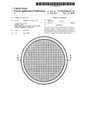
[0012]FIG. 3 is a bottom view of an energy saving pan according to a first preferred embodiment of the present invention;
[0013]FIG. 4 is a sectional view taken along line 4-4 of FIG. 3;
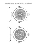
[0014]FIG. 5 is a bottom view of an energy saving pan according to a second preferred embodiment of the present invention;
[0015]FIG. 6 is a sectional view taken along line 6-6 of FIG. 5;
[0016]FIG. 7 is a bottom view of an energy saving pan according to a third preferred embodiment of the present invention;
[0017]FIG. 8 is a sectional view taken along line 8-8 of FIG. 7;
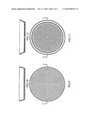
[0018]FIG. 9 is a bottom view of an energy saving pan according to a fourth preferred embodiment of the present invention;
[0019]FIG. 10 is a sectional view taken along line 10-10 of FIG. 9;
[0020]FIG. 11 is a bottom view of an energy saving pan according to a fifth preferred embodiment of the present invention; and
[0021]FIG. 12 is a sectional view taken along line 12-12 of FIG. 11.
DETAILED DESCRIPTION OF THE PREFERRED EMBODIMENTS
[0022]FIGS. 3 and 4 illustrate the energy saving pan according to a first preferred embodiment of the present invention. As shown, the bottom of the energy pan is formed with a plurality of lattices thereby increasing the heat absorbing area and reducing the reflection of heat energy.
[0023]FIGS. 5 and 6 illustrate the energy saving pan according to a second preferred embodiment of the present invention. As shown, the bottom of the energy pan is formed with a plurality of radial fins thereby increasing the heat absorbing area and reducing the reflection of heat energy.
[0024]FIGS. 7 and 8 illustrate the energy saving pan according to a third preferred embodiment of the present invention. As shown, the bottom of the energy pan is formed with a plurality of spiral fins thereby increasing the heat absorbing area and reducing the reflection of heat energy.
[0025]FIGS. 9 and 10 illustrate the energy saving pan according to a fourth preferred embodiment of the present invention. As shown, the bottom of the energy pan is formed with a plurality of L-shaped protuberances thereby increasing the heat absorbing area and reducing the reflection of heat energy.
[0026]FIGS. 11 and 12 illustrate the energy saving pan according to a fifth preferred embodiment of the present invention. As shown, the bottom of the energy pan is formed with a plurality of cylindrical pins thereby increasing the heat absorbing area and reducing the reflection of heat energy.
[0027]The experimental data of the energy saving pans with different bottom structures are listed in the following table:
TABLE-US-00001 Energy saving experiments at room temperature 20° C. Ratio of Surface area of the Increasing Increasing Increasing The time reduced for energy-saving water water water increasing water pan to the Average temperature temperature temperature temperature as Weight conventional Thickness to 50° C. to 80° C. to 100° C. compared to the NO. (g) pan (um) time time time conventional pan 1 Conventional 384 23.8 1'42'' 4'01'' 7'49'' pan 2 530 1.82 17.2 1'44'' 3'45'' 6'16'' 24.70% 3 560 1.46 21 1'45'' 3'45'' 6'14'' 25.40% 4 604 1.85 26.8 1'32'' 3'47'' 6'07'' 27.20% 5 470 1.34 21.4 1'13'' 3'36'' 6'07'' 27.70% 6 515 1.69 22 1'32'' 3'42'' 6'06'' 28.10%
Claims:
1. An energy-saving pan having a bottom with a plurality of lattices, a
plurality of radial fins, a plurality of spiral fins, a plurality of
L-shaped protuberances, or a plurality of cylindrical pins thereby
increasing heat absorbing area of said bottom and reducing reflection of
heat energy.Description:
BACKGROUND OF THE INVENTION
[0001]1. Field of the Invention
[0002]This invention is related to an improvement in the structure of a pan, and in particular to one which is energy saving.
[0003]2. Description of the Prior Art
[0004]Recently, all countries in the world advocate the goal of saving energy by increasing the energy efficiency. The commonly used pan (see FIGS. 1 and 2) is very low in heat efficiency, thereby requiring a long time to cook the food thoroughly. The conventional pan has a flat and smooth bottom so that the area of the conventional pan subject to heat is small and most of the heat energy is reflected away by the flat and smooth bottom thus lowering the heat efficiency.
[0005]Therefore, it is an object of the present invention to provide an improved cooking pan which can obviate and mitigate the above-mentioned drawbacks.
SUMMARY OF THE INVENTION
[0006]In order to overcome the drawback of the conventional pan, the present invention utilizes the increase of the heat absorbing area to enhance the heat efficiency of a cooking pan.
[0007]According to the present invention, the energy saving pan has a bottom which is configured to provide lattices, radial fins, spiral fins, L-shaped protuberances or cylindrical pins to increase the heat absorbing area
[0008]As compared with the conventional cooking pan, the present invention has a bottom which is provided with lattices, radial fins, spiral fins, L-shaped protuberances or cylindrical pins thereby providing the bottom with a larger heat absorbing area and reducing the reflection of heat energy from the bottom, and therefore increasing the heat efficiency and saving energy.
[0009]To enable a further understanding of the said objectives and the technological methods of the invention herein, the brief description of the drawings below is followed by the detailed description of the preferred embodiments.
BRIEF DESCRIPTION OF THE DRAWINGS
[0010]FIG. 1 is a bottom view of a conventional cooking pan;
[0011]FIG. 2 is a sectional view taken along line 2-2 of FIG. 1;
[0012]FIG. 3 is a bottom view of an energy saving pan according to a first preferred embodiment of the present invention;
[0013]FIG. 4 is a sectional view taken along line 4-4 of FIG. 3;
[0014]FIG. 5 is a bottom view of an energy saving pan according to a second preferred embodiment of the present invention;
[0015]FIG. 6 is a sectional view taken along line 6-6 of FIG. 5;
[0016]FIG. 7 is a bottom view of an energy saving pan according to a third preferred embodiment of the present invention;
[0017]FIG. 8 is a sectional view taken along line 8-8 of FIG. 7;
[0018]FIG. 9 is a bottom view of an energy saving pan according to a fourth preferred embodiment of the present invention;
[0019]FIG. 10 is a sectional view taken along line 10-10 of FIG. 9;
[0020]FIG. 11 is a bottom view of an energy saving pan according to a fifth preferred embodiment of the present invention; and
[0021]FIG. 12 is a sectional view taken along line 12-12 of FIG. 11.
DETAILED DESCRIPTION OF THE PREFERRED EMBODIMENTS
[0022]FIGS. 3 and 4 illustrate the energy saving pan according to a first preferred embodiment of the present invention. As shown, the bottom of the energy pan is formed with a plurality of lattices thereby increasing the heat absorbing area and reducing the reflection of heat energy.
[0023]FIGS. 5 and 6 illustrate the energy saving pan according to a second preferred embodiment of the present invention. As shown, the bottom of the energy pan is formed with a plurality of radial fins thereby increasing the heat absorbing area and reducing the reflection of heat energy.
[0024]FIGS. 7 and 8 illustrate the energy saving pan according to a third preferred embodiment of the present invention. As shown, the bottom of the energy pan is formed with a plurality of spiral fins thereby increasing the heat absorbing area and reducing the reflection of heat energy.
[0025]FIGS. 9 and 10 illustrate the energy saving pan according to a fourth preferred embodiment of the present invention. As shown, the bottom of the energy pan is formed with a plurality of L-shaped protuberances thereby increasing the heat absorbing area and reducing the reflection of heat energy.
[0026]FIGS. 11 and 12 illustrate the energy saving pan according to a fifth preferred embodiment of the present invention. As shown, the bottom of the energy pan is formed with a plurality of cylindrical pins thereby increasing the heat absorbing area and reducing the reflection of heat energy.
[0027]The experimental data of the energy saving pans with different bottom structures are listed in the following table:
TABLE-US-00001 Energy saving experiments at room temperature 20° C. Ratio of Surface area of the Increasing Increasing Increasing The time reduced for energy-saving water water water increasing water pan to the Average temperature temperature temperature temperature as Weight conventional Thickness to 50° C. to 80° C. to 100° C. compared to the NO. (g) pan (um) time time time conventional pan 1 Conventional 384 23.8 1'42'' 4'01'' 7'49'' pan 2 530 1.82 17.2 1'44'' 3'45'' 6'16'' 24.70% 3 560 1.46 21 1'45'' 3'45'' 6'14'' 25.40% 4 604 1.85 26.8 1'32'' 3'47'' 6'07'' 27.20% 5 470 1.34 21.4 1'13'' 3'36'' 6'07'' 27.70% 6 515 1.69 22 1'32'' 3'42'' 6'06'' 28.10%
User Contributions:
Comment about this patent or add new information about this topic:
Images included with this patent application:
 |  |
 |  |
| Similar patent applications: | |
| Date | Title |
|---|---|
| 2010-04-15 | Vehicle heat exchangers having shielding channels |
| 2010-07-08 | Heat exchanger having a plastic collecting tank |
| 2010-08-19 | Heat exchangers having baffled manifolds |
| 2010-11-04 | Tubular condensers having tubes with external enhancements |
| 2010-11-25 | Energy transducing apparatus and energy transducing equipment |
| New patent applications from these inventors: | |
| Date | Title |
|---|---|
| 2017-09-14 | Method for forming amorphous alloy part |
| 2017-06-15 | Degradable stent |
| 2010-11-11 | Supermarket video surveillance system |
| Top Inventors for class "Heat exchange" | |
| Rank | Inventor's name |
|---|---|
| 1 | Levi A. Campbell |
| 2 | Chun-Chi Chen |
| 3 | Tai-Her Yang |
| 4 | Robert E. Simons |
| 5 | Richard C. Chu |