Patent application title: COMPUTER ENCLOSURE
Inventors:
Zi-Yu Zhan (Shenzhen City, CN)
Zi-Yu Zhan (Shenzhen City, CN)
Assignees:
HONG FU JIN PRECISION INDUSTRY (ShenZhen) CO., LTD.
HON HAI PRECISION INDUSTRY CO., LTD.
IPC8 Class: AG06F120FI
USPC Class:
36167947
Class name: Computer related housing or mounting assemblies with cooling means plural diverse cooling means integrated into one system; e.g., fan with heat pipe or heat sink, etc.
Publication date: 2010-10-14
Patent application number: 20100259887
udes an absorber plate, a thermoelectric
converter, and a refrigerator. The absorber plate is arranged in the
computer enclosure to absorb heat generated in the computer enclosure.
The thermoelectric converter is arranged in the computer enclosure to
receive heat absorbed by the absorber plate, and then convert the
absorbed heat to electrical energy. The refrigerator is arranged in the
computer enclosure to receive the electrical energy generated by the
thermoelectric converter, and then work to generate cold air to
dissipating heat in the computer enclosure.Claims:
1. A computer enclosure, comprising:an absorber plate arranged in the
computer enclosure, operable to absorb heat generated in the computer
enclosure;a thermoelectric converter arranged in the computer enclosure,
operable to receive heat absorbed by the absorber plate and then convert
the absorbed heat to electrical energy; anda cryostat arranged in the
computer enclosure, operable to receive the electrical energy generated
by the thermoelectric converter and then work to generate cold air to
dissipating heat in the computer enclosure.
2. The computer enclosure of claim 1, further comprising a side plate partially enclosing the absorber plate, the thermoelectric converter, and the cryostat, wherein the absorber plate is rectangular and mounted to an inner wall of the side plate.
3. The computer enclosure of claim 2, wherein a plurality of wavy parallel grooves are defined in the absorber plate, opposite to the side plate.
4. The computer enclosure of claim 2, wherein the thermoelectric converter is mounted on the inner wall of the side plate of the computer enclosure, and in contact with the absorber plate.
5. The computer enclosure of claim 2, wherein a plurality of through holes are defined in the side plate of the computer enclosure, to dissipate heat for the computer enclosure.
6. The computer enclosure of claim 1, wherein an air outlet is defined in the cryostat, to output the cold air.
7. The computer enclosure of claim 6, wherein a blower is arranged in the computer enclosure to improve air flow of the cold air.
8. The computer enclosure of claim 7, wherein the blower is arranged adjacent to the cryostat.
9. The computer enclosure of claim 7, wherein the blower receives the electrical energy generated by the thermoelectric converter to work.
10. The computer enclosure of claim 7, further comprising a front plate partially enclosing the absorber plate, the thermoelectric converter, and the cryostat, wherein the cryostat is mounted to an inner wall of the front plate.
11. The computer enclosure of claim 10, wherein the blower is mounted to the inner wall of the front plate.Description:
BACKGROUND
[0001]1. Technical Field
[0002]The present disclosure relates to a computer enclosure.
[0003]2. Description of Related Art
[0004]In electronic devices, and particularly, computers, heat-generating components, such as central processing units (CPUs), usually generate heat during operation. Generally, a heat sink is mounted on a heat-generating component to dissipate the heat. However, very often, a heat sink for such a heat-generating component cannot fully satisfy the need for dissipating heat when the heat-generating component works in a highly loaded process or a high frequency mode.
BRIEF DESCRIPTION OF THE DRAWINGS
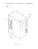
[0005]FIG. 1 is a schematic, isometric view of an exemplary embodiment of a computer enclosure, the computer enclosure including a side plate and a front plate.
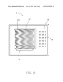
[0006]FIG. 2 is a schematic, isometric view of the side plate of the computer enclosure of FIG. 1, but viewed from another perspective.
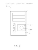
[0007]FIG. 3 is a schematic, isometric view of an exemplary embodiment of the front plate of the computer enclosure of FIG. 1, but viewed from another perspective.
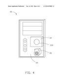
[0008]FIG. 4 is a schematic, isometric view of another exemplary embodiment of the front plate of the computer enclosure of FIG. 1.
DETAILED DESCRIPTION
[0009]Referring to FIG. 1 to FIG. 3, an exemplary embodiment of a computer enclosure 100 includes a side plate 10 and a front plate 20, the side plate 10 defining a plurality of through holes 16 to dissipate heat in the computer enclosure 100.
[0010]An absorber plate 12 is mounted to an inner wall 18 of the side plate 10 of the computer enclosure 100, to absorb heat from some electrical elements (such as a central processing unit, not shown) arranged in the computer enclosure 100. A thermoelectric converter 14 is mounted to the inner wall 18 of the side plate 10 of the computer enclosure 100 in contact with the absorber plate 12, to receive heat energy absorbed by the absorber plate 12, and then convert the heat energy to electrical energy. In one embodiment, the absorber plate 12 is rectangular, and a plurality of wavy parallel grooves 122 defined in the absorber plate 12, to improve heat absorbing efficiency.
[0011]A cryostat 22 is mounted to an inner wall 24 of the front plate 20 of the computer enclosure 100. The cryostat 22 receives the electrical energy generated by the thermoelectric converter 14, and then to work to generate cold air and output the cold air via an air outlet 222 defined in the cryostat 22. The cold air can dissipate heat from the electrical elements in the computer enclosure 1 00.
[0012]Referring to FIG. 4, another exemplary embodiment of the front plate 20 of the computer enclosure 100 is shown. The front plate 20 is similar to the front plate 20 of the above-mentioned embodiment, except that a blower 26 is mounded to the inner wall 24 of the front plate 20, adjacent to the cryostat 22. The blower 26 can receive the electrical energy generated by the thermoelectric converter 14 to improve airflow, namely the cold air generated from the air outlet 222 of the cryostat 22 can effectively flow in the computer enclosure 100 to further improve heat dissipating efficiency.
[0013]It is to be understood, however, that even though numerous characteristics and advantages of the present disclosure have been set forth in the foregoing description, together with details of the structure and function of the disclosure, the disclosure is illustrative only, and changes may be made in details, especially in matters of shape, size, and arrangement of parts within the principles of the disclosure to the full extent indicated by the broad general meaning of the terms in which the appended claims are expressed.
Claims:
1. A computer enclosure, comprising:an absorber plate arranged in the
computer enclosure, operable to absorb heat generated in the computer
enclosure;a thermoelectric converter arranged in the computer enclosure,
operable to receive heat absorbed by the absorber plate and then convert
the absorbed heat to electrical energy; anda cryostat arranged in the
computer enclosure, operable to receive the electrical energy generated
by the thermoelectric converter and then work to generate cold air to
dissipating heat in the computer enclosure.
2. The computer enclosure of claim 1, further comprising a side plate partially enclosing the absorber plate, the thermoelectric converter, and the cryostat, wherein the absorber plate is rectangular and mounted to an inner wall of the side plate.
3. The computer enclosure of claim 2, wherein a plurality of wavy parallel grooves are defined in the absorber plate, opposite to the side plate.
4. The computer enclosure of claim 2, wherein the thermoelectric converter is mounted on the inner wall of the side plate of the computer enclosure, and in contact with the absorber plate.
5. The computer enclosure of claim 2, wherein a plurality of through holes are defined in the side plate of the computer enclosure, to dissipate heat for the computer enclosure.
6. The computer enclosure of claim 1, wherein an air outlet is defined in the cryostat, to output the cold air.
7. The computer enclosure of claim 6, wherein a blower is arranged in the computer enclosure to improve air flow of the cold air.
8. The computer enclosure of claim 7, wherein the blower is arranged adjacent to the cryostat.
9. The computer enclosure of claim 7, wherein the blower receives the electrical energy generated by the thermoelectric converter to work.
10. The computer enclosure of claim 7, further comprising a front plate partially enclosing the absorber plate, the thermoelectric converter, and the cryostat, wherein the cryostat is mounted to an inner wall of the front plate.
11. The computer enclosure of claim 10, wherein the blower is mounted to the inner wall of the front plate.
Description:
BACKGROUND
[0001]1. Technical Field
[0002]The present disclosure relates to a computer enclosure.
[0003]2. Description of Related Art
[0004]In electronic devices, and particularly, computers, heat-generating components, such as central processing units (CPUs), usually generate heat during operation. Generally, a heat sink is mounted on a heat-generating component to dissipate the heat. However, very often, a heat sink for such a heat-generating component cannot fully satisfy the need for dissipating heat when the heat-generating component works in a highly loaded process or a high frequency mode.
BRIEF DESCRIPTION OF THE DRAWINGS
[0005]FIG. 1 is a schematic, isometric view of an exemplary embodiment of a computer enclosure, the computer enclosure including a side plate and a front plate.
[0006]FIG. 2 is a schematic, isometric view of the side plate of the computer enclosure of FIG. 1, but viewed from another perspective.
[0007]FIG. 3 is a schematic, isometric view of an exemplary embodiment of the front plate of the computer enclosure of FIG. 1, but viewed from another perspective.
[0008]FIG. 4 is a schematic, isometric view of another exemplary embodiment of the front plate of the computer enclosure of FIG. 1.
DETAILED DESCRIPTION
[0009]Referring to FIG. 1 to FIG. 3, an exemplary embodiment of a computer enclosure 100 includes a side plate 10 and a front plate 20, the side plate 10 defining a plurality of through holes 16 to dissipate heat in the computer enclosure 100.
[0010]An absorber plate 12 is mounted to an inner wall 18 of the side plate 10 of the computer enclosure 100, to absorb heat from some electrical elements (such as a central processing unit, not shown) arranged in the computer enclosure 100. A thermoelectric converter 14 is mounted to the inner wall 18 of the side plate 10 of the computer enclosure 100 in contact with the absorber plate 12, to receive heat energy absorbed by the absorber plate 12, and then convert the heat energy to electrical energy. In one embodiment, the absorber plate 12 is rectangular, and a plurality of wavy parallel grooves 122 defined in the absorber plate 12, to improve heat absorbing efficiency.
[0011]A cryostat 22 is mounted to an inner wall 24 of the front plate 20 of the computer enclosure 100. The cryostat 22 receives the electrical energy generated by the thermoelectric converter 14, and then to work to generate cold air and output the cold air via an air outlet 222 defined in the cryostat 22. The cold air can dissipate heat from the electrical elements in the computer enclosure 1 00.
[0012]Referring to FIG. 4, another exemplary embodiment of the front plate 20 of the computer enclosure 100 is shown. The front plate 20 is similar to the front plate 20 of the above-mentioned embodiment, except that a blower 26 is mounded to the inner wall 24 of the front plate 20, adjacent to the cryostat 22. The blower 26 can receive the electrical energy generated by the thermoelectric converter 14 to improve airflow, namely the cold air generated from the air outlet 222 of the cryostat 22 can effectively flow in the computer enclosure 100 to further improve heat dissipating efficiency.
[0013]It is to be understood, however, that even though numerous characteristics and advantages of the present disclosure have been set forth in the foregoing description, together with details of the structure and function of the disclosure, the disclosure is illustrative only, and changes may be made in details, especially in matters of shape, size, and arrangement of parts within the principles of the disclosure to the full extent indicated by the broad general meaning of the terms in which the appended claims are expressed.
User Contributions:
Comment about this patent or add new information about this topic:
Images included with this patent application:
 |  |
 |  |
 |
| Similar patent applications: | |
| Date | Title |
|---|---|
| 2011-03-24 | Computer enclosure |
| 2011-06-02 | Computer enclosure |
| 2012-02-02 | Computer enclosure |
| 2012-03-08 | Computer enclosure |
| 2012-03-29 | Computer enclosure |
| New patent applications in this class: | |
| Date | Title |
|---|---|
| 2022-05-05 | Liquid-cooled integrated cabinet |
| 2019-05-16 | Data center system, control method of data center system, and recording medium recording control program of data center system |
| 2019-05-16 | Method for providing cooling to electronic racks using liquid cooling and air cooling |
| 2019-05-16 | Cooling system for a server |
| 2019-05-16 | Data center rack mounted liquid conduction cooling apparatus and method |
| New patent applications from these inventors: | |
| Date | Title |
|---|---|
| 2013-02-21 | Fan speed control device |
| 2012-06-07 | Energy consumption detection system for electronic device |
| 2012-05-24 | Server and method for performing data recovery of the server |
| 2012-04-26 | Data storage device |
| Top Inventors for class "Electricity: electrical systems and devices" | |
| Rank | Inventor's name |
|---|---|
| 1 | Zheng-Heng Sun |
| 2 | Levi A. Campbell |
| 3 | Li-Ping Chen |
| 4 | Robert E. Simons |
| 5 | Richard C. Chu |