Patent application title: SCREW CONNECTION FOR A FIXED CONNECTION OF TWO ASSEMBLIES
Inventors:
Gottfried König (Bad Laasphe, DE)
Gottfried König (Bad Laasphe, DE)
Gottfried König (Bad Laasphe, DE)
Gottfried König (Bad Laasphe, DE)
Uwe Rausch (Tambach-Dietharz, DE)
Assignees:
Ejot GmbH & Co., KG
IPC8 Class: AF16B2500FI
USPC Class:
411418
Class name: Thread or shank structure circumferentially interrupted thread by longitudinal slot
Publication date: 2010-09-30
Patent application number: 20100247268
xed connection of two assemblies which are
mounted to each other in a variable position, using a connecting member
penetrated by a screw. The connecting member is mounted between the
assemblies by means of a self-cutting screw penetrating the connecting
member and one of the assemblies, which screw is grooving its thread into
both parts in such a way that, starting from a stable end position of the
one assembly and the connecting member, the screw is adapted to be
screwed into the connecting member as well as into the one assembly by
means of thread grooves such that, by means of the self-cutting thread of
the screw, the connecting member and the one assembly are held in a fixed
position with respect to each other, and the other assembly is fastened
directly to the connecting member.Claims:
1. Screw connection for a fixed connection of two assemblies which are
mounted to each other in a variable position, using a connecting member
penetrated by a screw, wherein the connecting member is mounted between
the assemblies by means of a self-cutting screw penetrating the
connecting member and one of the assemblies;the screw is grooving its
thread into both parts in such a way that, starting from a stable end
position of the one assembly and the connecting member, the screw is
adapted to be screwed into the connecting member as well as into the one
assembly by means of thread grooves;by means of the self-cutting thread
of the screw, the connecting member and the one assembly are held in a
fixed position with respect to each other; andthe other assembly is
fastened directly to the connecting member.
2. Screw connection according to claim 1, wherein the connecting member and the one assembly are provided with projections each which comprise coaxial bores for taking up of the screw which is adapted to be coaxially screwed into the bores such that the screw screwed into the bores secures the assembly and the connecting member in the position being obtained during screwing-in.
3. Screw connection according to claim 1, wherein the connecting member and the one assembly, respectively, are provided each with several projections provided with a bore.Description:
[0001]The invention relates to a screw connection for a fixed connection
of two assemblies which are mounted in a variable position with respect
to each other, using a connecting member penetrated by a screw.
[0002]Making a fixed connection of two assemblies is frequently encountered, in particular in the area of the production of furniture where furniture parts, in particular those which meat each other at right angels, are to be brought into engagement with each other, wherein a fixed connection is established by means of screws. Therein, the problem is frequently encountered that, because of inaccuracies during production, the respective receiving portions for screws, i.e. a hole for a screw head and a bore for a screw thread, are positioned not coaxially to each other such that is necessary to provide for a possibility for correction. In most cases, this is achieved thereby that a seat serving for receiving a connecting screw, for a cheese head of a screw is embraced with clearance whereby a corresponding possibility for correction is given for a connecting member connecting two furniture parts (here DE Utility Model G 88 10 628.4, page 3, first paragraph).
[0003]However, such a possibility for correction proofs to be unfeasible when the two parts to be connected to each other, are subjected to vibrations during use such that they tend to be displaced with respect to each other which results in that the respective fastening means can migrate backwards and forwards in the enlarged receiving hole. Such a possibility of correction is unfeasible for many purposes, in particular in automobile construction where particular assemblies are to be fixed separately to the car body wherein production in accuracies have to be accepted for the car body as well as for the respective assemblies, but where, in spite of this, a connection has to guarantee a stable, undisplaceable seat in the end.
[0004]This problem is solved in a screw connection for a fixed connection of two assemblies which are mounted to each other in a variable position, using a connecting member penetrated by a screw, thereby that the connecting member is mounted between the assemblies by means of a self-cutting screw penetrating the connecting member and one of the assemblies, which screw is grooving its thread into both parts in such a way that, starting from a stable end position of the one assembly and the connecting member, the screw is adapted to be screwed into the connecting member as well as into the one assembly by means of thread grooves such that, by means of the self-cutting thread of the screw, the connecting member and the one assembly are held in a fixed position with respect to each other, and the other assembly is fastened directly to the connecting member.
[0005]In this arrangement, the property of the self-cutting screw to maintained the in the beginning variable, after screwing in of the screw, however, then fixed distance, since two assemblies are provided with a thread by self-cutting upon screwing in of the screw in its given position, respectively, such that, by means of the thread and the screw, the two assemblies are held undisplaceable in the position in which the assembling of the assemblies is such that, also after assembling the two assemblies, they are consequently held stably in their position taken during screwing-in of the screw. Such a connecting member is adapted to be appropriately designed such that the connecting member and the one assembly are provided with protrusions each of which comprise coaxial bores for taking up of the screw which is adapted to be coaxially screwed into the bores such that the screw screwed into the bores secures the assembly and the connecting member in the position being obtained during screwing-in.
[0006]By screwing in the self-cutting screw into the coaxial bores in the two assemblies, the above-mentioned effect of securing the distance of the two assemblies is than resulting since the thread cut therein provides, by means of the screw, a connection which results from the respective position of the assemblies when they are fixed somewhere and are provided with a self-cutting screw.
[0007]In an advantages embodiment, the assemblies and the connecting member, respectively, are provided with several protrusions provided with a bore in order to produce a particularly stable, long lasting connection.
[0008]Embodiments of invention are shown in the Figures.
[0009]FIG. 1 shows the connecting member between two assemblies in their starting position.
[0010]FIG. 2 shows the connecting member in a position directly moved to one of the two assemblies.
[0011]FIG. 3 shows the connecting member with a self-cutting screw penetrating the connecting member and the one assembly.
[0012]FIG. 4 shows the connecting member with a self-cuffing screw penetrating the connecting member and one assembly completely.
[0013]FIG. 5 shows the connecting member with the penetrating screw according to FIG. 4 and the second assembly fixed to the connecting member with a screw.
[0014]FIG. 6 shows a modification of the drawing of FIG. 2 with a connecting member being further send out.
[0015]FIG. 7 shows a view of the connecting member alone.
[0016]FIG. 8 shows a section along the line VIII-VIII of FIG. 7.
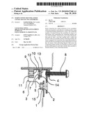
[0017]In FIG. 1, the assembly 1 is shown which is addressed in more detail below with respect to its possible connection. The flange 2 of the connecting member 3 is juxtaposed to assembly 1, which member furthermore consists out of the mother piece 4 and the web 5 which is connected to the mother piece 4 by the wall 6. Consequently, the connecting member 3 consists out of the flange 2, the mother piece 4, the wall 6 and the web 5. The mother piece 4 and the web 5 each comprise a bore (see bore 7) where the self-cutting screw 8 is screwed into the bore penetrating the mother piece 4.
[0018]Juxtaposed to the connecting member 3 is the second assembly 9 which extends long the connecting member 3 with the bottom 10 to which the mother piece 11 is mounted. The mother piece 11 comprises the bore 12 which, in the assembled position shown in FIG. 1 of the connecting member 3 and the two assemblies 2 and 11, is coaxial with the bores 12 and 13 in the assembly 2 and bore 7 in the web 5 and is coaxially aliened with the bore in the mother piece 4 penetrated by the screw 8. The extension 14 which extends approximately parallel to the web 5 of the connecting member 3 and is provided with a hole 13 coaxial with the hole 7, extends away from the bottom 10 of the assembly 9. FIG. 1 shows, furthermore, the welded nut 15 of the assembly 1 which ultimately is to be connected to the assembly 9 by means of the connecting member 3.
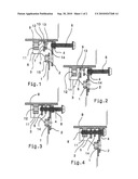
[0019]FIG. 2 shows the starting phase of mounting the two assemblies 1 and 9 by means of the connecting member 3, whereby a position of the connecting member 3 is obtained in which the flange 2 thereof is abutting the assembly 1, and the web 5 of the connecting member 3 has moved more close to the mother piece 11. As can be seen, the bore containing the screw 8 as well as the further bores 13, 7 and 12 are coaxially aliened.
[0020]In order to securely connect the two assemblies 1 and 9 with each other by means of the connecting member, the screw 8 is now further screwed into the assembly 9 and into the connecting member 3, whereby, at first, the position shown in FIG. 3 obtained in which the screw 8 penetrates the bore in the mother piece 4 and bores 13 and 7, whereby the screw 8 has grooved a thread in each of the penetrated parts which results in that, by means of the thread of the screw 8, the parts each surrounding the screw are held axially in a defined distance by means of the thread of the screw 8. The connecting member 3 and the assembly 9 consists out of a material which allows the thread grooving, i.e. plastics or appropriately formable metal for example.
[0021]The last phase of the production of the connection which is shown in FIG. 4 is now following in which the screw 8 is further screwed into the connecting member 3 and the assembly 9, whereby the screw 8 finally completely penetrates also the mother piece 11 of the assembly 9. By means of the screw 8 and the thread grooved thereby, there now exists a fixed connection between the mother piece 4 of the connecting member 3 through the extension 14 and the web 5 up to the mother piece 11. These parts penetrated in such a way by the self-cutting screw 8, are held by means of the thread of the screw 8 in their spacing which is assured by the thread grooved by the screw 8 in the respective parts. Therefore, a secure connection between the assembly 1 and the assembly 9 exists by means of the connecting member 3 which is now undisplaceably held by means of the thread of the self-cutting screw 8.
[0022]Now, the assembly 1 may be fixed to the flange 2, as shown in FIG. 5, by means of the screw 16. In FIG. 5, the headlight 27 as assembly 9 and the car body 28 as assembly 1 of an automobile are shown as examples.
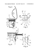
[0023]In FIG. 6, a modification of the arrangement according to the FIGS. 1 to 5 is shown which is about the fact that the connecting member 17 as well as the assembly 18 are interlaced by means of webs 19, 20 and projections 21, 22 in order to achieve a particularly secure, axial anchoring of the two assemblies. This is achieved here thereby that the connecting member 17 comprises two webs 19 and 20, and the second assembly 18 comprises two projections 21 and 22. By means of this interlacing, it is achieved that plural mounting points are present for the respective fixation of two assemblies 1 and 18, when the screw 23 is completely screwed there through.
[0024]In the FIGS. 7 and 8, the connecting member 3 is shown alone, where FIG. 8 shows a section along the line VIII-VIII of FIG. 7.
[0025]The connecting member 3 according to FIG. 7 contains the flange 2 which is connected to the mother piece 4. The two holes 6 and 6' start from flange 2 (in the FIGS. 1 to 5 only the wall 6 is to be seen because of the sectional view), which walls enclose the web 5 between each other. The extension 14 which is not shown in FIG. 7, extends into the free space 24 in the combination of the FIGS. 1 to 5. The two walls 6 and 6' comprise the step 25 and 25' respectively, as can clearly seen from FIG. 8. The mother piece 4, the flange 2 and the web 5 are penetrated each by a bore which is shown in broken lines into which bore, thereafter, upon assembly, the self-cutting screw is screwed in, as is shown in FIGS. 4 to 6.
[0026]It is apparent from the sectional view according to FIG. 8, that the wall 6 supports the web 5 with bore 7, and that the mother piece 4 with the flange 2 is penetrated by a bore which is coaxially aligned with the bore 7. As shown by FIGS. 1 to 5, the two bores are, thereafter, be penetrated by the screw 8 later on upon assembling. The hole 26 contained in the flange 2, serves to take up a screw in order to fix, thereby, a further assembly to the flange 2. As concerns the mounting of such a screw 16, it is pointed to the view in FIG. 5.
Claims:
1. Screw connection for a fixed connection of two assemblies which are
mounted to each other in a variable position, using a connecting member
penetrated by a screw, wherein the connecting member is mounted between
the assemblies by means of a self-cutting screw penetrating the
connecting member and one of the assemblies;the screw is grooving its
thread into both parts in such a way that, starting from a stable end
position of the one assembly and the connecting member, the screw is
adapted to be screwed into the connecting member as well as into the one
assembly by means of thread grooves;by means of the self-cutting thread
of the screw, the connecting member and the one assembly are held in a
fixed position with respect to each other; andthe other assembly is
fastened directly to the connecting member.
2. Screw connection according to claim 1, wherein the connecting member and the one assembly are provided with projections each which comprise coaxial bores for taking up of the screw which is adapted to be coaxially screwed into the bores such that the screw screwed into the bores secures the assembly and the connecting member in the position being obtained during screwing-in.
3. Screw connection according to claim 1, wherein the connecting member and the one assembly, respectively, are provided each with several projections provided with a bore.
Description:
[0001]The invention relates to a screw connection for a fixed connection
of two assemblies which are mounted in a variable position with respect
to each other, using a connecting member penetrated by a screw.
[0002]Making a fixed connection of two assemblies is frequently encountered, in particular in the area of the production of furniture where furniture parts, in particular those which meat each other at right angels, are to be brought into engagement with each other, wherein a fixed connection is established by means of screws. Therein, the problem is frequently encountered that, because of inaccuracies during production, the respective receiving portions for screws, i.e. a hole for a screw head and a bore for a screw thread, are positioned not coaxially to each other such that is necessary to provide for a possibility for correction. In most cases, this is achieved thereby that a seat serving for receiving a connecting screw, for a cheese head of a screw is embraced with clearance whereby a corresponding possibility for correction is given for a connecting member connecting two furniture parts (here DE Utility Model G 88 10 628.4, page 3, first paragraph).
[0003]However, such a possibility for correction proofs to be unfeasible when the two parts to be connected to each other, are subjected to vibrations during use such that they tend to be displaced with respect to each other which results in that the respective fastening means can migrate backwards and forwards in the enlarged receiving hole. Such a possibility of correction is unfeasible for many purposes, in particular in automobile construction where particular assemblies are to be fixed separately to the car body wherein production in accuracies have to be accepted for the car body as well as for the respective assemblies, but where, in spite of this, a connection has to guarantee a stable, undisplaceable seat in the end.
[0004]This problem is solved in a screw connection for a fixed connection of two assemblies which are mounted to each other in a variable position, using a connecting member penetrated by a screw, thereby that the connecting member is mounted between the assemblies by means of a self-cutting screw penetrating the connecting member and one of the assemblies, which screw is grooving its thread into both parts in such a way that, starting from a stable end position of the one assembly and the connecting member, the screw is adapted to be screwed into the connecting member as well as into the one assembly by means of thread grooves such that, by means of the self-cutting thread of the screw, the connecting member and the one assembly are held in a fixed position with respect to each other, and the other assembly is fastened directly to the connecting member.
[0005]In this arrangement, the property of the self-cutting screw to maintained the in the beginning variable, after screwing in of the screw, however, then fixed distance, since two assemblies are provided with a thread by self-cutting upon screwing in of the screw in its given position, respectively, such that, by means of the thread and the screw, the two assemblies are held undisplaceable in the position in which the assembling of the assemblies is such that, also after assembling the two assemblies, they are consequently held stably in their position taken during screwing-in of the screw. Such a connecting member is adapted to be appropriately designed such that the connecting member and the one assembly are provided with protrusions each of which comprise coaxial bores for taking up of the screw which is adapted to be coaxially screwed into the bores such that the screw screwed into the bores secures the assembly and the connecting member in the position being obtained during screwing-in.
[0006]By screwing in the self-cutting screw into the coaxial bores in the two assemblies, the above-mentioned effect of securing the distance of the two assemblies is than resulting since the thread cut therein provides, by means of the screw, a connection which results from the respective position of the assemblies when they are fixed somewhere and are provided with a self-cutting screw.
[0007]In an advantages embodiment, the assemblies and the connecting member, respectively, are provided with several protrusions provided with a bore in order to produce a particularly stable, long lasting connection.
[0008]Embodiments of invention are shown in the Figures.
[0009]FIG. 1 shows the connecting member between two assemblies in their starting position.
[0010]FIG. 2 shows the connecting member in a position directly moved to one of the two assemblies.
[0011]FIG. 3 shows the connecting member with a self-cutting screw penetrating the connecting member and the one assembly.
[0012]FIG. 4 shows the connecting member with a self-cuffing screw penetrating the connecting member and one assembly completely.
[0013]FIG. 5 shows the connecting member with the penetrating screw according to FIG. 4 and the second assembly fixed to the connecting member with a screw.
[0014]FIG. 6 shows a modification of the drawing of FIG. 2 with a connecting member being further send out.
[0015]FIG. 7 shows a view of the connecting member alone.
[0016]FIG. 8 shows a section along the line VIII-VIII of FIG. 7.
[0017]In FIG. 1, the assembly 1 is shown which is addressed in more detail below with respect to its possible connection. The flange 2 of the connecting member 3 is juxtaposed to assembly 1, which member furthermore consists out of the mother piece 4 and the web 5 which is connected to the mother piece 4 by the wall 6. Consequently, the connecting member 3 consists out of the flange 2, the mother piece 4, the wall 6 and the web 5. The mother piece 4 and the web 5 each comprise a bore (see bore 7) where the self-cutting screw 8 is screwed into the bore penetrating the mother piece 4.
[0018]Juxtaposed to the connecting member 3 is the second assembly 9 which extends long the connecting member 3 with the bottom 10 to which the mother piece 11 is mounted. The mother piece 11 comprises the bore 12 which, in the assembled position shown in FIG. 1 of the connecting member 3 and the two assemblies 2 and 11, is coaxial with the bores 12 and 13 in the assembly 2 and bore 7 in the web 5 and is coaxially aliened with the bore in the mother piece 4 penetrated by the screw 8. The extension 14 which extends approximately parallel to the web 5 of the connecting member 3 and is provided with a hole 13 coaxial with the hole 7, extends away from the bottom 10 of the assembly 9. FIG. 1 shows, furthermore, the welded nut 15 of the assembly 1 which ultimately is to be connected to the assembly 9 by means of the connecting member 3.
[0019]FIG. 2 shows the starting phase of mounting the two assemblies 1 and 9 by means of the connecting member 3, whereby a position of the connecting member 3 is obtained in which the flange 2 thereof is abutting the assembly 1, and the web 5 of the connecting member 3 has moved more close to the mother piece 11. As can be seen, the bore containing the screw 8 as well as the further bores 13, 7 and 12 are coaxially aliened.
[0020]In order to securely connect the two assemblies 1 and 9 with each other by means of the connecting member, the screw 8 is now further screwed into the assembly 9 and into the connecting member 3, whereby, at first, the position shown in FIG. 3 obtained in which the screw 8 penetrates the bore in the mother piece 4 and bores 13 and 7, whereby the screw 8 has grooved a thread in each of the penetrated parts which results in that, by means of the thread of the screw 8, the parts each surrounding the screw are held axially in a defined distance by means of the thread of the screw 8. The connecting member 3 and the assembly 9 consists out of a material which allows the thread grooving, i.e. plastics or appropriately formable metal for example.
[0021]The last phase of the production of the connection which is shown in FIG. 4 is now following in which the screw 8 is further screwed into the connecting member 3 and the assembly 9, whereby the screw 8 finally completely penetrates also the mother piece 11 of the assembly 9. By means of the screw 8 and the thread grooved thereby, there now exists a fixed connection between the mother piece 4 of the connecting member 3 through the extension 14 and the web 5 up to the mother piece 11. These parts penetrated in such a way by the self-cutting screw 8, are held by means of the thread of the screw 8 in their spacing which is assured by the thread grooved by the screw 8 in the respective parts. Therefore, a secure connection between the assembly 1 and the assembly 9 exists by means of the connecting member 3 which is now undisplaceably held by means of the thread of the self-cutting screw 8.
[0022]Now, the assembly 1 may be fixed to the flange 2, as shown in FIG. 5, by means of the screw 16. In FIG. 5, the headlight 27 as assembly 9 and the car body 28 as assembly 1 of an automobile are shown as examples.
[0023]In FIG. 6, a modification of the arrangement according to the FIGS. 1 to 5 is shown which is about the fact that the connecting member 17 as well as the assembly 18 are interlaced by means of webs 19, 20 and projections 21, 22 in order to achieve a particularly secure, axial anchoring of the two assemblies. This is achieved here thereby that the connecting member 17 comprises two webs 19 and 20, and the second assembly 18 comprises two projections 21 and 22. By means of this interlacing, it is achieved that plural mounting points are present for the respective fixation of two assemblies 1 and 18, when the screw 23 is completely screwed there through.
[0024]In the FIGS. 7 and 8, the connecting member 3 is shown alone, where FIG. 8 shows a section along the line VIII-VIII of FIG. 7.
[0025]The connecting member 3 according to FIG. 7 contains the flange 2 which is connected to the mother piece 4. The two holes 6 and 6' start from flange 2 (in the FIGS. 1 to 5 only the wall 6 is to be seen because of the sectional view), which walls enclose the web 5 between each other. The extension 14 which is not shown in FIG. 7, extends into the free space 24 in the combination of the FIGS. 1 to 5. The two walls 6 and 6' comprise the step 25 and 25' respectively, as can clearly seen from FIG. 8. The mother piece 4, the flange 2 and the web 5 are penetrated each by a bore which is shown in broken lines into which bore, thereafter, upon assembly, the self-cutting screw is screwed in, as is shown in FIGS. 4 to 6.
[0026]It is apparent from the sectional view according to FIG. 8, that the wall 6 supports the web 5 with bore 7, and that the mother piece 4 with the flange 2 is penetrated by a bore which is coaxially aligned with the bore 7. As shown by FIGS. 1 to 5, the two bores are, thereafter, be penetrated by the screw 8 later on upon assembling. The hole 26 contained in the flange 2, serves to take up a screw in order to fix, thereby, a further assembly to the flange 2. As concerns the mounting of such a screw 16, it is pointed to the view in FIG. 5.
User Contributions:
Comment about this patent or add new information about this topic:
Images included with this patent application:
 |  |
 |
| Similar patent applications: | |
| Date | Title |
|---|---|
| 2013-03-21 | Anaerobic adhesive and sealant compositions in film form, film spool assemblies containing such compositions in film form and preapplied versions thereof on matable parts |
| 2012-12-20 | Cover for a stud and nut assembly |
| 2012-03-22 | Screw and nut assembly |
| 2013-02-07 | Self locking nut and bolt assembly |
| 2013-02-07 | Screw with helical groove for receiving chippings |
| New patent applications in this class: | |
| Date | Title |
|---|---|
| 2013-11-07 | One piece hydraulic disc brake caliper with one way plumbing |
| 2011-10-27 | Threaded rod |
| New patent applications from these inventors: | |
| Date | Title |
|---|---|
| 2009-12-17 | Self-tapping drill screw |
| Top Inventors for class "Expanded, threaded, driven, headed, tool-deformed, or locked-threaded fastener" | |
| Rank | Inventor's name |
|---|---|
| 1 | Jiri Babej |
| 2 | Luke Haylock |
| 3 | Richard Humpert |
| 4 | Jacob Olsen |
| 5 | Paul Gaudron |