Patent application title: Sander Having a Brushless Motor
Inventors:
Uday S. Deshpande (San Diego, CA, US)
Shailesh P. Waikar (Parkville, MD, US)
Madhur M. Purohit (Towson, MD, US)
Paul J. Wisniewski (Baltimore, MD, US)
David W. Wiseman (O'Fallen, MO, US)
IPC8 Class: AB24B2300FI
USPC Class:
451344
Class name: Abrading frame or mount portable abrader
Publication date: 2010-09-23
Patent application number: 20100240286
nd having a proximal end and a distal end, a
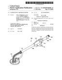
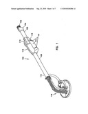
sanding head mounted to the proximal end of the wand, and a brushless
motor mounted on the distal end of the wand that is configured to provide
rotational motion to the sanding head.Claims:
1. A sander comprising:a wand having a proximal end and a distal end;a
sanding head mounted to the proximal end of the wand; anda brushless
motor mounted on the distal end of the wand that is configured to provide
rotational motion to the sanding head.
2. The sander of claim 1 wherein the brushless motor is a direct current (DC) brushless motor.
3. The sander of claim 1 wherein the brushless motor is an alternating current (AC) brushless motor.
4. The sander of claim 1 wherein the sanding head is mounted by a pivotal joint to the proximal end of the wand.
5. The sander of claim 1 further comprising a drive shaft extending a length of the wand that is coupled to the sanding head and the brushless motor.
6. The sander of claim 1 further comprising a motor housing enclosing one or more components of the brushless motor.
7. The sander of claim 6 further comprising a fan mounted external to the motor housing.
8. The sander of claim 6 further comprising a sander housing having at least one vent and substantially enclosing the motor housing.Description:
CROSS REFERENCE TO RELATED APPLICATION
[0001]This application claims the benefit of U.S. Provisional Patent Application Ser. No. 60/763,961, filed on Feb. 1, 2006, and titled "Sander Having A Brushless Motor", which is incorporated by reference in its entirety.
TECHNICAL FIELD
[0002]This description relates to a motorized sander having a brushless motor.
BACKGROUND
[0003]A motorized sander may be used to remove material from various types of surfaces. For instance, the motorized sander may be used to remove material from drywall surfaces, concrete surfaces, wood surfaces, and other surfaces. Additionally, the motorized sander also may be used for scuffing or roughing up a painted surface prior to applying another coat of paint. In addition, it may be used as a floor buffer, a device for removing barnacles on fiberglass boats, removing textures on a ceiling, wallpaper, and wallpaper paste as well as other assorted planar surface sanding operations. During the removal process, the environment may become contaminated. For example, when removing joint compound from a drywall surface, the environment may become contaminated with dust and other contaminants. Motorized sanders that include brush-type motors may run continuously for long periods of time in environments that contain high levels of contaminants. In a brush-type motor, the motor housing typically includes a fan within the motor housing to cool the stator and the rotor by providing air flow within the motor housing. The dust and other contaminants are constantly being circulated through the air stream of the brush-type motor which may result in frequent brush changes and low overall tool life, both of which may cause frequent down time and lost productivity for the user.
DESCRIPTION OF DRAWINGS
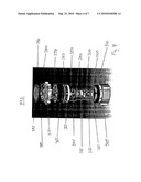
[0004]FIG. 1 is an isometric view of an exemplary motorized sander.
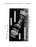
[0005]FIG. 2 is an exemplary cut-away view of a housing with an installed brushless motor.
[0006]FIG. 3 is an assembled view of an exemplary brushless motor.
[0007]FIG. 4 is an exploded view of an exemplary brushless motor.
[0008]FIG. 5 is an exploded view of an exemplary brushless motor.
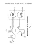
[0009]FIG. 6 is an exemplary schematic wiring diagram.
[0010]FIG. 7 is an isometric view of an exemplary electronic control module.
[0011]Like reference symbols in the various drawings indicate like elements.
DETAILED DESCRIPTION
[0012]In one exemplary implementation, a motorized sander includes a brushless motor. The brushless motor may include a brushless direct current (DC) motor or a brushless alternating current (AC) motor. In a brushless motor, the rotation of the rotor is produced and controlled without the use of one or more high wear components such as, for example, the brushes and a commutator. Additionally, one or more of the brushless motor components may be enclosed and/or sealed within a motor housing or a motor pack. The motor housing or motor pack may not include a fan within the motor housing or the motor pack and thus, there would be no air flow within the motor housing or motor pack. This would eliminate the dust and other contaminants from being circulated within the motor housing or motor pack. To provide cooling for the motor housing or the motor pack, a fan may be connected external to the motor housing or motor pack and provide air flow over the motor housing or motor pack but not within the motor housing or motor pack.
[0013]Provided below is an exemplary description one or more implementations of a brushless motor in a motorized sander. The exemplary description is not meant to be limited to a specific type of sander. Instead, the brushless motor also may be implemented in other types of motorized sanders.
[0014]Referring to FIG. 1, a motorized sander 100 may include a hose clamp nut 102 attached to a vacuum adapter housing set 104 which in turn may be attached to a distal end 106 of a dual chamber tubular wand 108. The tubular wand 108 also may include a proximal end 110.
[0015]In one exemplary implementation, the motorized sander 100 may include a housing 112 that houses a brushless motor 113. The housing 112 may include one or more air vents 117 to enable air flow through the housing and around the motor pack of the brushless motor 113. The brushless motor 113 may be coupled in-line with the tubular wand 108. The brushless motor 113 may be mounted at the distal end 106 so that sander 100 has a balancing point near the middle of the length of tubular wand 108 when a sanding head 118 is attached to the proximal end 110. The brushless motor 113 may be a variable speed brushless motor. The brushless motor 113 includes an on/off toggle switch 114. In one implementation, the motor speed may be varied by a variable speed thumb wheel switch 116 located on the opposite side of the tubular wand 108 from the on/off switch 114.
[0016]The dual chamber tubular wand 108 may include a first lower chamber and a second upper chamber which extend along the length of the tubular wand 108. A flexible drive shaft within the tubular wand 108 may be coupled to the brushless motor 113 and extend along the length of tubular wand 108 towards the proximal end 110 within the first chamber. The flexible drive shaft may receive rotational energy from the brushless motor 113 and impart the rotational energy to the sanding head 118. A vacuum line may extend through the second chamber from the proximal end 110 to the distal end 106 to the vacuum hose clamp 102. This vacuum line within the second chamber may be completely separate and sealed from the first chamber of the tubular wand as well as being sealed from the brushless motor 113.
[0017]The sanding head 118 may be mounted by a pivotal joint to the proximal end 110 of the tubular wand 108. The sanding head 118 may include a sanding drive plate that is coupled to the flexible drive shaft. The flexible drive shaft may not be securely fastened to the sanding drive plate, but rather may be loosely fit into a slotted drive hole within a threaded spindle which allows the flexible drive shaft to move back and forth between the sanding head 118 and the brushless motor 113 as the sanding head 118 is pivoted/bent into various positions. The pivotal joint may include a first flexible joint and a second flexible joint. The first joint may be configured to pivot about a first axis which is different from a second axis about which the second joint pivots. In one exemplary implementation, the first axis is perpendicular to the second axis.
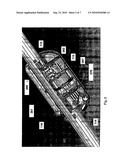
[0018]Referring to FIG. 2, a cut-away view of an exemplary housing 112 is illustrated. The housing 112 is in-line with the tubular wand 108. The housing 112 houses the brushless motor 113. The housing 112 includes one or more air vents 117 to provide air flow to cool the brushless motor 113. In one exemplary implementation, the power on/off switch 114 and the variable speed switch 116 may be connected to the housing 112 with internal connections to components within the housing 112.
[0019]The output of the brushless motor 113 may be connected to one or more gears 261, which may be enclosed by a gear case cover 262. The gears may be connected to an output shaft 265 that provides rotational energy through the flexible drive shaft to the sanding head assembly. The housing may include a baffle 267 to direct air flow over the brushless motor 113. The brushless motor 113 also may be connected to a capacitor 270.
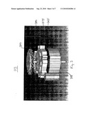
[0020]Referring to FIGS. 3-5, exemplary views of the brushless motor 113 are illustrated. The brushless motor 113 includes a housing 305 that encloses the stator and rotor subassemblies. The stator sub assembly includes the stack 310 and windings 315. Laminations may be bonded together and then coated with insulating material. In one exemplary implementation, the stack 310 may be a 20 mm stack length. The windings 315 are wound over the stack 310. The stator sub assembly may be press fit inside the housing 305.
[0021]The rotor sub assembly includes a bottom bearing 320, shaft 325, one or more rotor magnets 330, rotor 335, sense magnet tray 340, one or more sense magnets 345 and a top bearing 350. The bottom bearing 320 may be press fit on the shaft 325. The rotor 335 may be press fit on the shaft 325 from the other side and the rotor magnets 330 may be glued to the sense magnet tray 340. The top bearing 350 may be press fitted on the shaft 325. The bottom bearing 320 may be push fitted inside a bearing pocket of the housing 305.
[0022]The stack 310 and windings 315 enclose the rotor sub assembly providing a rotating magnetic field that the rotor sub assembly magnetic field is drawn towards. The bottom bearing 320 and the top bearing 350 provide a mechanical interface to permit rotation of the rotor sub assembly.
[0023]The sense magnets 345 may provide a marker of the relative position of the windings 315. A sensor card 360, which may be connected to a sensor card spacer 355, may include multiple Hall sensors that are spaced apart to detect the sensor magnets 345 as the shaft 325 rotates.
[0024]A motor spacer 365 may separate rotor and stator sub assemblies from an electronic control module 370, an electronics end cap 375, a bushing 370, and a fan 390. The electronic control module 370 may include one or more components to that may be configured to control the rotor and stator sub assemblies. The electronic control module 370 may include a wire holder 380. The electronic control module 370 may be potted. One or more fasteners 395 may be used to fasten one or more components of the brushless motor 113 together. The fasteners 395 may be used to stop the axial movement of the fan 390.
[0025]FIGS. 5 and 6 illustrate the electrical connections within the brushless motor 113. An electrical connection is made from the windings 315 to the electronic control module 370 and from the Hall sensors on the sensor board 360 to the electronic control module 370. The switch 114, speed control 116, capacitor 270, and power supply 605 also may be electrically connected to the electronic control module 370.
[0026]FIG. 7 illustrates the electronic control module 370 that is electrically connected to capacitor 270 and includes multiple electronic control components including, for example, MosFETs 770.
[0027]Other implementations are within the scope of the following claims.
Claims:
1. A sander comprising:a wand having a proximal end and a distal end;a
sanding head mounted to the proximal end of the wand; anda brushless
motor mounted on the distal end of the wand that is configured to provide
rotational motion to the sanding head.
2. The sander of claim 1 wherein the brushless motor is a direct current (DC) brushless motor.
3. The sander of claim 1 wherein the brushless motor is an alternating current (AC) brushless motor.
4. The sander of claim 1 wherein the sanding head is mounted by a pivotal joint to the proximal end of the wand.
5. The sander of claim 1 further comprising a drive shaft extending a length of the wand that is coupled to the sanding head and the brushless motor.
6. The sander of claim 1 further comprising a motor housing enclosing one or more components of the brushless motor.
7. The sander of claim 6 further comprising a fan mounted external to the motor housing.
8. The sander of claim 6 further comprising a sander housing having at least one vent and substantially enclosing the motor housing.
Description:
CROSS REFERENCE TO RELATED APPLICATION
[0001]This application claims the benefit of U.S. Provisional Patent Application Ser. No. 60/763,961, filed on Feb. 1, 2006, and titled "Sander Having A Brushless Motor", which is incorporated by reference in its entirety.
TECHNICAL FIELD
[0002]This description relates to a motorized sander having a brushless motor.
BACKGROUND
[0003]A motorized sander may be used to remove material from various types of surfaces. For instance, the motorized sander may be used to remove material from drywall surfaces, concrete surfaces, wood surfaces, and other surfaces. Additionally, the motorized sander also may be used for scuffing or roughing up a painted surface prior to applying another coat of paint. In addition, it may be used as a floor buffer, a device for removing barnacles on fiberglass boats, removing textures on a ceiling, wallpaper, and wallpaper paste as well as other assorted planar surface sanding operations. During the removal process, the environment may become contaminated. For example, when removing joint compound from a drywall surface, the environment may become contaminated with dust and other contaminants. Motorized sanders that include brush-type motors may run continuously for long periods of time in environments that contain high levels of contaminants. In a brush-type motor, the motor housing typically includes a fan within the motor housing to cool the stator and the rotor by providing air flow within the motor housing. The dust and other contaminants are constantly being circulated through the air stream of the brush-type motor which may result in frequent brush changes and low overall tool life, both of which may cause frequent down time and lost productivity for the user.
DESCRIPTION OF DRAWINGS
[0004]FIG. 1 is an isometric view of an exemplary motorized sander.
[0005]FIG. 2 is an exemplary cut-away view of a housing with an installed brushless motor.
[0006]FIG. 3 is an assembled view of an exemplary brushless motor.
[0007]FIG. 4 is an exploded view of an exemplary brushless motor.
[0008]FIG. 5 is an exploded view of an exemplary brushless motor.
[0009]FIG. 6 is an exemplary schematic wiring diagram.
[0010]FIG. 7 is an isometric view of an exemplary electronic control module.
[0011]Like reference symbols in the various drawings indicate like elements.
DETAILED DESCRIPTION
[0012]In one exemplary implementation, a motorized sander includes a brushless motor. The brushless motor may include a brushless direct current (DC) motor or a brushless alternating current (AC) motor. In a brushless motor, the rotation of the rotor is produced and controlled without the use of one or more high wear components such as, for example, the brushes and a commutator. Additionally, one or more of the brushless motor components may be enclosed and/or sealed within a motor housing or a motor pack. The motor housing or motor pack may not include a fan within the motor housing or the motor pack and thus, there would be no air flow within the motor housing or motor pack. This would eliminate the dust and other contaminants from being circulated within the motor housing or motor pack. To provide cooling for the motor housing or the motor pack, a fan may be connected external to the motor housing or motor pack and provide air flow over the motor housing or motor pack but not within the motor housing or motor pack.
[0013]Provided below is an exemplary description one or more implementations of a brushless motor in a motorized sander. The exemplary description is not meant to be limited to a specific type of sander. Instead, the brushless motor also may be implemented in other types of motorized sanders.
[0014]Referring to FIG. 1, a motorized sander 100 may include a hose clamp nut 102 attached to a vacuum adapter housing set 104 which in turn may be attached to a distal end 106 of a dual chamber tubular wand 108. The tubular wand 108 also may include a proximal end 110.
[0015]In one exemplary implementation, the motorized sander 100 may include a housing 112 that houses a brushless motor 113. The housing 112 may include one or more air vents 117 to enable air flow through the housing and around the motor pack of the brushless motor 113. The brushless motor 113 may be coupled in-line with the tubular wand 108. The brushless motor 113 may be mounted at the distal end 106 so that sander 100 has a balancing point near the middle of the length of tubular wand 108 when a sanding head 118 is attached to the proximal end 110. The brushless motor 113 may be a variable speed brushless motor. The brushless motor 113 includes an on/off toggle switch 114. In one implementation, the motor speed may be varied by a variable speed thumb wheel switch 116 located on the opposite side of the tubular wand 108 from the on/off switch 114.
[0016]The dual chamber tubular wand 108 may include a first lower chamber and a second upper chamber which extend along the length of the tubular wand 108. A flexible drive shaft within the tubular wand 108 may be coupled to the brushless motor 113 and extend along the length of tubular wand 108 towards the proximal end 110 within the first chamber. The flexible drive shaft may receive rotational energy from the brushless motor 113 and impart the rotational energy to the sanding head 118. A vacuum line may extend through the second chamber from the proximal end 110 to the distal end 106 to the vacuum hose clamp 102. This vacuum line within the second chamber may be completely separate and sealed from the first chamber of the tubular wand as well as being sealed from the brushless motor 113.
[0017]The sanding head 118 may be mounted by a pivotal joint to the proximal end 110 of the tubular wand 108. The sanding head 118 may include a sanding drive plate that is coupled to the flexible drive shaft. The flexible drive shaft may not be securely fastened to the sanding drive plate, but rather may be loosely fit into a slotted drive hole within a threaded spindle which allows the flexible drive shaft to move back and forth between the sanding head 118 and the brushless motor 113 as the sanding head 118 is pivoted/bent into various positions. The pivotal joint may include a first flexible joint and a second flexible joint. The first joint may be configured to pivot about a first axis which is different from a second axis about which the second joint pivots. In one exemplary implementation, the first axis is perpendicular to the second axis.
[0018]Referring to FIG. 2, a cut-away view of an exemplary housing 112 is illustrated. The housing 112 is in-line with the tubular wand 108. The housing 112 houses the brushless motor 113. The housing 112 includes one or more air vents 117 to provide air flow to cool the brushless motor 113. In one exemplary implementation, the power on/off switch 114 and the variable speed switch 116 may be connected to the housing 112 with internal connections to components within the housing 112.
[0019]The output of the brushless motor 113 may be connected to one or more gears 261, which may be enclosed by a gear case cover 262. The gears may be connected to an output shaft 265 that provides rotational energy through the flexible drive shaft to the sanding head assembly. The housing may include a baffle 267 to direct air flow over the brushless motor 113. The brushless motor 113 also may be connected to a capacitor 270.
[0020]Referring to FIGS. 3-5, exemplary views of the brushless motor 113 are illustrated. The brushless motor 113 includes a housing 305 that encloses the stator and rotor subassemblies. The stator sub assembly includes the stack 310 and windings 315. Laminations may be bonded together and then coated with insulating material. In one exemplary implementation, the stack 310 may be a 20 mm stack length. The windings 315 are wound over the stack 310. The stator sub assembly may be press fit inside the housing 305.
[0021]The rotor sub assembly includes a bottom bearing 320, shaft 325, one or more rotor magnets 330, rotor 335, sense magnet tray 340, one or more sense magnets 345 and a top bearing 350. The bottom bearing 320 may be press fit on the shaft 325. The rotor 335 may be press fit on the shaft 325 from the other side and the rotor magnets 330 may be glued to the sense magnet tray 340. The top bearing 350 may be press fitted on the shaft 325. The bottom bearing 320 may be push fitted inside a bearing pocket of the housing 305.
[0022]The stack 310 and windings 315 enclose the rotor sub assembly providing a rotating magnetic field that the rotor sub assembly magnetic field is drawn towards. The bottom bearing 320 and the top bearing 350 provide a mechanical interface to permit rotation of the rotor sub assembly.
[0023]The sense magnets 345 may provide a marker of the relative position of the windings 315. A sensor card 360, which may be connected to a sensor card spacer 355, may include multiple Hall sensors that are spaced apart to detect the sensor magnets 345 as the shaft 325 rotates.
[0024]A motor spacer 365 may separate rotor and stator sub assemblies from an electronic control module 370, an electronics end cap 375, a bushing 370, and a fan 390. The electronic control module 370 may include one or more components to that may be configured to control the rotor and stator sub assemblies. The electronic control module 370 may include a wire holder 380. The electronic control module 370 may be potted. One or more fasteners 395 may be used to fasten one or more components of the brushless motor 113 together. The fasteners 395 may be used to stop the axial movement of the fan 390.
[0025]FIGS. 5 and 6 illustrate the electrical connections within the brushless motor 113. An electrical connection is made from the windings 315 to the electronic control module 370 and from the Hall sensors on the sensor board 360 to the electronic control module 370. The switch 114, speed control 116, capacitor 270, and power supply 605 also may be electrically connected to the electronic control module 370.
[0026]FIG. 7 illustrates the electronic control module 370 that is electrically connected to capacitor 270 and includes multiple electronic control components including, for example, MosFETs 770.
[0027]Other implementations are within the scope of the following claims.
User Contributions:
Comment about this patent or add new information about this topic:
Images included with this patent application:
 |  |
 |  |
 |  |
 |
| New patent applications in this class: | |
| Date | Title |
|---|---|
| 2016-07-14 | Grinding machine housing device |
| 2016-06-30 | Handheld abrading machine |
| 2016-06-16 | Sanding device, and sanding assembly including the same |
| 2016-05-05 | Hand held and/or hand guided power tool |
| 2016-05-05 | Pneumatic grinding tool |
| New patent applications from these inventors: | |
| Date | Title |
|---|---|
| 2021-11-18 | Brushless motor having an overmolded rotor |
| 2016-02-25 | Portable power supply |
| 2014-05-15 | Control unit for a power tool |
| 2014-04-10 | Power tool hall effect mode selector switch |
| Top Inventors for class "Abrading" | |
| Rank | Inventor's name |
|---|---|
| 1 | Boguslaw A. Swedek |
| 2 | Hung Chih Chen |
| 3 | Jeffrey Drue David |
| 4 | Dominic J. Benvegnu |
| 5 | Chien-Min Sung |