Patent application title: HEAT DISSIPATION DEVICE
Inventors:
Cheng Kong (Shenzhen City, CN)
Hong-Cheng Yang (Shenzhen City, CN)
Assignees:
FU ZHUN PRECISION INDUSTRY (SHEN ZHEN) CO., LTD.
FOXCONN TECHNOLOGY CO., LTD.
IPC8 Class: AF28F700FI
USPC Class:
165121
Class name: Heat exchange with impeller or conveyor moving exchange material mechanical gas pump
Publication date: 2010-09-23
Patent application number: 20100236764
Inventors list |
Agents list |
Assignees list |
List by place |
Classification tree browser |
Top 100 Inventors |
Top 100 Agents |
Top 100 Assignees |
Usenet FAQ Index |
Documents |
Other FAQs |
Patent application title: HEAT DISSIPATION DEVICE
Inventors:
HONG-CHENG YANG
CHENG KONG
Agents:
Altis Law Group, Inc.;ATTN: Steven Reiss
Assignees:
Origin: CITY OF INDUSTRY, CA US
IPC8 Class: AF28F700FI
USPC Class:
Publication date: 09/23/2010
Patent application number: 20100236764
Abstract:
A heat dissipation device includes a heat sink, a fan placed on the heat
sink and two wire clips securing the fan on the heat sink. The heat sink
has two grooves defined in two flanks thereof. The fan has a frame with a
plurality of holes defined therein. Each clip includes an engaging arm
received in a corresponding groove of the heat sink, two tensile parts
extending upwardly from two opposite ends of the engaging arm, two hooks
formed at free ends of the tensile parts and inserted into the holes of
the fan, and a handle protruding from a middle of the engaging arm.Claims:
1. A heat dissipation device comprising:a heat sink;a fan placed on a top
of the heat sink; andtwo wire clips securing the fan on the heat sink,
each of the clips having an engaging arm engaged with the heat sink, two
tensile parts extending upwardly from two opposite ends of the engaging
arm, and two hooks formed at free ends of the tensile parts and engaged
with the fan.
2. The heat dissipation device as claimed in claim 1, wherein the tensile parts and the hooks are symmetric relative to a middle of the engaging arm.
3. The heat dissipation device as claimed in claim 1, wherein each of the clips further has a handle protruding from a middle of the engaging arm.
4. The heat dissipation device as claimed in claim 1, wherein the fan comprises a frame with holes defined therein, and the hooks of the clips are inserted into the holes.
5. The heat dissipation device as claimed in claim 1, wherein the heat sink comprises a base plate and two first fins extending from two flanks of the base plate, and a first horizontal portion extending outwardly from a top end of one of the two first fins, a first perpendicular portion extending upwardly from a free end of the first horizontal portion, a second horizontal portion extending outwardly from a top end of the first perpendicular portion and a second perpendicular portion extending upwardly from a free end of the second horizontal portion, and wherein the fan is located on the second horizontal portions and between the second perpendicular portions, and the engaging arms of the clips engage bottoms of the first horizontal portions.
6. The heat dissipation device as claimed in claim 5, wherein a groove is defined in the bottom of each first horizontal portion for receiving a corresponding engaging arm therein.
7. The heat dissipation device as claimed in claim 5, wherein the heat sink further comprises a plurality of second fins extending from the base plate and between the first fins.
8. The heat dissipation device as claimed in claim 7, wherein the heat sink further comprises a plurality of third fins extending from first horizontal portions.
9. The heat dissipation device as claimed in claim 8, wherein the first, second and third fins are parallel to each other, and tops of the second and third fins are beneath the second horizontal portions.
10. A heat dissipation device comprising:a heat sink having two grooves respectively defined in two flanks thereof;a fan placed on the heat sink, the fan having a frame with a plurality of holes defined therein; andtwo clips securing the fan on the heat sink, each clip comprising an engaging arm received in a corresponding groove of the heat sink, two tensile parts extending from two opposite ends of the engaging arm, two hooks formed at free ends of the tensile parts and inserted into corresponding ones of the holes of the fan, and a handle protruding from a middle of the engaging arm configured for facilitating a manipulation of each clip.
11. The heat dissipation device as claimed in claim 10, wherein the heat sink comprises a base plate, two first fins extending from two flanks of the base plate, a first horizontal portion extending horizontally and outwardly from a top of each first fin, a first perpendicular portion extending upwardly from the first horizontal portion, a second horizontal portion extending horizontally and outwardly from a top of the first perpendicular portion, and a second perpendicular portion extending upwardly from the second horizontal portion, and wherein the grooves are defined in bottoms of the first horizontal portions.
12. The heat dissipation device as claimed in claim 11, wherein the fan is located on the second horizontal portions and between the second perpendicular portions.
13. The heat dissipation device as claimed in claim 11, wherein the heat sink further comprises a plurality of second fins extending from the base plate and between the first fins, and a plurality of third fins extending from the first horizontal portions.
14. The heat dissipation device as claimed in claim 10, wherein the tensile parts are C-shaped and stretched to generate an elastic force to render the engaging arms and hooks respectively engaging with the heat sink and the fan to secure the fan on the heat sink.
Description:
BACKGROUND
[0001]1. Technical Field
[0002]The present disclosure relates generally to a heat dissipation device, and more particularly to a heat dissipation device having a heat sink and fan clips for facilitating a mounting of a fan on the heat sink.
[0003]2. Description of Related Art
[0004]Generally, in order to ensure the normal running of an electronic device, a heat dissipation device is used to dissipate heat generated by the electronic device. A conventional heat dissipation device includes a heat sink and a fan attached on the heat sink to improve a heat-dissipation capacity of the heat sink.
[0005]When installing the fan to the heat sink, it is generally to fix the fan to a side of the heat sink via a fan holder with screws. However, using the screws requires a lot of manpower and material resources. Furthermore, it is necessary to remove the fan at first by unscrewing the screws when disassembling and maintaining the heat dissipation device. Such unscrewing operation is tiresome. In addition, it is also possible that the unscrewed screws fall into a computer in which the heat dissipation device is mounted to cause damages to components of the computer.
[0006]What is need therefore is a heat dissipation device having a design which makes assembling and disassembling of a fan to/from a heat sink of the heat dissipation device be convenient and easy.
BRIEF DESCRIPTION OF THE DRAWINGS
[0007]Many aspects of the present embodiments can be better understood with reference to the following drawings. The components in the drawings are not necessarily drawn to scale, the emphasis instead being placed upon clearly illustrating the principles of the present embodiments. Moreover, in the drawings, like reference numerals designate corresponding parts throughout the several views.
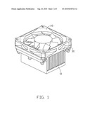
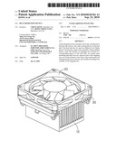
[0008]FIG. 1 is an isometric, assembled view of a heat dissipation device in accordance with an embodiment of the present disclosure.
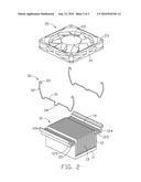
[0009]FIG. 2 is an exploded view of the heat dissipation device of FIG. 1.
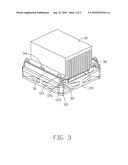
[0010]FIG. 3 is an inverted view of the heat dissipation device of FIG. 1.
DETAILED DESCRIPTION
[0011]FIG. 1 illustrates a heat dissipation device in accordance with an embodiment of the present disclosure. The heat dissipation device dissipates heat from a heat-generating component such as a CPU (not shown). The heat dissipation device comprises a heat sink 10, a fan 20 arranged on a top of the heat sink 10, and two wire clips 30 fastening the fan 20 on the heat sink 10.
[0012]Referring to FIG. 2, the heat sink 10 is integrally formed of a material with a good heat conductivity such as aluminum and copper and comprises a base plate 11 and two first fins 12 extending upwardly from two flanks of the base plate 11. A first horizontal portion 123 extends outwardly and horizontally from a top free end of each first fin 12. A first perpendicular portion 124 extends upwardly from a free end of the first horizontal portion 123. A second horizontal portion 125 extends outwardly and horizontally from a free end of the first perpendicular portion 124. A second perpendicular portion 126 extends upwardly from a free end of the second horizontal portion 125. A groove 121 is defined in a bottom of each first horizontal portion 123 and parallel to the first fins 12. The grooves 121 and the first horizontal portions 123 have a same length. The heat sink 10 further comprises a plurality of second fins 13 extending upwardly from the base plate 11 and between the two first fins 12, and a plurality of third fins 14 extending upwardly from the first horizontal portions 123. The first, second and third fins 12, 13, 14 are parallel to each other. Tops of the second and third fins 13, 14 are beneath the second horizontal portions 125.
[0013]In the present embodiment, the third fins 14 extend upwardly from the first horizontal portions 123. Understandably, in an alternative embodiment, the third fins 14 can further include fins or be fins extending downwardly from the first horizontal portions 123.
[0014]Each wire clip 30 is integrally formed by bending an elastic metallic wire and comprises a straight engaging arm 31, two tensile parts 32, two hooks 33 and a handle 34. The tensile parts 32 extend upwardly from two opposite ends of the engaging arm 31. The tensile parts 32 are substantially C-shaped and can be stretched to generate an elastic force. Each of the hooks 33 bends inwardly from a free end of each tensile part 32. A middle of the engaging arm 31 bends and protrudes downwardly to form the handle 34. The handle 34 is substantially U-shaped. The tensile parts 32 and the hooks 33 are symmetric relative to the handle 34.
[0015]The fan 20 comprises a frame 21 and an impeller 22 rotatably received in the frame 21. Four holes 23 are defined in four corners of the fan frame 21.
[0016]Also referring to FIG. 3, in assembly, the fan 20 is located on the second horizontal portions 125 and sandwiched between the second perpendicular portions 126. The second perpendicular portions 126 restrict the movement of the fan 20 along a lateral direction of the heat sink 10. The hooks 33 are inserted into the holes 23 of the fan 20. Then, the handle 34 is pulled downwardly to stretch the tensile parts 32 until the engaging arm 31 is aligned with the groove 121 of the heat sink 10. The pulling force on the handle 34 thereafter is released to cause the engaging arm 31 to enter and tightly engage in the groove 121 of the heat sink 10. The tensile parts 32 restrict the movement of the fan 20 along rear-to-front of the heat sink 10, and the engaging arms 31 and hooks 33 restrict the movement of the fan 20 along a vertical direction of the heat sink 10. Thus, the fan 20 is secured on the heat sink 10.
[0017]A detachment of the fan 20 from the heat sink 10 can be easily achieved by directly pulling the handle 34 downwardly and outwardly to disengage the engaging arm 31 of each clip 30 from the groove 121 of the heat sink 10. Thereafter, the handle 34 is rotated outwardly and upwardly to completely release the locking between the clip 30 and the heat sink 10.
[0018]It is believed that the present embodiments and their advantages will be understood from the foregoing description, and it will be apparent that various changes may be made thereto without departing from the spirit and scope of the disclosure or sacrificing all of its material advantages, the examples hereinbefore described merely being preferred or exemplary embodiments of the disclosure.
User Contributions:
comments("1"); ?> comment_form("1"); ?>Inventors list |
Agents list |
Assignees list |
List by place |
Classification tree browser |
Top 100 Inventors |
Top 100 Agents |
Top 100 Assignees |
Usenet FAQ Index |
Documents |
Other FAQs |
User Contributions:
Comment about this patent or add new information about this topic:
Images included with this patent application:
 |  |
 |  |
| Similar patent applications: | |
| Date | Title |
|---|---|
| 2010-06-24 | Heat dissipation device |
| 2010-08-05 | Heat dissipation device |
| 2010-08-19 | Heat dissipation device |
| 2010-08-26 | Heat dissipation device |
| 2010-09-23 | Heat dissipation device |
| New patent applications in this class: | |
| Date | Title |
|---|---|
| 2016-09-01 | Motor and drive arrangement for refrigeration system |
| 2016-06-23 | Outdoor device for an air conditioner |
| 2016-06-16 | Heat dissipation device and heat dissipation system |
| 2016-06-09 | Heat exchanger assembly |
| 2016-05-26 | Radiator having air guide for preventing heat damage in a vehicle |
| New patent applications from these inventors: | |
| Date | Title |
|---|---|
| 2011-06-30 | Locking structure and method for manufacturing the same and heat dissipation device using the same |
| 2011-06-23 | Heat dissipation device |
| 2010-12-09 | Heat dissipation device and method of manufacturing the same |
| 2010-11-25 | Heat dissipation device having a fan thereon |
| Top Inventors for class "Heat exchange" | |
| Rank | Inventor's name |
|---|---|
| 1 | Levi A. Campbell |
| 2 | Chun-Chi Chen |
| 3 | Tai-Her Yang |
| 4 | Robert E. Simons |
| 5 | Richard C. Chu |