Patent application title: ADJUSTABLE FASTENER
Inventors:
Bin Dai (Shenzhen City, CN)
Assignees:
HONG FU JIN PRECISION INDUSTRY (ShenZhen) CO., LTD.
HON HAI PRECISION INDUSTRY CO., LTD.
IPC8 Class: AF16B3700FI
USPC Class:
411432
Class name: Expanded, threaded, driven, headed, tool-deformed, or locked-threaded fastener internally threaded fastener element, e.g., nut, etc. multipart
Publication date: 2010-05-13
Patent application number: 20100119328
Inventors list |
Agents list |
Assignees list |
List by place |
Classification tree browser |
Top 100 Inventors |
Top 100 Agents |
Top 100 Assignees |
Usenet FAQ Index |
Documents |
Other FAQs |
Patent application title: ADJUSTABLE FASTENER
Inventors:
BIN DAI
Agents:
PCE INDUSTRY, INC.;ATT. Steven Reiss
Assignees:
HONG FU JIN PRECISION INDUSTRY (ShenZhen) CO., LTD.
Origin: CITY OF INDUSTRY, CA US
IPC8 Class: AF16B3700FI
USPC Class:
411432
Publication date: 05/13/2010
Patent application number: 20100119328
Abstract:
An adjustable fastener includes a main body and an elastic portion. The
elastic portion is connected to an end of the main body. The elastic
portion is deformable thus changing a total length of the adjustable
fastener.Claims:
1. An adjustable fastener, comprising:a main body; andan elastic portion
connected to an end of the main body; wherein the elastic portion is
deformable thus changing a total length of the adjustable fastener.
2. The adjustable fastener of claim 1, wherein the adjustable fastener further comprises a flange formed at end of the main body opposite to the elastic portion.
3. The adjustable fastener of claim 2, wherein the main body defines a neck groove in an end adjacent to the flange.
4. The adjustable fastener of claim 1, wherein the main body forms an attaching portion at an end adjacent to the elastic portion, the elastic portion forms a sleeving portion at an end; the attaching portion of the main body and the sleeving portion of the elastic portion are firmly engaged with each other.
5. The adjustable fastener of claim 1, wherein the main body defines a threaded engaging hole.
6. The adjustable fastener of claim 5, wherein the main body further defines a receiving hole communicating with the threaded engaging hole; the elastic portion defines an extending hole communicating with the receiving hole of the main body.
7. The adjustable fastener of claim 1, wherein the adjustable fastener further includes a supporting end positioned at an end of the elastic portion, the supporting end and the main body are at opposite ends of the elastic portion.
8. The adjustable fastener of claim 7, wherein the elastic portion forms a sleeving portion adjacent to the supporting end and the supporting end forms an attaching portion engaging with the sleeving portion of the elastic portion.
9. An adjustable fastener configured for connecting two components, comprising:a main body; anda deformable elastic portion connected to an end of the main body; wherein the two components are located at opposite sides of the elastic portion, thus a distance between the two components is adjustable due to the deformable elastic portion.
10. The adjustable fastener of claim 9, wherein the adjustable fastener further comprises a flange formed at end of the main body opposite to the elastic portion.
11. The adjustable fastener of claim 10, wherein the main body defines a neck groove in an end adjacent to the flange.
12. The adjustable fastener of claim 9, wherein the main body forms an attaching portion at an end adjacent to the elastic portion, the elastic portion forms a sleeving portion at an end; the attaching portion of the main body and the sleeving portion of the elastic portion are firmly engaged with each other.
13. The adjustable fastener of claim 9, wherein the main body defines a threaded engaging hole.
14. The adjustable fastener of claim 9, wherein the adjustable fastener further includes a supporting end positioned at an end of the elastic portion, the supporting end and the main body are at opposite ends of the elastic portion.
15. The adjustable fastener of claim 14, wherein the elastic portion forms a sleeving portion adjacent to the supporting end and the supporting end forms an attaching portion engaging with the sleeving portion of the elastic portion.
Description:
BACKGROUND
[0001]1. Technical Field
[0002]The present disclosure generally relates to fasteners and, particularly, to an adjustable fastener with a threaded portion.
[0003]2. Description of Related Art
[0004]Fasteners connect two or more components together. A typical fastener includes a flange and a threaded hole to receive a threaded component, such as a bolt. The flange is riveted to a panel, and the bolt is engaged in the threaded hole of the fastener with another panel located between a cap of the bolt and the fastener, thereby connecting the two panels.
[0005]However, machining errors of the fastener, the bolt, and the panels may result in improper fastening caused by unfavorable tolerance stackups such as clamping distance and out of specification parallelism between the panels. In some cases, for example, a front frame and a rear frame of a display device, a proper distance and parallelism are critical. Thus, the typical fastener does not satisfy the requirement.
[0006]Therefore, a new fastener is desired to overcome the above-described shortcomings.
BRIEF DESCRIPTION OF THE DRAWINGS
[0007]The components in the drawings are not necessarily drawn to scale, the emphasis instead being placed upon clearly illustrating the principles of the present disclosure. Moreover, in the drawings, like reference numerals designate corresponding parts throughout several views, and all the views are schematic.
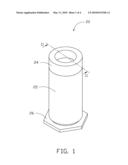
[0008]FIG. 1 is a perspective view of one embodiment of an adjustable fastener.
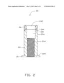
[0009]FIG. 2 is a cross-sectional view of the adjustable fastener taken along line II-II of FIG. 1.
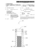
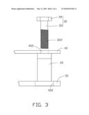
[0010]FIG. 3 is a front plane view of the adjustable fastener of FIG. 1 to be engaged with a mating fastener and used to connect two panels.
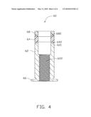
[0011]FIG. 4 is a cross-sectional view of another embodiment of an adjustable fastener.
DETAILED DESCRIPTION
[0012]Referring to FIG. 1, one embodiment of an adjustable fastener 20 includes a main body 22, an elastic portion 24, and a flange 26. The elastic portion 24 and the flange 26 are positioned at opposite ends of the main body 22.
[0013]Referring to FIG. 2, the main body 22 forms an attaching portion 221 at an end adjacent to the elastic portion 24 and defines a neck groove 222 in an end adjacent to the flange 26. The main body 22 may have a rectangular cross section, a square cross section, a triangular cross section, and so on. In the illustrated embodiment, the main body 22 is substantially cylindrical, having a circular cross-section. The main body 22 further defines a threaded engaging hole 224 and a receiving hole 226 communicating with the threaded engaging hole 224. The receiving hole 226 is adjacent to the elastic portion 24. The threaded engaging hole 224 has a diameter smaller than the receiving hole 226. It may be appreciated that the threaded engaging hole 224 may be a through hole extending through the flange 26 or a blind hole.
[0014]The elastic portion 24 has a cross section similar to the cross section of the main body 22. The cross section of the elastic portion 24 may be a rectangular cross section, a square cross section, a triangular cross section, and so on. In the illustrated embodiment, the elastic portion 24 is substantially cylindrical, having a circular cross-section. The elastic portion 24 forms a sleeving portion 244 at an end and defines an extending hole 242 communicating with the receiving hole 226 of the main body 22. The extending hole 242 has a diameter substantially equal to the receiving hole 226. The attaching portion 221 of the main body 22 and the sleeving portion 244 of the elastic portion 24 have an oblique ring-shaped surface, such that the attaching portion 221 firmly engages with the sleeving portion 244. The extending hole 242, the threaded engaging hole 224, and the receiving hole 226 are coaxial. The elastic portion 24 is deformable and may be made of nickel-beryllium-magnesium alloy. Alternatively, the elastic portion 24 may be made of other elastic alloys such as ferrum-manganese alloy, or rubber.
[0015]Referring to FIG. 3, a first panel 40 and a second panel 50 are to be connected by the adjustable fastener 20 and a mating fastener 30. The mating fastener 30 includes a head 34 and a shaft portion 32 including a threaded portion 322 corresponding to the threaded engaging hole 224. The first panel 40 defines a first connecting hole 402, and the second panel 50 defines a second connecting hole 502.
[0016]When connecting the first panel 40 and the second panel 50, the flange 26 of the adjustable fastener 20 is engaged, for example being riveted, in the second connecting hole 502 of the second panel 50. In the process of engaging the adjustable fastener 20 to the second panel 50, displaced material from the second panel 50 around the second connecting hole 502 is displaced into the neck groove 222 of the adjustable fastener 20, thus fixing the adjustable fastener 20 to the second panel 50. The first panel 40 is disposed adjacent to the elastic portion 24 of the adjustable fastener 20, such that the first connecting hole 402 is substantially aligned with the extending hole 242. The shaft portion 32 of the mating fastener 30 extends through the first connecting hole 402, the extending hole 242, and the receiving hole 226, and into the threaded engaging hole 224. The threaded portion 322 of the mating fastener 30 engages with the threaded engaging hole 224. The mating fastener 30 may be turned clockwise or counterclockwise to adjust a length of the elastic portion 24, so that a proper distance and a proper parallelism between the first and second panels 40, 50 may be obtained. Therefore, the distance between the first panel 40 and the second panel 50 can be adjusted to a predetermined value more accurately. Generally, a plurality of adjustable fasteners 20 are adopted to connect the first panel 40 to the second panel 50. Therefore, the parallelism between the first panel 40 and the second panel 50 can be adjusted to a desirable value by adjusting spacing at different locations of the adjustable fastener 20. In addition, the elastic member 24 of the adjustable fastener 20 can absorb shock.
[0017]Referring to FIG. 4, another embodiment of an adjustable fastener 60 is similar to the adjustable fastener 20 except that the adjustable fastener 60 further includes a supporting end 68 besides a main body 62, an elastic portion 64, and a flange 66. The elastic portion 64 and the flange 66 are positioned at opposite ends of the main body 62. The supporting end 68 is formed on an end of the elastic portion 64 opposite to the main body 62. The main body 62 forms an attaching portion 621 at an end adjacent to the elastic portion 64 and defines a neck groove (not labeled) in an end adjacent to the flange 66. The main body 22 further defines a threaded engaging hole 622. The elastic portion 64 forms two sleeving portions 642 at opposite ends. The supporting end 68 forms an attaching portion 682 at an end adjacent to the elastic portion 64. In the illustrated embodiment, the attaching portions 621, 682 are dovetail slots, and the sleeving portions 642 are dovetail protrusions. A length of the elastic portion 64 of the adjustable fastener 60 can also be adjusted by adjusting a mating fastener 30 inwards or outwards from the adjustable fastener 60, such that a proper distance and a proper parallelism between two panels may be obtained. The supporting end 68 is made of a rigid material such as a rigid metal.
[0018]Alternatively, the adjustable fasteners 20, 60 may be adopted to connect more than two components. The adjustable fastener 20 may have other structures, for example, the flange 26, the neck groove 222, and the threads in the threaded engaging hole 224 may be omitted or instead replaced with other structures, so long that the adjustable fastener 20 can connect the first panel 40 with the second panel 50, and the elastic portion 24 is deformable. For example, the main body 22 of the adjustable fastener 20 may form outer threads and the second panel 50 may define a threaded hole for engaging with the outer threads of the adjustable fastener 20, thereby omitting the flange 26. That is, the engagement of the flange 26 and the second connecting hole 502 can be replaced with the engagement of the outer threads of the adjustable fastener 20 and the threaded hole of the second panel 50. Alternatively, the second panel 50 may define a threaded hole, such that the mating fastener 30 runs through the first panel 40 and engages with the threaded hole of the second panel 50, thereby omitting the flange 26 and the threaded engaging hole 224, 622 need not be threaded.
[0019]Finally, while various embodiments have been described and illustrated, the disclosure is not to be construed as being limited thereto. Various modifications can be made to the embodiments by those skilled in the art without departing from the true spirit and scope of the disclosure as defined by the appended claims.
User Contributions:
comments("1"); ?> comment_form("1"); ?>Inventors list |
Agents list |
Assignees list |
List by place |
Classification tree browser |
Top 100 Inventors |
Top 100 Agents |
Top 100 Assignees |
Usenet FAQ Index |
Documents |
Other FAQs |
User Contributions:
Comment about this patent or add new information about this topic:
Images included with this patent application:
 |  |
 |  |
 |
| Similar patent applications: | |
| Date | Title |
|---|---|
| 2013-06-13 | Torque-limited and removable fastener for one-time use |
| 2013-06-13 | Plastic polymer covered fastener |
| 2010-04-22 | Attachment fastener |
| 2010-11-18 | Plate member fastener |
| 2010-11-18 | Plate member fastener |
| New patent applications in this class: | |
| Date | Title |
|---|---|
| 2016-01-14 | Method for manufacturing a nut by the progressive press forging of a laminar metal sheet and resulting nut |
| 2015-10-29 | Multi-piece nut for use with a shock |
| 2015-01-22 | Nut with lug flare |
| 2014-11-13 | Thread repair assembly and thread repair kit |
| 2014-10-30 | Nut and sleeve fastener |
| New patent applications from these inventors: | |
| Date | Title |
|---|---|
| 2012-12-27 | Electronic device with power switch |
| 2012-12-13 | Electronic device with power button assembly |
| 2012-12-06 | Electrical connector with power plug and power socket |
| 2012-06-21 | Protective cover for electronic device |
| 2012-05-31 | Electronic device with clip card installation assembly |
| Top Inventors for class "Expanded, threaded, driven, headed, tool-deformed, or locked-threaded fastener" | |
| Rank | Inventor's name |
|---|---|
| 1 | Jiri Babej |
| 2 | Luke Haylock |
| 3 | Jacob Olsen |
| 4 | Richard Humpert |
| 5 | Paul Gaudron |