Patent application title: CONTROL DEVICE
Inventors:
Jiun-Nan Lu (Tu-Cheng, TW)
Chih-Hsiang Tsai (Tu-Cheng, TW)
Sheng-Han Yang (Tu-Cheng, TW)
Assignees:
HON HAI PRECISION INDUSTRY CO., LTD.
IPC8 Class: AH03K1794FI
USPC Class:
341 20
Class name: Coded data generation or conversion bodily actuated code generator
Publication date: 2010-05-06
Patent application number: 20100109916
a sensor, an analysis unit, and a control unit.
The sensor includes a stationary member and a rotatable member. The
stationary member includes a first electrode and at least two second
electrodes. The rotatable member includes a third electrode and a fourth
electrode. The first electrode electrically contacts the third electrode
and each second electrode electrically contacts the fourth electrode in
sequence when the stationary member is rotated. The analysis unit is
configured for determining which second electrode electrically contacts
the fourth electrode. The control unit is configured for executing a
corresponding command based upon the determination of the analysis unit.Claims:
1. A control device comprising:a sensor comprising a stationary member and
a rotatable member, the stationary member comprising a first electrode
and at least two second electrodes, the rotatable member comprising a
third electrode and a fourth electrode, the first electrode electrically
contacting the third electrode and each second electrode electrically
contacting the fourth electrode in sequence when the stationary member is
rotated;an analysis unit configured for determining which second
electrode electrically contacts the fourth electrode;a control unit
configured for executing a corresponding command based upon the
determination of the analysis unit.
2. The control device of claim 1, wherein the stationary member further comprises a first main body, on which the first and second electrodes are formed.
3. The control device of claim 1, wherein the rotatable member further comprises a second main body comprising a first surface and an opposite second surface, the third and fourth electrodes spiraling from an end of the second main body toward the other end of the second main body.
4. The control device of claim 3, wherein the second main body is substantially fan-shaped.
5. The control device of claim 3, wherein the sensor further comprises a shaft configured for connecting an object, of which rotation is to be detected, to the second main body of the rotatable member.
6. The control device of claim 5, wherein the second main body of the rotatable member defines a rotating center and a through hole aligned therewith, into which the shaft is fitted.
7. The control device of claim 6, wherein the distal end of the third electrode is bent from the first surface to the second surface to form a first contact portion, the distance between the first contact portion and the rotating center of the second main body being substantially equal to the median radius of the first electrode.
8. The control device of claim 6, wherein the distal end of the third electrode is bent from the first surface to the second surface to form a second contact portion, the distance between the second contact portion and the rotating enter of the second main body being substantially equal to the median radius of the annulus where the second electrodes are located.
9. The control device of claim 1, wherein the first electrode is an annular conductive sheet.
10. The control device of claim 9, wherein the at least two second electrodes comprises three second electrodes being conductive sheets, and three discontinuous sectors of an annulus which is concentric about the first electrode.
11. The control device of claim 10, wherein the radians of the three second electrodes are substantially 0-0.44 radians, 0.52-3.93 radians, and 4.01-5.84 radians respectively.
12. The control device of claim 10, wherein the external diameter of the first electrode is less than the inner diameter of the annulus where the three second electrodes are located.
13. The control device of claim 10, wherein the external diameter of the annulus where the three second electrodes are located is less than the inner diameter of the first electrode.Description:
BACKGROUND
[0001]1. Technical Field
[0002]The present disclosure relates to control devices and, particularly, to a control device used in an electrical device.
[0003]2. Description of Related Art
[0004]Hall sensors are frequently used to detect rotation in camera control. However, the detection precision of Hall sensors may not adequately meet the specific device requirements. In addition, to avoid interference between the Hall sensor and the camera with electromagnetic fields, complicated arrangements are required, such that cost and device size are substantially and undesirably increased.
[0005]Therefore, what is called for is a control device applicable in a digital camera which can overcome the described limitations.
BRIEF DESCRIPTION OF THE DRAWINGS
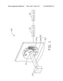
[0006]FIG. 1 is a schematic view of a first embodiment of a control device including a stationary member and a rotatable member.
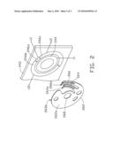
[0007]FIG. 2 is a schematic view of the stationary member and the rotatable member of the control device of FIG. 1.
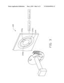
[0008]FIG. 3 is a schematic view of a second embodiment of a control device.
DETAILED DESCRIPTION
[0009]Referring to FIGS. 1-2, a first embodiment of a control device 100 includes a sensor 20, an analysis unit 40, and a control unit 60.
[0010]The sensor 20 includes a shaft 22, a stationary member 24, and a rotatable member 26. The shaft 22 is configured for connecting an object 110, rotation of which is to be detected, to the rotatable member 26. Accordingly, the rotatable member 26 can be rotated by the object 110 via the shaft 22 about a rotating center 01 thereof.
[0011]Here, the control device 100 is used in a digital camera (not shown), wherein the object 110 is a rotatable lens of the digital camera, and the stationary member 24 is a circuit board of the digital camera. It is to be noted, however, that the disclosure is not limited thereto.
[0012]The stationary member 24 includes a first main body 242, a first electrode 244 and three second electrodes 246a, 246b, 246c. The first electrode 244 and the second electrodes 246a, 246b and 246c are disposed on the first main body 242. Here, the first electrode 244 is an annular conductive sheet formed on the first main body 242. The three second electrodes 246a, 246b, 246c are also conductive sheets formed on the first main body 242 as three discontinuous sectors of an annulus, concentric about the first electrode 244. The external diameter of the first electrode 244 is less than the inner diameter of the annulus wherein the second electrodes 246a, 246b and 246c are located.
[0013]The first electrode 244 is pulled down to a low voltage, such as, here, ground. Each of the second electrodes 246a, 246b and 246c are pulled up to corresponding high voltages. Here, the control device 100 further includes an internal power source U1, and can be connected to an external power source U2. The internal power source U1 is configured for pulling the second electrode 246a up to a first high voltage. The external power source U2 is configured for pulling the second electrodes 246b and 246c to a second high voltage. The external power source U2 can be the main power source of the digital camera. Thus, the internal power source U1 can operate before the digital camera is powered on. The external power source U2 can operate after the digital camera has been powered on.
[0014]The radians of the second electrodes 246a, 246b, 246c can be determined by manufacturers. Here, the radian of the second electrode 246a is substantially 0-0.44 radians, the radian of the second electrode 246b is substantially 0.52-3.93 radians, and the radian of the second electrode 246c is substantially 4.01-5.84 radians.
[0015]It should be mentioned that although three second electrodes 246a, 246b, 246c are disclosed, more second electrodes or fewer may be optionally adopted in the disclosed device while remaining well within the scope thereof. Further, the arrangement/layout of the second electrodes is not limited to that disclosed here.
[0016]The rotatable member 26 includes a second main body 262, a third electrode 264, and a fourth electrode 266. The rotating center 01 is defined on the second main body 262. Here, the second main body 262 is substantially fan-shaped. The second main body 262 includes a first surface 262a and an opposite second surface 262b. The third and fourth electrodes 264, 266 spiral from an end of the second main body 262 toward the other end of the second main body 262. The distal ends of the third and fourth electrodes 264 and 266 are bent from the first surface 262a to the second surface 262b to form two contact portions 264a, 266a. The distance between the contact portion 264a and the rotating center 01 is substantially equal to the median radius of the first electrode 244. The distance between the second contact portion 266a and the rotating center 01 of the second main body 262 is substantially equal to the median radius of the annulus where the second electrodes 246a, 246b and 246c are located. In addition, the third and fourth electrodes 264 and 266 are made of a material having elasticity, such as metal. As a result, when the rotatable member 26 is aligned with and disposed on the stationary member 24 and rotated around the rotating center 01, the third electrode 264 keeps contact with the first electrode 244, and the fourth electrode 266 contacts each of the three second electrodes 246a, 246b, 246c in sequence.
[0017]Here, the second main body 262 defines a through hole 268 aligned with the rotating center 01, into which the shaft 22 tightly fits. When the object 110 is rotated, the shaft 22 transmits the rotation to the rotatable member 26.
[0018]The analysis unit 40 is configured for determining which of the second electrodes 246a, 246b, 246c electrically contacts the fourth electrode 266. In detail, as mentioned, when the second electrodes 246a, 246b and 246c do not contact the fourth electrode 266, they are all pulled up to corresponding high voltages. Once one of the second electrodes 246a, 246b and 246c contacts the fourth electrode 266, the voltage thereof will go to low voltage, such as to ground. Accordingly, the analysis unit 40 can determine which second electrode contacts the fourth electrode 266 by detecting the voltage of the three second electrodes. For example, if the second electrode 246a is detected at low voltage, the analysis unit 40 determines that the second electrode 246a contacts the fourth electrode 266. The angle of the object 110 is substantially 0-0.44 radians.
[0019]The control unit 60 is configured for executing a corresponding command based upon the determination of the analysis unit 40. Associations between camera commands and corresponding angle ranges of the object 110 (the connections of the fourth electrode 266 and corresponding second electrodes) are stored in the control unit 60. Here, powering on corresponds to the second electrode 246a contacting the fourth electrode 266, display of a positive orientation picture corresponds the second electrode 246b contacting the fourth electrode 266, and display of a reverse orientation picture corresponds to the second electrode 246c contacting the fourth electrode 266.
[0020]When the fourth electrode 266 contacts the second electrode 246a, the rotated angle of the object 110 is substantially of 0-0.44 radians, and the digital camera is not been powered on. When the fourth electrode 266 contacts the electrode 246b, the rotated angle of the object 110 is substantially 0.52-3.93 radians, the control unit 60 powers the digital camera on, and allows a positive orientation picture to be displayed. When the fourth electrode 266 contacts with the second electrode 246c, the rotated angle of the object 110 is substantially 4.01-5.84 radians, the control unit 60 directs the digital camera to display a reverse orientation picture.
[0021]FIG. 3 shows a second embodiment of a control device 200 differing from the control device 100 of the first embodiment only in that the external diameter of the second electrodes 246a, 246b and 246c is less than the inner diameter of the first electrode 244.
[0022]The control device can execute different commands based upon which second electrode electrically contacts the fourth electrode, allowing the control device to not only conserve space and cost, but also provide accurate detection.
[0023]It is to be understood, however, that even though numerous characteristics and advantages of the embodiments have been set forth in the foregoing description, together with details of the structures and functions of the embodiments, the disclosure is illustrative only, and changes may be made in detail, especially in matters of arrangement of parts within the principles of the invention to the full extent indicated by the broad general meaning of the terms in which the appended claims are expressed.
Claims:
1. A control device comprising:a sensor comprising a stationary member and
a rotatable member, the stationary member comprising a first electrode
and at least two second electrodes, the rotatable member comprising a
third electrode and a fourth electrode, the first electrode electrically
contacting the third electrode and each second electrode electrically
contacting the fourth electrode in sequence when the stationary member is
rotated;an analysis unit configured for determining which second
electrode electrically contacts the fourth electrode;a control unit
configured for executing a corresponding command based upon the
determination of the analysis unit.
2. The control device of claim 1, wherein the stationary member further comprises a first main body, on which the first and second electrodes are formed.
3. The control device of claim 1, wherein the rotatable member further comprises a second main body comprising a first surface and an opposite second surface, the third and fourth electrodes spiraling from an end of the second main body toward the other end of the second main body.
4. The control device of claim 3, wherein the second main body is substantially fan-shaped.
5. The control device of claim 3, wherein the sensor further comprises a shaft configured for connecting an object, of which rotation is to be detected, to the second main body of the rotatable member.
6. The control device of claim 5, wherein the second main body of the rotatable member defines a rotating center and a through hole aligned therewith, into which the shaft is fitted.
7. The control device of claim 6, wherein the distal end of the third electrode is bent from the first surface to the second surface to form a first contact portion, the distance between the first contact portion and the rotating center of the second main body being substantially equal to the median radius of the first electrode.
8. The control device of claim 6, wherein the distal end of the third electrode is bent from the first surface to the second surface to form a second contact portion, the distance between the second contact portion and the rotating enter of the second main body being substantially equal to the median radius of the annulus where the second electrodes are located.
9. The control device of claim 1, wherein the first electrode is an annular conductive sheet.
10. The control device of claim 9, wherein the at least two second electrodes comprises three second electrodes being conductive sheets, and three discontinuous sectors of an annulus which is concentric about the first electrode.
11. The control device of claim 10, wherein the radians of the three second electrodes are substantially 0-0.44 radians, 0.52-3.93 radians, and 4.01-5.84 radians respectively.
12. The control device of claim 10, wherein the external diameter of the first electrode is less than the inner diameter of the annulus where the three second electrodes are located.
13. The control device of claim 10, wherein the external diameter of the annulus where the three second electrodes are located is less than the inner diameter of the first electrode.
Description:
BACKGROUND
[0001]1. Technical Field
[0002]The present disclosure relates to control devices and, particularly, to a control device used in an electrical device.
[0003]2. Description of Related Art
[0004]Hall sensors are frequently used to detect rotation in camera control. However, the detection precision of Hall sensors may not adequately meet the specific device requirements. In addition, to avoid interference between the Hall sensor and the camera with electromagnetic fields, complicated arrangements are required, such that cost and device size are substantially and undesirably increased.
[0005]Therefore, what is called for is a control device applicable in a digital camera which can overcome the described limitations.
BRIEF DESCRIPTION OF THE DRAWINGS
[0006]FIG. 1 is a schematic view of a first embodiment of a control device including a stationary member and a rotatable member.
[0007]FIG. 2 is a schematic view of the stationary member and the rotatable member of the control device of FIG. 1.
[0008]FIG. 3 is a schematic view of a second embodiment of a control device.
DETAILED DESCRIPTION
[0009]Referring to FIGS. 1-2, a first embodiment of a control device 100 includes a sensor 20, an analysis unit 40, and a control unit 60.
[0010]The sensor 20 includes a shaft 22, a stationary member 24, and a rotatable member 26. The shaft 22 is configured for connecting an object 110, rotation of which is to be detected, to the rotatable member 26. Accordingly, the rotatable member 26 can be rotated by the object 110 via the shaft 22 about a rotating center 01 thereof.
[0011]Here, the control device 100 is used in a digital camera (not shown), wherein the object 110 is a rotatable lens of the digital camera, and the stationary member 24 is a circuit board of the digital camera. It is to be noted, however, that the disclosure is not limited thereto.
[0012]The stationary member 24 includes a first main body 242, a first electrode 244 and three second electrodes 246a, 246b, 246c. The first electrode 244 and the second electrodes 246a, 246b and 246c are disposed on the first main body 242. Here, the first electrode 244 is an annular conductive sheet formed on the first main body 242. The three second electrodes 246a, 246b, 246c are also conductive sheets formed on the first main body 242 as three discontinuous sectors of an annulus, concentric about the first electrode 244. The external diameter of the first electrode 244 is less than the inner diameter of the annulus wherein the second electrodes 246a, 246b and 246c are located.
[0013]The first electrode 244 is pulled down to a low voltage, such as, here, ground. Each of the second electrodes 246a, 246b and 246c are pulled up to corresponding high voltages. Here, the control device 100 further includes an internal power source U1, and can be connected to an external power source U2. The internal power source U1 is configured for pulling the second electrode 246a up to a first high voltage. The external power source U2 is configured for pulling the second electrodes 246b and 246c to a second high voltage. The external power source U2 can be the main power source of the digital camera. Thus, the internal power source U1 can operate before the digital camera is powered on. The external power source U2 can operate after the digital camera has been powered on.
[0014]The radians of the second electrodes 246a, 246b, 246c can be determined by manufacturers. Here, the radian of the second electrode 246a is substantially 0-0.44 radians, the radian of the second electrode 246b is substantially 0.52-3.93 radians, and the radian of the second electrode 246c is substantially 4.01-5.84 radians.
[0015]It should be mentioned that although three second electrodes 246a, 246b, 246c are disclosed, more second electrodes or fewer may be optionally adopted in the disclosed device while remaining well within the scope thereof. Further, the arrangement/layout of the second electrodes is not limited to that disclosed here.
[0016]The rotatable member 26 includes a second main body 262, a third electrode 264, and a fourth electrode 266. The rotating center 01 is defined on the second main body 262. Here, the second main body 262 is substantially fan-shaped. The second main body 262 includes a first surface 262a and an opposite second surface 262b. The third and fourth electrodes 264, 266 spiral from an end of the second main body 262 toward the other end of the second main body 262. The distal ends of the third and fourth electrodes 264 and 266 are bent from the first surface 262a to the second surface 262b to form two contact portions 264a, 266a. The distance between the contact portion 264a and the rotating center 01 is substantially equal to the median radius of the first electrode 244. The distance between the second contact portion 266a and the rotating center 01 of the second main body 262 is substantially equal to the median radius of the annulus where the second electrodes 246a, 246b and 246c are located. In addition, the third and fourth electrodes 264 and 266 are made of a material having elasticity, such as metal. As a result, when the rotatable member 26 is aligned with and disposed on the stationary member 24 and rotated around the rotating center 01, the third electrode 264 keeps contact with the first electrode 244, and the fourth electrode 266 contacts each of the three second electrodes 246a, 246b, 246c in sequence.
[0017]Here, the second main body 262 defines a through hole 268 aligned with the rotating center 01, into which the shaft 22 tightly fits. When the object 110 is rotated, the shaft 22 transmits the rotation to the rotatable member 26.
[0018]The analysis unit 40 is configured for determining which of the second electrodes 246a, 246b, 246c electrically contacts the fourth electrode 266. In detail, as mentioned, when the second electrodes 246a, 246b and 246c do not contact the fourth electrode 266, they are all pulled up to corresponding high voltages. Once one of the second electrodes 246a, 246b and 246c contacts the fourth electrode 266, the voltage thereof will go to low voltage, such as to ground. Accordingly, the analysis unit 40 can determine which second electrode contacts the fourth electrode 266 by detecting the voltage of the three second electrodes. For example, if the second electrode 246a is detected at low voltage, the analysis unit 40 determines that the second electrode 246a contacts the fourth electrode 266. The angle of the object 110 is substantially 0-0.44 radians.
[0019]The control unit 60 is configured for executing a corresponding command based upon the determination of the analysis unit 40. Associations between camera commands and corresponding angle ranges of the object 110 (the connections of the fourth electrode 266 and corresponding second electrodes) are stored in the control unit 60. Here, powering on corresponds to the second electrode 246a contacting the fourth electrode 266, display of a positive orientation picture corresponds the second electrode 246b contacting the fourth electrode 266, and display of a reverse orientation picture corresponds to the second electrode 246c contacting the fourth electrode 266.
[0020]When the fourth electrode 266 contacts the second electrode 246a, the rotated angle of the object 110 is substantially of 0-0.44 radians, and the digital camera is not been powered on. When the fourth electrode 266 contacts the electrode 246b, the rotated angle of the object 110 is substantially 0.52-3.93 radians, the control unit 60 powers the digital camera on, and allows a positive orientation picture to be displayed. When the fourth electrode 266 contacts with the second electrode 246c, the rotated angle of the object 110 is substantially 4.01-5.84 radians, the control unit 60 directs the digital camera to display a reverse orientation picture.
[0021]FIG. 3 shows a second embodiment of a control device 200 differing from the control device 100 of the first embodiment only in that the external diameter of the second electrodes 246a, 246b and 246c is less than the inner diameter of the first electrode 244.
[0022]The control device can execute different commands based upon which second electrode electrically contacts the fourth electrode, allowing the control device to not only conserve space and cost, but also provide accurate detection.
[0023]It is to be understood, however, that even though numerous characteristics and advantages of the embodiments have been set forth in the foregoing description, together with details of the structures and functions of the embodiments, the disclosure is illustrative only, and changes may be made in detail, especially in matters of arrangement of parts within the principles of the invention to the full extent indicated by the broad general meaning of the terms in which the appended claims are expressed.
User Contributions:
Comment about this patent or add new information about this topic:
Images included with this patent application:
 |  |
 |  |
| Similar patent applications: | |
| Date | Title |
|---|---|
| 2008-11-27 | Universal remote control device |
| 2008-12-25 | Battery-free remote control device |
| 2009-01-22 | Method and system for controlling a proxy device over a network by a remote device |
| 2009-01-29 | Customizable remote control device |
| 2009-03-12 | A/d converter comprising a voltage comparator device |
| New patent applications in this class: | |
| Date | Title |
|---|---|
| 2014-08-28 | Configurable buttons for electronic devices |
| 2014-04-24 | Touch-sensitive linear adjustment switch |
| 2013-10-24 | Capacitance to code converter with sigma-delta modulator |
| 2013-06-27 | Illuminated keyboard |
| 2013-06-13 | Magnetic force in a directional input device |
| New patent applications from these inventors: | |
| Date | Title |
|---|---|
| 2009-11-12 | Quality monitoring system and method for expirable objects |
| 2009-09-17 | Protective helmet |
| 2009-05-14 | Printed circuit board assembly with shock absorbing structure |
| Top Inventors for class "Coded data generation or conversion" | |
| Rank | Inventor's name |
|---|---|
| 1 | Shiro Dosho |
| 2 | Jong Kee Kwon |
| 3 | Kazuo Matsukawa |
| 4 | Young Deuk Jeon |
| 5 | Ahmed Mohamed Abdelatty Ali |