Patent application title: SEMICONDUCTOR PROCESSING HEAT EXCHANGER SYSTEM
Inventors:
Scott Dickey (Dublin, CA, US)
IPC8 Class: AF24F11053FI
USPC Class:
165247
Class name: Having heating and cooling capability means to control fan or pump to regulate supply air flow or supply water flow responsive to temperature
Publication date: 2010-03-04
Patent application number: 20100051253
Inventors list |
Agents list |
Assignees list |
List by place |
Classification tree browser |
Top 100 Inventors |
Top 100 Agents |
Top 100 Assignees |
Usenet FAQ Index |
Documents |
Other FAQs |
Patent application title: SEMICONDUCTOR PROCESSING HEAT EXCHANGER SYSTEM
Inventors:
Scott Dickey
Agents:
KAUTH , POMEROY , PECK & BAILEY ,LLP
Assignees:
Origin: IRVINE, CA US
IPC8 Class: AF24F11053FI
USPC Class:
165247
Patent application number: 20100051253
Abstract:
A semiconductor fabrication heat exchanger system is provided including
two heat exchangers spaced from each other. The first heat exchanger
receives a high temperature fluid heated from a semiconductor processing
tool or the like and the second heat exchanger has a second fluid with a
set temperature significantly lower than the heated fluid of the first
heat exchanger. A variable and controllable fan removes heat from the
heated fluid and the second heat exchanger cools the heated air.Claims:
1. A semiconductor processing heat exchanger system comprising:a first
heat exchanger having a first fluid;a second heat exchanger spaced from
the first heat exchanger in a non-contacting relationship with the first
heat exchanger, the second heat exchanger having a second fluid, the
second fluid having a set temperature significantly lower than the first
fluid; anda fan arranged to transmit air across the first heat exchanger
to remove heat from the first fluid and a temperature difference between
air transmitted by the fan and first fluid is equal to or greater than
about 100 degrees Celsius.
2. The system of claim 1 wherein the first fluid has a temperature of about 170 to 190 degrees Celsius prior to entering the first heat exchanger and the second fluid has a temperature of about 15 to 25 degrees Celsius prior to entering the second heat exchanger.
3. The system of claim 1 wherein the first heat exchanger has an inlet and an outlet and the first fluid entering the inlet has a temperature higher than the first fluid exiting out the outlet of the first heat exchanger.
4. The system of claim 1 further comprising a sensor monitoring the temperature of the first fluid.
5. The system of claim 4 wherein the fan changes speed based on the monitored first fluid temperature.
6. The system of claim 4 further comprising a controller coupled to the sensor and commanding the fan to change fan speed based on an output from the sensor.
7. The system of claim 4 further comprising a controller coupled to the sensor and configured to increase the fan speed when the first fluid temperature is at or above a specific set temperature and to decrease the fan speed when the first fluid temperature is at or below a specific set temperature.
8. The system of claim 1 wherein the first liquid is a semiconductor processing fluid and the second liquid is water.
9. The system of claim 8 wherein the semiconductor processing fluid consists of GALDEN or FLUORINERT fluid.
10. The system of claim 11 further comprising a semiconductor processing tool coupled to the first heat exchanger and in fluid communication with the semiconductor processing fluid.
11. The system of claim 1 further comprising a semiconductor processing tool transferring heat to the first fluid and the second heat exchanger removing heat from the air transmitted by the fan.
12. The system of claim 1 further comprising an insulated housing enclosing the first and second heat exchangers.
13. The system of claim 1 further comprising a duct in which the fan, the first heat exchanger and the second heat exchanger are enclosed.
14. The system of claim 1 further comprising a reservoir coupled to the first heat exchanger and a pump circulating the first liquid from the reservoir to the first heat exchanger.
15. A semiconductor processing heat exchanger system comprising:a semiconductor processing tool;a first heat exchanger having a first fluid being circulated into and out of the first heat exchanger and to and from the semiconductor processing tool;a second heat exchanger spaced from the first heat exchanger in a non-contacting relationship with the first heat exchanger and separately contained from that of the first heat exchanger, the second heat exchanger having a second fluid, the second fluid having a set temperature significantly lower than the first fluid; anda variable speed fan aligned with the first and second heat exchangers and arranged to transmit air across the first and second heat exchangers, a temperature of the air prior to transmission across the first heat exchanger being significantly lower than a temperature of the first fluid and the temperature of the air after transmission across the first heat exchanger being significantly higher than a temperature of the second fluid.
16. The system of claim 15 further comprising a controller configured to turn on and off the fan and to adjust fan speed of the fan based on the temperature of the first fluid.
17. The system of claim 16 wherein a temperature difference between air transmitted by the fan and first fluid is about 120 to 160 degrees Celsius.
18. The system of claim 17 further comprising:a reservoir coupled to the first heat exchanger;a pump coupled to the reservoir arranged to circulate the first fluid from the reservoir to the semiconductor processing tool; anda sensor coupled to the first heat exchanger and the controller and measuring temperature of the first fluid exiting the first heat exchanger.
19. A method of exchanging heat for a semiconductor fabrication system, the method comprising:heating a first fluid by a semiconductor processing tool;receiving the heated first liquid by a first heat exchanger;transmitting air across the first heat exchanger by a fan, the transmitted air having a temperature significantly higher than the heated first fluid;receiving water by the second heat exchanger, the water having a temperature significantly lower than the heated first fluid;spacing the first heat exchanger from the second heat exchanger; andtransmitting air across the second heat exchanger by the fan.
20. The method of claim 19 further comprising adjusting speed of the fan based on the first fluid's temperature exiting the first heat exchanger.
Description:
CROSS REFERENCE TO RELATED APPLICATIONS
[0001]The application claims the benefit of U.S. Provisional Patent Application No. 61/093,533, filed Sep. 2, 2008, the entire disclosure of which is hereby incorporated by reference as if set forth in full herein.
BACKGROUND
[0002]The present invention generally relates to heat exchanger systems and in particular to semiconductor fabrication liquid to air heat exchanger systems.
[0003]Many industrial applications, such as semiconductor fabrication, utilize a re-circulating fluid specifically provided to cool components or processing tools used in the manufacturing process. Examples of such liquids are liquids manufactured under the trademarks of GALDEN and FLUORINERT. In operation, these liquids reach temperatures substantially above 100° C.
[0004]Typically, the high temperature fluid is cooled through the use of a fluid to fluid heat exchanger in conjunction with the facility's cooling water system to allow subsequent re-use of the fluid in the manufacturing process. However, such a heat exchanger system presents difficulties. For example, depending on the temperature and flow rate of the cooling water, the water can boil causing scale buildup and vibration. Vibration can eventually lead to structural breakdowns, such as cracks in the plates or pipes, and scale buildup reduces the flow rate and overall heat transfer efficiency of the system. Structural breakdowns can further lead to leaks between the two fluids and causing nearly instant vaporization of the cooling water developing into a potentially unsafe high pressure system. One example of such heat exchanger difficulties are described in a paper entitled "Fracture Mechanics For A Plate Heat Exchanger Gasket" by Jonas Lindvall and Marcus Minkkinen, the disclosure of which is hereby incorporated by reference as if set forth in full herein. Constant cooling water flow through the system reduces concerns such as boiling, but such operation can be undesirable and does not eliminate scale/deposit build-up and blockage. Liquid to liquid contact could also lead to explosive results.
[0005]Therefore, there is a need to overcome the above-noted limitations, such as preventing structural damages and the deposit of scales in order to maximize heat transfer efficiency and to provide optimal heat exchange performance.
SUMMARY
[0006]Generally, a semiconductor fabrication heat exchanger system is provided to cool a high temperature fluid used in the fabrication process. In one embodiment, the system includes a first heat exchanger having a first liquid, the high temperature fluid, with a second heat exchanger spaced from the first heat exchanger. The second heat exchanger has a second fluid with a set temperature significantly lower than the first fluid. A variable and controllable fan blows across the first heat exchanger removing heat from the first fluid. The second heat exchanger cools the heated air which is expelled or re-circulated within the system.
[0007]In one embodiment, a semiconductor processing heat exchanger system comprises a first heat exchanger having a first fluid and a second heat exchanger spaced from the first heat exchanger in a non-contacting relationship with the first heat exchanger. The second heat exchanger has a second fluid having a set temperature significantly lower than the first fluid. The system further comprises a fan arranged to transmit air across the first heat exchanger to remove heat from the first fluid and a temperature difference between air transmitted by the fan and first fluid is equal to or greater than about 100 degrees Celsius.
[0008]In another embodiment, a semiconductor processing heat exchanger system comprises a semiconductor processing tool, a first heat exchanger having a first fluid being circulated into and out of the first heat exchanger and to and from the semiconductor processing tool and a second heat exchanger spaced from the first heat exchanger in a non-contacting relationship with the first heat exchanger and separately contained from that of the first heat exchanger. The second heat exchanger has a second fluid having a set temperature significantly lower than the first fluid. The system further comprises a variable speed fan aligned with the first and second heat exchangers and arranged to transmit air across the first and second heat exchangers. The temperature of the air prior to transmission across the first heat exchanger being significantly lower than a temperature of the first fluid and the temperature of the air after transmission across the first heat exchanger being significantly higher than a temperature of the second fluid.
[0009]In yet another embodiment, a method of exchanging heat for a semiconductor fabrication system comprises heating a first fluid by a semiconductor processing tool; receiving the heated first liquid by a first heat exchanger; transmitting air across the first heat exchanger by a fan, the transmitted air having a temperature significantly higher than the heated first fluid; receiving water by the second heat exchanger, the water having a temperature significantly lower than the heated first fluid; spacing the first heat exchanger from the second heat exchanger; and transmitting air across the second heat exchanger by the fan.
[0010]Many of the attendant features of the present invention will be more readily appreciated as the same becomes better understood by reference to the foregoing and following description and considered in connection with the accompanying drawings.
BRIEF DESCRIPTION OF THE DRAWINGS
[0011]FIGS. 1A-1B are block diagrams of a heat exchanger system in accordance with various embodiments of the present invention.
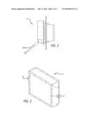
[0012]FIG. 2 illustrates a side view of a variable speed fan in accordance with various embodiments of the present invention.
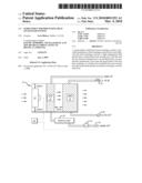
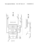
[0013]FIG. 3 illustrates a prospective view of a heat exchanger configured to receive a high temperature fluid in accordance with various embodiments of the present invention.
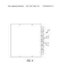
[0014]FIG. 4 illustrates a side view of a heat exchanger configured to receive facility water in accordance with various embodiments of the present invention.
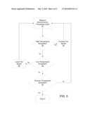
[0015]FIG. 5 is a flow diagram a control process for the heat exchanger system in accordance with various embodiments of the present invention.
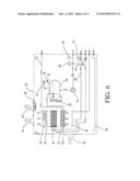
[0016]FIG. 6 is a block diagram of a heat exchanger system in accordance with various embodiments of the present invention.
DETAILED DESCRIPTION
[0017]A heat exchanger system is provided that includes a liquid to air heat exchanger that efficiently cools a high temperature heat transfer liquid. The heat exchanger system causes air to flow across a heat exchanger element containing the high temperature heat transfer liquid. As the air passes over the heat exchanger, the liquid is cooled. The liquid of the first heat exchanger is cooled to a specific temperature and through pumps, valves, and/or pipes is recycled as coolant for cooling objects such as semiconductor-fabrication tools. With heat now transferred to the air, the air becomes heated to an extremely high temperature in excess of 200° C. The heated air flows across a second heat exchanger containing water, thereby transferring heat to the water. The air exhausted from the system is thus cooled and may be re-circulated within the heat exchanger system enclosure.
[0018]In FIG. 1, one embodiment of the system is provided. The system includes a fan 11, a first heat exchanger 21 and a second heat exchanger 31. A servo sensor/controller 41 is coupled to the fan to monitor and regulate the fan speed of the fan 11. The controller monitors the heat transfer liquid's temperature detected by a temperature sensor 19 and applies a PID algorithm to regulate the speed of the fan 11.
[0019]The first heat exchanger is spaced from the fan with sufficient distance to ensure even, uniform flow. For example, the fan may be about 150 mm from the first heat exchanger. Air ducts, vents or other types of air flow components may be placed between the fan and the first heat exchanger to ensure direct and maximum air flow to the first heat exchanger 21. In one embodiment, the fan and first and second heat exchangers are aligned with each other and within or surrounded by a duct or housing 10.
[0020]The first heat exchanger is supplied the high temperature semiconductor processing or first liquid, e.g., GALDEN liquid, through pumps, pipes, valves and other types of fluid flow components. The liquid in one application has a temperature that ranges from about 120-200° C. In one embodiment, the liquid flows in a spiral fashion within one or more spiral formed pipes. As the air from the fan 11 passes over the pipes, fins or plates of the first heat exchanger, heat from the liquid transfers to the air. In one embodiment, the heat transfer rate is about 20 kw. As a result, the air reaches a temperature of about 200° C. The cooled liquid, having a temperature of about 190° C, exits the first heat exchanger. The cooled liquid may be placed in a reservoir 23 to be later used again by the semiconductor manufacturing system which collects it and supplies it to the pump 15. In one embodiment, the pump is a magnetic drive stainless steel pump. The reservoir also has the effect of stabilizing the liquid temperature, as well as providing additional volume should the end user wants to store all the heat transfer fluid inside the heat exchanger system. Additional fluid flow components may be used to assist in the transfer to and from the reservoir.
[0021]As such, when the liquid is delivered or returned back to the first heat exchanger, the liquid is at a temperature higher than a set temperature point. In this case, the set temperature point is about 170-190° C., but it could be anywhere from about 150-200° C. For example, if the liquid is supplied from the first heat exchanger at 170° C., the set temperature point, and then encounters a 20 kw heat load inside the process equipment, the liquid returns back to the first heat exchanger at a temperature of about 179.5° C. (assuming 15 GPM flow). Thus, the liquid entering the first heat exchanger from the object to be cooled or cooling object is hotter than the set temperature point. The fan is used to provide variable cooling inside the first heat exchanger to ensure that the liquid leaves the first heat exchanger at the set temperature point.
[0022]In one embodiment, the first heat exchanger and/or reservoir is coupled to temperature sensors which are connected to the controller that monitors the temperature detected by the temperature sensor. The temperature sensors measure the temperature exiting the first heat exchanger 21. Based on the measured temperature, the controller adjusts the fan speed of the fan 11. In one embodiment, a temperature sensor 22 coupled to the first heat exchanger 21 is arranged to detect the liquid's temperature that is cooled by the first heat exchanger 21. Detected temperatures by temperature sensor are transmitted to the controller 41 that adjusts the speed of fan 11 based on the detected temperatures. For example, if the temperature of the liquid exceeds a specific temperature, (e.g., 170° C.) controller 41 sets the speed of fan higher such that the first heat exchanger 21 can accelerate the rate of heat exchange. If the temperature goes below a specific temperature, fan 11 is set to a slower speed. As such, the temperature of the liquid of the first heat exchanger can be constantly monitored and adjusted by the controller through the fan 11.
[0023]A second heat exchanger 31 is placed about 100 mm from the second heat exchanger. A cooling or second liquid, such as water from the manufacturing facility, is supplied to the second heat exchanger. Water is a desired liquid for the second heat exchanger as it is readily available, cost effective and does not require special handling. The cooling liquid is at a temperature of about 15-25° C. Similar to the first heat exchanger, fluid flow components can be provided to ensure liquid is supplied to the second heat exchanger and air flow components can be provided to ensure air passes properly across the second heat exchanger. In one embodiment, the liquid flows in a spiral fashion within one or more spiral formed pipes. As the heated air passes the second heat exchanger, heat is transferred to the liquid in the second heat exchanger 31 heating the liquid. Due to the small specific heat of air, the temperature of the liquid of the second heat exchanger is prevented from sufficiently heating to reach its boiling point. Since the liquid doesn't reach a boiling point, the liquid will not vibrate the heat exchanger, cause pipe cracking which leads to the instant evaporation of the liquid and a potential explosion, or cause the deposit of scales which lowers heat transfer efficiency. The cooled air exits the system and can be safely vented out without concern with temperature and thereby not requiring particular air flow systems or components to accommodate high temperature air discharge. The air that exchanged heat with the second liquid in one embodiment is cooled to a desired temperature and is then recycled. The heat transfer rate from the air to liquid is about 20 kw. The temperature of the now heated liquid is about 40° C. and the air temperature is about 30° C.
[0024]The heated water is then returned to the facility where it is cooled and recycled back to the different parts of the fab. The system as such effectively transfers heat from the heat transfer fluid, to the facility cooling water, and out of the fab. The heated air optionally could be vented out of the heat exchanger system bypassing or eliminating the use of the second heat exchanger. Such venting, however, can increase the burden on the system or facility to provide specific ducts, baffles, and other air flow components, such as insulated ducts, to properly and safely vent the superheated air.
[0025]Referring again to FIG. 1B, a processing tool 25 introduces a heat load of about 20 kW as described above. The heat load is typically associated with electric heaters and/or microwave heaters utilized to keep a semiconductor substrate at a desired temperature for the semiconductor process such as vapor deposition. The applied temperature tends to slowly increase during the process. Without the above-described heat exchanger system, the increase remains unchecked and thus may damage the processing tool resulting in a stoppage of semiconductor processing. Such a stoppage can be extremely costly to overall manufacturing and sale of the semiconductor device.
[0026]The heat load can also vary. For example, the heat load can vary from 0 to 20 kW during different stages or steps of the semiconductor process. For instance, when the processing tool is idle, e.g., being cleaned or awaiting another substrate, the tool may cool down providing a zero or near zero heat load. A typical liquid-to-liquid heat exchanger has a minimum cooling capacity and thus will continue to cool the tool even if the heat load is zero. The cooling liquid is constantly pumped and thus circulated to reduce deposit build up in the pipes, tubes, etc. within the heat exchanger and to prevent unsafe liquid pressures that may occur. This constant use of a pump or similar types of equipment to ensure constant flow expends electricity and continues to wear on the system components. As such, the energy and wear on the system is wasted to cool down a load that does not need to be cooled. Additionally, the cooling liquid, e.g., water, is monitored for scale deposits or unexpected pressure increases.
[0027]Furthermore, as the semiconductor process continues, the heat on the semiconductor processing tool ramps up to prepare the semiconductor substrate for processing. Additional heat is provided for example by the microwave and electrical heaters to place the substrate at the optimal processing temperature. This effort is hampered by traditional heat exchangers, e.g., liquid-to-liquid heat exchangers, as they will continue to cool the processing tool. As a result, the heaters must expend and thus waste more unnecessary energy to heat the substrate to counteract the heat exchanger. Also, in order to counteract the minimum cooling capacity of traditional heat exchangers, additional processing time is lost to place the substrate at optimal temperature and thus the overall semiconductor processing time suffers. As described throughout this description, the variable fan and the liquid-to-air heat exchanger does not suffer from these limitations. For example, as the fan 11 may be shut off or nearly shut off to provide zero cooling of the heated liquid flowing through the first heat exchanger 21. Likewise, the second heat exchanger may also be shut off or nearly shut off.
[0028]In FIGS. 2-4, examples of the fan 11', first heat exchanger 21' and second heat exchanger 31' are provided. Each component is housed within an insulated enclosure with inlets and outlets for the heat exchangers. The fan 11' is rated to generate about 8 cubic meters/minute air flow. The fan is a variable speed blower capable of being controlled by a controller to increase or decrease speed as desired. The air can also be cooled prior to being introduced into the fan or exiting the fan. In the illustrated embodiment, the fan 11' is a electronically commutated variable speed fan capable of 0 to 100% speed control. An example of the controller is a closed loop, PID control. Examples of the sensors are 100 Ω Pt RTD.
[0029]The first heat exchanger 21' is rated to withstand temperatures of 250° C. Also, the first heat exchanger is capable of transferring heat at a rate of 20 kw. One skilled in the art would appreciate that the system could be scaled differently to handle much lower or much higher heat transfer rates using the same overall system. However, it is a misconception that such a heat exchanger size would be unwieldy which has lead to those in the art to utilize liquid-to-liquid heat exchangers due to their compactness and inherent efficient heat transfer properties. The difference in temperatures between the air and the heated liquid, e.g., a temperature delta of 120 to 160° C., allows the first heat exchanger to be less efficient and also have a smaller form factor. For example, if the temperature delta was less than 90° C. such a heat exchanger may not be efficient enough to reduce the heated liquid to the desired set temperature. In the illustrated embodiment, the first heat exchanger is an Al 3003 alloy welded constructed exchanger having GALDEN liquid flowing into an inlet 26 of the exchanger via a tube and the cooled GALDEN liquid exiting via an outlet 27 through a tube to a reservoir tank 23.
[0030]The second heat exchanger 31' is rated to withstand temperatures of 90° C. Also, the second heat exchanger is capable of transferring heat at a rate of 20 kw. One skilled in the art would appreciate that the heat exchangers may be shell and tube, plate, and other similar types of heat exchangers that provide a liquid to air heat transfer. In the illustrated embodiment, the second heat exchanger is a Cu tube and Al fin constructed exchanger having water supplied into an inlet 32 of the heat exchanger via 3/4'' stainless tubes with a maximum pressure of 2.0 MPa and a safety valve 34. The heated water exits an outlet 33 of the second heat exchanger and through a stainless tube and a check valve 36.
[0031]FIG. 5 is a control flow diagram of the operation of the heat exchanger system. In step 51, the temperature of the semiconductor processing liquid is measured. If the temperature exceeds a high temperature threshold (step 52), fan speed is increased (step 53). Otherwise, if the temperature falls below a low temperature threshold (step 54), fan speed is reduced (step 55). In this manner, power consumption by the fan as well as wear on the fan can be reduced and the heat transfer liquid is maintained at the desired temperature (called the set temperature). In one embodiment, if the temperature exceeds an extreme high temperature threshold (step 57), a fault condition is initiated. Such a fault condition can indicate that the system is not operating properly, such that liquid is not being sufficiently cooled. As such, a fault action may be initiated, for example, one or more valves may be actuated to prevent flow of liquid into and/or out of the first heat exchanger until the fault condition is cleared. Additional sensors or controls can also be utilized to monitor the operation of the fan, heat exchangers and other components utilized in the system to increase performance, identify potential faults early, or as fail-safe processes.
[0032]The temperature controller provides a proportional output to the variable speed blower in order to modulate the cooling capacity. The air exiting the heat exchanger is very hot and difficult to discharge at that temperature, so it is then directed through a heat exchanger cooled by facility cooling water. The result is near room temperature air that can be directed away from the temperature control unit or re-circulated inside the unit itself. By separating the heat transfer fluid and the facility cooling water with an air gap, and using variable airflow to modulate temperature increased performance, safety, and life expectancy of the heat exchanger system is achieved.
[0033]Referring now to FIG. 6, a first heat exchanger 12, the second heat exchanger 16, fan 14, reservoir 24, pump 25 and other parts are arranged in enclosure 32 such that the air cooled by the second heat exchanger can circulate within enclosure 32. In one embodiment, the first and second heat exchangers and the fan are arranged in a duct 18. High temperature fluid 12a flows through the first heat exchanger. In one embodiment, an air intake 33 is arranged in enclosure 32. Air vents 34 and 35 can ventilate air in the enclosure 32. A fan 36 is arranged on air vent 35 in one embodiment. Air intake 33 is also arranged to take outside air into enclosure 32 and by arranging air vents 34 and 35 to let the partial air out from enclosure 32. As such, the air temperature can be controlled and stabilized so that accurate heat transfer can be achieved. Also, in FIG. 6, safety valves 37 and 38 keep the pressure of reservoir 24 constant. Liquid level sensors 39 and 22 detect the level of the first liquid in reservoir 24. These sensors in one embodiment activate an alarm when the level of the liquid is lower than a specified level. Pressure gauges 40 and 42, valve 27, check valve 28, pipes 23 and 26 and drain tanks 43 and 44 are also included to assist in the flow of liquid through the system.
[0034]A semiconductor fabrication heat exchanger system is provided. Although the present invention has been described in certain specific aspects, many additional modifications and variations would be apparent to those skilled in the art. It is therefore to be understood that the present invention may be practiced otherwise than specifically described, including various changes in the size, shape and materials, without departing from the scope and spirit of the present invention. Thus, embodiments of the present invention should be considered in all respects as illustrative and not restrictive.
User Contributions:
comments("1"); ?> comment_form("1"); ?>Inventors list |
Agents list |
Assignees list |
List by place |
Classification tree browser |
Top 100 Inventors |
Top 100 Agents |
Top 100 Assignees |
Usenet FAQ Index |
Documents |
Other FAQs |
User Contributions:
Comment about this patent or add new information about this topic:
Images included with this patent application:
 |  |
 |  |
 |  |
| Similar patent applications: | |
| Date | Title |
|---|---|
| 2011-05-05 | System for cleaning heat exchangers |
| 2011-11-17 | Condensing heat exchanger for gas furnaces |
| 2012-11-22 | Multi-pathway air transfer, thermal energy exchange system |
| 2009-05-07 | Modular heat exchange system |
| 2009-12-24 | Microgravity condensing heat exchanger |
| New patent applications in this class: | |
| Date | Title |
|---|---|
| 2017-08-17 | Heat exchanger ventilator |
| 2016-12-29 | Air conditioning apparatus |
| 2016-06-09 | Water driving pump and temperature control system involving regulation of temperature differential |
| 2016-04-28 | Server rack-dedicated vertical vortex airflow server cooling |
| 2016-03-03 | Temperature distribution prediction method and air conditioning management system |
| Top Inventors for class "Heat exchange" | |
| Rank | Inventor's name |
|---|---|
| 1 | Levi A. Campbell |
| 2 | Chun-Chi Chen |
| 3 | Tai-Her Yang |
| 4 | Robert E. Simons |
| 5 | Richard C. Chu |