Patent application title: Reinforced thermal module structure
Inventors:
Chih-Peng Chen (Sinjhuang City, TW)
Assignees:
ASIA VITAL COMPONENTS CO., LTD.
IPC8 Class: AF28D1500FI
USPC Class:
16510411
Class name: Heat exchange intermediate fluent heat exchange material receiving and discharging heat
Publication date: 2010-02-18
Patent application number: 20100038059
Inventors list |
Agents list |
Assignees list |
List by place |
Classification tree browser |
Top 100 Inventors |
Top 100 Agents |
Top 100 Assignees |
Usenet FAQ Index |
Documents |
Other FAQs |
Patent application title: Reinforced thermal module structure
Inventors:
Chih Peng Chen
Agents:
NIKOLAI & MERSEREAU, P.A.
Assignees:
Asia Vital Components Co., Ltd.
Origin: MINNEAPOLIS, MN US
IPC8 Class: AF28D1500FI
USPC Class:
16510411
Patent application number: 20100038059
Abstract:
A reinforced thermal module structure includes a heat pipe, a radiating
base, and a radiating fin assembly. The heat pipe includes a conducting
section and a heat-dissipating section. The conducting section is in
contact with and connected to the radiating base, and the
heat-dissipating section is extended through and connected to the
radiating fin assembly. The radiating base has at least two support arms.
Each of the support arms has an extended free end extended toward and
pressed against one side of the radiating fin assembly. The support arms
not only help in giving the entire thermal module an enhanced structural
strength, but also in increasing the heat conducting area and heat
dissipating efficiency of the thermal module.Claims:
1. A reinforced thermal module structure, comprising a radiating fin
assembly, a heat pipe, and a radiating base;the heat pipe including a
conducting section and a heat-dissipating section, the heat-dissipating
section being extended through and connected to the radiating fin
assembly, and the conducting section being in contact with and connected
to the radiating base; andthe radiating base having at least two support
arms, and each of the support arms having an extended free end extended
toward and pressed against the radiating fin assembly.
2. The reinforced thermal module structure as claimed in claim 1, wherein the support arms are formed on one face of the radiating base facing toward the radiating fin assembly.
3. The reinforced thermal module structure as claimed in claim 1, further comprising a heat sink disposed on the radiating base.
4. The reinforced thermal module structure as claimed in claim 1, wherein the radiating fin assembly has a bottom facing toward the radiating base, and the extended free ends of the support arms are extended toward and pressed against the bottom of the radiating fin assembly.
5. The reinforced thermal module structure as claimed in claim 2, wherein the radiating fin assembly has a bottom facing toward the radiating base, and the extended free ends of the support arms are extended toward and pressed against the bottom of the radiating fin assembly.
6. The reinforced thermal module structure as claimed in claim 3, wherein the radiating fin assembly has a bottom facing toward the radiating base, and the extended free ends of the support arms are extended toward and pressed against the bottom of the radiating fin assembly.
Description:
FIELD OF THE INVENTION
[0001]The present invention relates to a thermal module structure, and more particularly to a reinforced thermal module structure with enhanced structural strength and increased heat conducting area.
BACKGROUND OF THE INVENTION
[0002]In recent years, with the quick development in electronic information technologies, various kinds of electronic products, such as computers, notebook computers, etc., have become highly popular and been widely applied by users in various fields. Taking computer as an example, with the tendency of increased processing speed and expanded access capacity, a central processing unit (CPU) of the computer working at high speed would also have a constantly increased heating power to generate a large amount of heat during the operation thereof.
[0003]In order to avoid a temporary or permanent failure of the computer due to an overheated CPU thereof, the computer must have sufficient heat-dissipating ability to keep the CPU working normally. Conventionally, for the purpose of removing the heat generated by the CPU during the high-speed operation thereof and keeping the CPU to work normally at the high speed, a thermal module is directly mounted to the CPU, so that the heat generated by the CPU can be quickly dissipated into ambient environment via the thermal module.
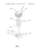
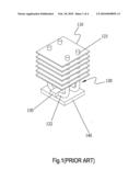
[0004]FIG. 1 shows a conventional thermal module including a radiating fin assembly 110, a heat pipe 120, a fixing section 130, and a radiating base 140. The heat pipe 120 includes a conducting section 122 and a heat-dissipating section 123. The radiating fin assembly 110 is fitted on the heat-dissipating section 123 of the heat pipe 120. The conducting section 122 is held to an interface between the radiating base 140 and the fixing section 130. A bottom face of the radiating base 140 is attached to one surface of a CPU (not shown).
[0005]When the CPU generates heat, the generated heat is transferred via the radiating base 140 to the conducting section 122 of the heat pipe 120, and then transferred from the conducting section 122 to the heat-dissipating section 123, which further transfers the heat to the radiating fin assembly 110, so that the heat is radiated from the radiating fin assembly 110 and diffused into ambient air. However, since the heat pipe 120 is the only element in the thermal module for conducting heat, the large amount of heat generated by the CPU just could not be timely transferred to the radiating fin assembly 110. Moreover, the conducting section 122 is usually partially connected to the fixing section 130 and the radiating base 140 by locally applied solder paste or spot welding, and therefore tends to loosen from the conventional thermal module due to shaking or vibrating during transportation of the thermal module.
[0006]Accordingly, the conventional thermal module has some disadvantages as follows: (1) insufficient structural strength; (2) low heat conducting efficiency; and (3) poor heat dissipating effect.
SUMMARY OF THE INVENTION
[0007]A primary object of the present invention is to provide a reinforced thermal module structure with enhanced structural strength.
[0008]Another object of the present invention is to provide a reinforced thermal module structure with enhanced heat conducting efficiency.
[0009]To achieve the above and other objects, the reinforced thermal module structure according to the present invention includes a radiating fin assembly, a heat pipe, and a radiating base. The heat pipe includes a conducting section and a heat-dissipating section. The heat-dissipating section is extended through and connected to the radiating fin assembly, and the conducting section is in contact with and connected to the radiating base. The radiating base is provided with at least two support arms, each of which has an extended free end in contact with the radiating fin assembly. With the extended free ends in contact with the radiating fin assembly, the support arms not only help in enhancing the structural strength of the thermal module structure, but also in increasing the heat conducting area and accordingly, the heat dissipating effect of the thermal module structure.
BRIEF DESCRIPTION OF THE DRAWINGS
[0010]The structure and the technical means adopted by the present invention to achieve the above and other objects can be best understood by referring to the following detailed description of the preferred embodiments and the accompanying drawings, wherein:
[0011]FIG. 1 is a perspective view of a conventional thermal module;
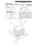
[0012]FIG. 2 is an exploded perspective view of a reinforced thermal module structure according to a first embodiment of the present invention;
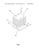
[0013]FIG. 3 is an assembled view of FIG. 2; and
[0014]FIG. 4 is an assembled perspective view of a reinforced thermal module structure according to a second embodiment of the present invention.
DETAILED DESCRIPTION OF THE PREFERRED EMBODIMENTS
[0015]Please refer to FIGS. 2 and 3. A reinforced thermal module structure according to a first embodiment of the present invention includes a radiating fin assembly 20, a heat pipe 30, and a radiating base 40. The radiating fin assembly 20 consists of a plurality of stacked radiating fins 201. The radiating fins 201 each have at least one through hole 202 formed thereon for the heat pipe 30 to extend therethrough, so that the radiating fins 201 are sequentially connected together via the heat pipe 30.
[0016]The heat pipe 30 includes a conducting section 301 and a heat-dissipating section 302. The heat-dissipating section 302 is extended through and connected to the through holes 202 on the radiating fins 201. The conducting section 301 is in contact with the radiating base 40. The radiating base 40 is provided on one side facing toward the radiating fin assembly 20 with at least two support arms 410 and two recesses 420. The conducting section 301 of the heat pipe 30 is received in the recess 420.
[0017]The support arms 410 each have an extended free end 411 being pressed against the radiating fin assembly 20. In other words, the extended free ends 411 of the support arms 410 are extended toward and pressed against a bottom of the radiating fin assembly 20 to thereby give the thermal module structure of the present invention an increased structural strength. In addition, the support arms 410 also function to transfer heat to the radiating fin assembly 20 and thereby enhance the heat conducting efficiency of the radiating base 40.
[0018]Another face of the radiating base 40 facing away from the radiating fin assembly 20 is attached to a heat-generating element (not shown), which can be, for example, a CPU of a computer.
[0019]When the heat-generating element generates heat, the generated heat is conducted by the radiating base 40 to the conducting section 301 of the heat pipe 30, and by the extended free ends 411 of the support arms 410 to the radiating fin assembly 20. The heat is then transferred from the conducting section 301 of the heat pipe 30 to the heat-dissipating section 302, which further transfers the heat to the radiating fin assembly 20. Since the extended free ends 411 of the support arms 410 not only conduct part of the generated heat to the radiating fin assembly 20, but also more securely connect the radiating base 40 with the radiating fin assembly 20, the thermal module structure according to the present invention can have effectively upgraded heat conducting efficiency and structural strength.
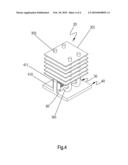
[0020]FIG. 4 shows an enhanced thermal module structure according to a second embodiment of the present invention. In the second embodiment, a heat sink 50 is further provided on one face of the radiating base 40 facing toward the radiating fin assembly 20; and the conducting section 301 of the heat pipe 30 is extended through an interface between the heat sink 50 and the radiating base 40.
[0021]When the heat-generating unit generates heat, the heat is transferred from the radiating base 40 to the heat sink 50, the conducting section 301, and the extended free ends 411 of the support arms 410. Part of the heat transferred to the conducting section 301 is further transferred to the heat-dissipating section 302 and then to the radiating fin assembly 20 connected to the heat-dissipating section 302. Meanwhile, another part of the heat transferred to the conducting section 301 is transferred to the heat sink 50 and the support arms 410. The heat transferred to the heat sink 50 can be quickly radiated and dissipated into ambient air. In the second embodiment, the support arms 410 not only transfer part of the heat to the radiating fin assembly 20, but also directly radiate some part of the heat. Accordingly, in the process of heat transfer in the thermal module structure of the present invention, the support arms 410 not only help in increasing the heat conducting efficiency and the heat conducting area of the thermal module structure, but also in giving the thermal module structure an enhanced structural strength.
[0022]With the above arrangements, the reinforced thermal module structure of the present invention provides the following advantages: (1) enhanced structural strength; (2) increased heat conducting efficiency; and (3) good heat dissipating effect.
[0023]The present invention has been described with some preferred embodiments thereof and it is understood that many changes and modifications in the described embodiments can be carried out without departing from the scope and the spirit of the invention that is intended to be limited only by the appended claims.
User Contributions:
comments("1"); ?> comment_form("1"); ?>Inventors list |
Agents list |
Assignees list |
List by place |
Classification tree browser |
Top 100 Inventors |
Top 100 Agents |
Top 100 Assignees |
Usenet FAQ Index |
Documents |
Other FAQs |
User Contributions:
Comment about this patent or add new information about this topic:
| People who visited this patent also read: | |
| Patent application number | Title |
|---|---|
| 20100079471 | Display System Having Floating Point Rasterization and Floating Point Framebuffering |
| 20100079469 | Rendering tremmed nurbs on programmable graphics architectures |
| 20100079467 | TIME DEPENDENT VIRTUAL UNIVERSE AVATAR RENDERING |
| 20100079466 | ASYNCHRONOUS STREAMING OF DATA FOR VALIDATION |
| 20100079465 | INTUITIVELY CONNECTING GRAPHICAL SHAPES |
Images included with this patent application:
 |  |
 |  |
 |
| Similar patent applications: | |
| Date | Title |
|---|---|
| 2010-02-18 | Reinforced thermal module structure |
| 2011-01-06 | System and method for creating an open loop with optional closed-loop riparian geothermal infrastructure |
| 2011-01-06 | System and method for creating a closed-loop riparian geothermal infrastructure |
| 2011-02-10 | Thermal module mount structure |
| 2011-12-15 | Wear-resistant conformal coating for micro-channel structure |
| New patent applications in this class: | |
| Date | Title |
|---|---|
| 2015-03-05 | Method for pooling thermal energy, and heat exchange loop system between industrial and tertiary sites |
| 2015-02-26 | Air conditioner |
| 2014-12-04 | Cooling of chill molds using baffles |
| 2014-10-30 | Unified cooling in multiple polyolefin polymerization reactors |
| 2014-10-23 | Heat exchanger, and energy recovery device and energy recovery system comprising heat exchanger |
| New patent applications from these inventors: | |
| Date | Title |
|---|---|
| 2010-04-15 | Liquid-cooling type thermal module |
| 2010-02-11 | Heat sink testing method |
| 2009-12-31 | Radiating fin |
| 2009-11-26 | Light-emitting diode lampshade with heat-radiating effect |
| Top Inventors for class "Heat exchange" | |
| Rank | Inventor's name |
|---|---|
| 1 | Levi A. Campbell |
| 2 | Chun-Chi Chen |
| 3 | Tai-Her Yang |
| 4 | Robert E. Simons |
| 5 | Richard C. Chu |