Patent application title: Method and Device to Detect Failure of Static Pervasive Control Signals
Inventors:
Matthias Klein (Boeblingen, DE)
Matthias Klein (Boeblingen, DE)
Andreas Wagner (Boeblingen, DE)
Gerhard Zilles (Jettingen, DE)
Manfred H. Walz (Boeblingen, DE)
Thomas Buechner (Weil Im Schonbuch, DE)
Assignees:
International Business Machines Corporation
IPC8 Class: AG01R313177FI
USPC Class:
714732
Class name: Pulse or data error handling digital logic testing signature analysis
Publication date: 2010-01-21
Patent application number: 20100017667
monitoring and detecting an error in the static
pervasive signals applied to input/output pins of an integrated circuit
during functional operation of the integrated circuit. The method and
circuits provide a signal signature of each of one or more groups of the
static pervasive signals and then monitoring the signal signature for any
change of logic level.Claims:
1. A method for detecting failures on static pervasive signals applied to
I/O pins of an integrated circuit, said method comprising:grouping the
signals into one or more groups;building a signal signature for each of
the one or more groups;feeding each of the signal signatures of the one
or more groups into a separate store element comprising an input and an
output;comparing each of the signal signatures for the one or more groups
with the output of the store element into which it is fed;creating a
signature mismatch for each of the signal signatures that differs from
the output of the store element into which it is fed; andpresenting each
of the signature mismatches as an error indicator output.Description:
FIELD OF INVENTION
[0001]Monitoring and detecting fails of static signals on I/O pins of a semiconductor circuit
BACKGROUND
[0002]A large number of I/O pins of a computer chip are used to provide signals for the chips maintenance and infrastructure and are not used for functional use or for traffic flow. Most of these signals either specify a static setting or are used in functions which are only needed in the initialization of the chip. During functional operation mode of the chip, all these signals are supposed to remain at a static value. However, sometimes, the development of shorts and opens or other fail mechanisms such as the injection of noise by induction will cause the signal integrity to be compromised despite all prior verification and signal noise analysis.
SUMMARY
[0003]The invention comprises a method and apparatus for monitoring and detecting errors occurring on the input/output (I/O) pins of an integrated circuit.
[0004]An exemplary embodiment of the invention presents a method for detecting failures on static pervasive signals applied to I/O pins of an integrated circuit. The method comprises the grouping of the static pervasive signals into one or more groups, building a signal signature for each of the one or more groups, feeding each of the signal signatures of the one or more groups into a store element and comparing each of the signal signatures for the one or more groups with the output of the store element into which it is fed. If there is an error such that the static pervasive signal is changed, a signature mismatch for each of the signal signatures that differs from the output of the store element into which it is fed is created and presented as an error indicator output.
[0005]An exemplary embodiment of a logical implementation of the present invention is represented for each group of I/O pins as follows. The group of two or more I/O pins has each pin feeding its signal into a separate receiver circuit. The output of each receiver, in turn, is fed into a signal signature circuit. An example of such a signal signature circuit would be an exclusive or (XOR) circuit. The single output of the signal signature circuit is then fed into a storage element. An example of a storage element is a latch circuit. The output of the storage element and the output of the signal signature circuit are fed into a compare circuit. The results at the output of the compare circuit are then fed into capture logic where it is retained as an error or non-error indicator.
BRIEF DESCRIPTION OF DRAWINGS
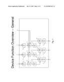
[0006]FIG. 1--Represents an overview of an exemplary embodiment of the invention showing the signal flow of groups of I/O pins with static pervasive signals to be monitored for the development of errors.
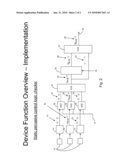
[0007]FIG. 2--Represents an exemplary embodiment of a group of I/O pins with static pervasive signals with a logic block diagram from the I/O to error capture.
DETAILED DESCRIPTION OF INVENTION
[0008]FIG. 1 represents a general overview of an exemplary example of the invention. Here, the static pervasive signals to be monitored, coming in to the input/output pins are grouped into three groups 1, 2, and 3 with two signals in each group. Each group is then fed into a separate signal signature circuit 4. As an option, each group of I/O pins to be monitored would be gated, either before or after having their signal signature generated. In FIG. 1, this gating is illustrated in the gating function blocks 5 and controlled by a gating signal 6. This will allow the signals to be switched during non-functional operations such as built-in-self-test (BIST), personalization changes, etc. with the monitoring and error indication circuit being transparent to these operations.
[0009]The signal signatures are then each fed into a separate storage element 7. Each signal signature coming into the storage element is compared to the signal signature at the output of the storage element by compare circuits 8. If a signal mismatch occurs as a result of the compare, the mismatch is indicated and held by the mismatch circuits 9. The mismatch circuits 9 may then be interrogated at outputs 10, 11, and 12.
[0010]FIG. 2 represents an exemplary embodiment of the implantation of the monitoring and error detection of a group of static pervasive signals applied to I/O pins of an integrated circuit. In this example there are three such signals and corresponding I/O pads 13. The signals from each of the pads are fed into a separate receiver circuit 14. The outputs 15 of two of the three receiver circuits 14 are shown to be non-erroneous pervasive static signals of a logic zero level for two periods of time. The third receiver output 16 erroneously switches from a logic zero to a logic one over the same two periods of time. These three receiver outputs are fed into separate optional gating AND circuits 18 gated by gate signal 17. The two signals 15 and the one erroneous signal 16 are propagated through the gating circuits 18 into the signal signature circuit, in this example an XOR circuit 21. The output of the XOR circuit 21 is then fed into the input of a storage element 24, such as a latch circuit, which is clocked by a domain clock 25. Then the input signal 22 is clocked an additional clock period to produce signal 23 and the output signal 26 of the storage element are compared by compare circuit 27, such as an XOR circuit, to produce error indicator signal 28 which is then fed into a capture circuit through line 29.
[0011]The circuit arrangement and composition may be different from that exemplified above. For example, the gating function may occur after the signal signature function. Also, the I/O identified above may not only be external I/O but may be internal to the chip. The capture circuit fed by line 29 is not shown as this is typically part of the processor chip circuitry.
Claims:
1. A method for detecting failures on static pervasive signals applied to
I/O pins of an integrated circuit, said method comprising:grouping the
signals into one or more groups;building a signal signature for each of
the one or more groups;feeding each of the signal signatures of the one
or more groups into a separate store element comprising an input and an
output;comparing each of the signal signatures for the one or more groups
with the output of the store element into which it is fed;creating a
signature mismatch for each of the signal signatures that differs from
the output of the store element into which it is fed; andpresenting each
of the signature mismatches as an error indicator output.Description:
FIELD OF INVENTION
[0001]Monitoring and detecting fails of static signals on I/O pins of a semiconductor circuit
BACKGROUND
[0002]A large number of I/O pins of a computer chip are used to provide signals for the chips maintenance and infrastructure and are not used for functional use or for traffic flow. Most of these signals either specify a static setting or are used in functions which are only needed in the initialization of the chip. During functional operation mode of the chip, all these signals are supposed to remain at a static value. However, sometimes, the development of shorts and opens or other fail mechanisms such as the injection of noise by induction will cause the signal integrity to be compromised despite all prior verification and signal noise analysis.
SUMMARY
[0003]The invention comprises a method and apparatus for monitoring and detecting errors occurring on the input/output (I/O) pins of an integrated circuit.
[0004]An exemplary embodiment of the invention presents a method for detecting failures on static pervasive signals applied to I/O pins of an integrated circuit. The method comprises the grouping of the static pervasive signals into one or more groups, building a signal signature for each of the one or more groups, feeding each of the signal signatures of the one or more groups into a store element and comparing each of the signal signatures for the one or more groups with the output of the store element into which it is fed. If there is an error such that the static pervasive signal is changed, a signature mismatch for each of the signal signatures that differs from the output of the store element into which it is fed is created and presented as an error indicator output.
[0005]An exemplary embodiment of a logical implementation of the present invention is represented for each group of I/O pins as follows. The group of two or more I/O pins has each pin feeding its signal into a separate receiver circuit. The output of each receiver, in turn, is fed into a signal signature circuit. An example of such a signal signature circuit would be an exclusive or (XOR) circuit. The single output of the signal signature circuit is then fed into a storage element. An example of a storage element is a latch circuit. The output of the storage element and the output of the signal signature circuit are fed into a compare circuit. The results at the output of the compare circuit are then fed into capture logic where it is retained as an error or non-error indicator.
BRIEF DESCRIPTION OF DRAWINGS
[0006]FIG. 1--Represents an overview of an exemplary embodiment of the invention showing the signal flow of groups of I/O pins with static pervasive signals to be monitored for the development of errors.
[0007]FIG. 2--Represents an exemplary embodiment of a group of I/O pins with static pervasive signals with a logic block diagram from the I/O to error capture.
DETAILED DESCRIPTION OF INVENTION
[0008]FIG. 1 represents a general overview of an exemplary example of the invention. Here, the static pervasive signals to be monitored, coming in to the input/output pins are grouped into three groups 1, 2, and 3 with two signals in each group. Each group is then fed into a separate signal signature circuit 4. As an option, each group of I/O pins to be monitored would be gated, either before or after having their signal signature generated. In FIG. 1, this gating is illustrated in the gating function blocks 5 and controlled by a gating signal 6. This will allow the signals to be switched during non-functional operations such as built-in-self-test (BIST), personalization changes, etc. with the monitoring and error indication circuit being transparent to these operations.
[0009]The signal signatures are then each fed into a separate storage element 7. Each signal signature coming into the storage element is compared to the signal signature at the output of the storage element by compare circuits 8. If a signal mismatch occurs as a result of the compare, the mismatch is indicated and held by the mismatch circuits 9. The mismatch circuits 9 may then be interrogated at outputs 10, 11, and 12.
[0010]FIG. 2 represents an exemplary embodiment of the implantation of the monitoring and error detection of a group of static pervasive signals applied to I/O pins of an integrated circuit. In this example there are three such signals and corresponding I/O pads 13. The signals from each of the pads are fed into a separate receiver circuit 14. The outputs 15 of two of the three receiver circuits 14 are shown to be non-erroneous pervasive static signals of a logic zero level for two periods of time. The third receiver output 16 erroneously switches from a logic zero to a logic one over the same two periods of time. These three receiver outputs are fed into separate optional gating AND circuits 18 gated by gate signal 17. The two signals 15 and the one erroneous signal 16 are propagated through the gating circuits 18 into the signal signature circuit, in this example an XOR circuit 21. The output of the XOR circuit 21 is then fed into the input of a storage element 24, such as a latch circuit, which is clocked by a domain clock 25. Then the input signal 22 is clocked an additional clock period to produce signal 23 and the output signal 26 of the storage element are compared by compare circuit 27, such as an XOR circuit, to produce error indicator signal 28 which is then fed into a capture circuit through line 29.
[0011]The circuit arrangement and composition may be different from that exemplified above. For example, the gating function may occur after the signal signature function. Also, the I/O identified above may not only be external I/O but may be internal to the chip. The capture circuit fed by line 29 is not shown as this is typically part of the processor chip circuitry.
User Contributions:
Comment about this patent or add new information about this topic:
Images included with this patent application:
 |  |
| New patent applications in this class: | |
| Date | Title |
|---|---|
| 2016-06-09 | Determining transient error functional masking and propagation probabilities |
| 2016-03-24 | Test device and method |
| 2016-03-17 | Method for speeding up boolean satisfiability |
| 2016-01-28 | Accelerated and accuracy-enhanced delay and noise injection calculation for analysis of a digital circuit using grid computing |
| 2015-04-23 | Implementing misr compression methods for test time reduction |
| New patent applications from these inventors: | |
| Date | Title |
|---|---|
| 2019-10-17 | Normalization of a product on a datapath |
| 2016-05-05 | Dynamic evaluation and adaption of hardware hash functions |
| 2016-05-05 | Increased bandwidth of ordered stores in a non-uniform memory subsystem |
| 2016-05-05 | Increased bandwidth of ordered stores in a non-uniform memory subsystem |
| 2016-04-07 | Initializing i/o devices |
| Top Inventors for class "Error detection/correction and fault detection/recovery" | |
| Rank | Inventor's name |
|---|---|
| 1 | Lee D. Whetsel |
| 2 | Jason K. Resch |
| 3 | Gary W. Grube |
| 4 | Shaohua Yang |
| 5 | Timothy W. Markison |