Patent application title: ELECTRCAL CONNECTOR FOR RECEIVING A CPU
Inventors:
Fang-Jwu Liao (Tu-Cheng, TW)
Assignees:
HON HAI PRECISION INDUSTRY CO., LTD.
IPC8 Class: AH01R1200FI
USPC Class:
439 79
Class name: Preformed panel circuit arrangement, e.g., pcb, icm, dip, chip, wafer, etc. distinct contact secured to panel circuit panel circuit adapted to move along panel plane relative to coupling part for insertion of male contact
Publication date: 2010-01-14
Patent application number: 20100009559
Inventors list |
Agents list |
Assignees list |
List by place |
Classification tree browser |
Top 100 Inventors |
Top 100 Agents |
Top 100 Assignees |
Usenet FAQ Index |
Documents |
Other FAQs |
Patent application title: ELECTRCAL CONNECTOR FOR RECEIVING A CPU
Inventors:
FANG-JWU LIAO
Agents:
WEI TE CHUNG;FOXCONN INTERNATIONAL, INC.
Assignees:
HON HAI PRECISION INDUSTRY CO., LTD.
Origin: SANTA CLARA, CA US
IPC8 Class: AH01R1200FI
USPC Class:
439 79
Patent application number: 20100009559
Abstract:
An electrical connector for receiving a CPU (1) includes a plurality of
terminals (3) and an insulative housing (2). The insulative housing (2)
includes a rectangular mating face (21), and the rectangular mating face
defines a plurality of passageways, said plurality of terminals are
received in the passageway. The mating face is surrounded by four lateral
side walls (22), and the lateral side walls together with the mating face
to form a cavity, the cavity is used to received the CPU (1). wherein the
lateral side wall comprises an inner surface (220) facing the cavity, and
the inner surface defines at least two fixing blocks (221) perpendicular
to each other, and wherein, each fixing block has ribs to engage the CPU.Claims:
1. An electrical connector for receiving a CPU, comprising:a plurality of
terminals;an insulative housing comprising a rectangular mating face and
receiving the terminals; whereinthe mating face is surrounded by four
lateral side walls, and the lateral side walls together with the mating
face forms a cavity;wherein the lateral side wall comprises an inner
surface facing the cavity, and the inner surface defines at least two
fixing blocks oriented perpendicular to each other, and wherein each
fixing block has ribs to engage the CPU.
2. The electrical connector as claimed in claim 1, wherein each fixing block comprises a pair of ribs, the pair of ribs are paralleled to each other, and the rib extends along a direction perpendicular the mating face.
3. The electrical connector as claimed in claim 1, wherein the housing defines at least one cutout between the at least two fixing blocks.
4. An electrical connector comprising:an insulative housing defining a base and a plurality of side walls extending upwardly from a periphery of the base, said base cooperating with said side walls to commonly defining a receiving cavity;at least one immoveable fixing block unitarily formed on an interior surface of each of said side walls, said fixing block defining a main face facing toward the receiving cavity in a transverse direction along which said fixing block extends from the corresponding side wall toward the receiving cavity; andat least one rib unitarily formed on said main face of the fixing block facing toward the receiving cavity for engagement with an electronic package received in the receiving cavity.
5. The electrical connector as claimed in claim 4, wherein said rib is dimensioned smaller than said fixing block in said transverse direction.
6. The electrical connector as claimed in claim 4, where there are two of said rib formed upon said fixing block.
7. The electrical connector as claimed in claim 4, wherein said fixing block is equipped with a beveled top surface for facilitating downward loading of the electronic package into the receiving cavity.
8. The electrical connector as claimed in claim 4, wherein there are plural pairs of said fixing block, each pair being disposed at a corresponding corner of said housing.
9. The electrical connector as claimed in claim 4, further including at least one protrusion portion formed on the interior to be received in a notch of the electronic package.
Description:
BACKGROUND OF THE INVENTION
[0001]1. Field of the Invention
[0002]The present invention relates to an electrical socket connector, and more particularly to an electrical socket connector for receiving a central processing unit (CPU).
[0003]2. Description of Prior Arts
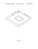
[0004]FIG. 1 shows a conventional electrical socket connector for receiving a CPU, which has a housing and two detachable flexible arms assembled to the housing. After the CPU is assembled to the socket, the arms engage with the CPU, so as to assure the CPU staying in the socket. However, the detachable arms complicate assembling operation, and the cost of the socket will increase.
[0005]Therefore, it is desirable to provide a new electrical socket connector that decreases the cost of the connector.
SUMMARY OF THE INVENTION
[0006]Accordingly, an object of the present invention is to provide an electrical connector with low cost.
[0007]In order to achieve afore-mentioned object, An electrical connector for receiving a CPU includes a plurality of terminals and an insulative housing. The insulative housing includes a rectangular mating face, and the rectangular mating face defines a plurality of passageways, said plurality of terminals are received in the passageway. The mating face is surrounded by four lateral side walls, and the lateral side walls together with the mating face to form a cavity, the cavity is used to received the CPU. wherein the lateral side wall comprises an inner surface facing the cavity, and the inner surface defines at least two fixing blocks perpendicular to each other, and wherein, each fixing block has ribs to engage the CPU.
[0008]Other objects, advantages and novel features of the invention will become more apparent from the following detailed description of the present embodiment when taken in conjunction with the accompanying drawings.
BRIEF DESCRIPTION OF THE DRAWING
[0009]FIG. 1 is a perspective view of a conventional electrical connector;
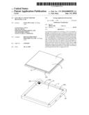
[0010]FIG. 2 is an exploded view of an electrical connector in accordance with the present invention;
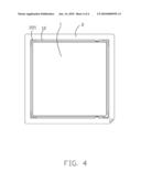
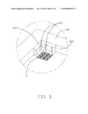
[0011]FIG. 3 is an enlarged view of an encircled portion of the connector in FIG. 2; and
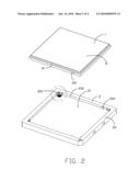
[0012]FIG. 4 is a top plan view of FIG. 2 after the CPU is assembled to the electrical connector.
DETAILED DESCRIPTION OF THE PREFERRED EMBODIMENT
[0013]Referring to FIGS. 2 to 4, an electrical connector according to the present invention includes an insulative housing 2 and a plurality of terminals 3 received in the housing 2. A central processing unit (CPU) 1 is received in the electrical connector.
[0014]The CPU is configurated rectangular, and includes a main portion 11 and lateral sides 12 surrounding the main portion 11. A pair of notches 120 are defined on two opposite lateral sides 12, respectively.
[0015]The insulative housing 2 has a mating face 21 and lateral side wall 22. A plurality of passageways (not labeled) defined on the mating face 21 penetrated the insulative housing 2. And a plurality of terminals 3 are inserted into the passageway, respectively. The FIG. 2 shows only a part of passageways and terminals 3. The mating face 21 accompanied with the lateral side wall 22 to form a cavity (not labeled), the cavity is used to receive the CPU 1. The lateral side walls 22 has inner side surfaces 220 which face the cavity. A pair of protrusion portion 222 are defined on two opposite inner side surface 220 respectively, to match the notches 120 of the CPU. The protrusion portions 222 and the notches 120 work cooperatively to make the CPU 1 assemble to the electrical connector in a correct orientation.
[0016]The insulative housing 2 includes four inner side surfaces 220, and every inner side surface defines a pair of fixing block 221, and there is a cutout (not labeled) between the pair of fixing block 221. The fixing blocks 221 defined on opposite inner side surfaces 220 are arranged in face to face. The fixing block 211 has a pair of ribs 223, the ribs 223 extend along a direction perpendicular to the mating face 21. And the rib 223 has a blade (not labeled) which is toward the cavity, a cross-section of the rib 233 is configurated triangular. The ribs 223 and the insulative housing 2 are modeled integrally.
[0017]Referring to FIG. 4, the CPU is assembled into the cavity of the insulative housing 2, and the ribs 223 of the fixing block engage with the lateral side 12 of the CPU. So that, the CPU is fixed in the electrical connector stability. And the rib 223 and the lateral side 12 touch in a line because of the blade. So that, the CPU is assembled to the insulative housing 2 easily, and stays in the cavity stability. In other embodiments, the fixing block 221 can be defined on one inner side surface 220, two one inner side surfaces 220 or three one inner side surfaces 220.
[0018]It is to be understood, however, that even though numerous characteristics and advantages of the present invention have been set forth in the foregoing description, together with details of the structure and function of the invention, the disclosure is illustrative only, and changes may be made in detail, especially in matters of shape, size, and arrangement of parts within the principles of the invention to the full extent indicated by the broad general meaning of the terms in which the appended claims are expressed.
User Contributions:
comments("1"); ?> comment_form("1"); ?>Inventors list |
Agents list |
Assignees list |
List by place |
Classification tree browser |
Top 100 Inventors |
Top 100 Agents |
Top 100 Assignees |
Usenet FAQ Index |
Documents |
Other FAQs |
User Contributions:
Comment about this patent or add new information about this topic:
| People who visited this patent also read: | |
| Patent application number | Title |
|---|---|
| 20100026079 | TRANSPORTER VEHICLE |
| 20100026078 | Dynamic trunk support system |
| 20100026076 | LAYERED TECHNOLOGY FOR ENERGY MANAGEMENT OF VEHICLE SEATING |
| 20100026074 | HEADREST AND VEHICLE SEAT PROVIDED WITH THE SAME |
| 20100026071 | SEAT RECLINING APPARATUS FOR VEHICLE |
Images included with this patent application:
 |  |
 |  |
 |
| Similar patent applications: | |
| Date | Title |
|---|---|
| 2010-04-29 | Electrical connector for receiving cpu |
| 2011-03-31 | Electrical connector with grooves receiving crumbs |
| 2011-07-07 | Electrical connector for holding a lamp |
| 2009-11-26 | Electrical connector having linear actuator |
| 2009-12-10 | Electrcal connector with detachable aligning key |
| New patent applications in this class: | |
| Date | Title |
|---|---|
| 2016-02-18 | Blind via printed circuit board fabrication supporting press fit connectors |
| 2015-11-05 | Straddle mount connector and pluggable transceiver module having the same |
| 2015-10-22 | Light-emitting universal serial bus socket |
| 2014-09-18 | Connector of a universal serial bus device |
| 2014-07-24 | Electrcial connector and assemble method of the same |
| New patent applications from these inventors: | |
| Date | Title |
|---|---|
| 2012-05-10 | Electrical connector with improved alignment structure |
| 2011-06-23 | Electrical connector having contact terminals with deflective arms facing each in twisted manner |
| 2011-05-26 | High density electrical connector |
| 2011-02-24 | Electrical connector assembly for facilitating heat dissipation |
| 2011-02-10 | Hybrid connector having diffrent contacts for engaging with different types of packages |
| Top Inventors for class "Electrical connectors" | |
| Rank | Inventor's name |
|---|---|
| 1 | Jerry Wu |
| 2 | Noah Montena |
| 3 | Qi-Sheng Zheng |
| 4 | Jun Chen |
| 5 | Norman R. Byrne |