Patent application title: ELECTRICAL CONNECTOR FOR RECEIVING CPU
Inventors:
Fang-Jwu Liao (Tu-Cheng, TW)
Chun-Yi Chang (Tu-Cheng, TW)
Assignees:
HON HAI PRECISION INDUSTRY CO., LTD.
IPC8 Class: AH01R1200FI
USPC Class:
439 64
Class name: Electrical connectors preformed panel circuit arrangement, e.g., pcb, icm, dip, chip, wafer, etc. with guide for directing panel circuit movement
Publication date: 2010-04-29
Patent application number: 20100105218
1) for receiving a CPU (5) includes a rectangular
planar receiving portion (10) having a top surface (14) for mating with
the CPU. At least two posts (20) extend perpendicularly from corners of
the planar receiving portion. At least two posts and the planar receiving
portion together define a receiving space for receiving the CPU. The post
includes a resilient portion (22) and a fixing portion (24). A gap (241)
is defined between a resilient portion and a fixing portion, and the
resilient portion forms a protrusion block (26) protruding into the
receiving space.Claims:
1. An electrical connector for receiving a CPU, comprising:a rectangular
planar receiving portion having a top surface for mating with the CPU;at
least two posts extending perpendicularly from corners of the planar
receiving portion, at least two posts and the planar receiving portion
together defining a receiving space for receiving the CPU, each post
comprising a resilient portion and a fixing portion; wherein a gap is
defined between the resilient portion and the fixing portion, and the
resilient portion forms a protrusion block protruding into the receiving
space.
2. The electrical connector as claimed in claim 1, wherein the resilient portion has a tip end and a main portion, the protrusion block is disposed on a connecting portion between the tip end and the main portion.
3. The electrical connector as claimed in claim 2, wherein the tip end defines a guiding surface for guiding the CPU.
4. The electrical connector as claimed in claim 1, wherein the gap between the resilient portion and the fixing portion is defined.
5. The electrical connector as claimed in claim 4, wherein the fixing portion is able to prevent the resilient portion from flexing excessively when the resilient portion is driven back to the fixing portion.
6. An electrical connector comprising:an insulative housing including a plurality of fixing potions at four corners and commonly defining a center receiving portion thereamong, each of said fixing portions defining a right angle recess facing said center receiving portion;a plurality of resilient portions respectively located in the corresponding recesses and respectively spaced from the corresponding fixing portions, and facing toward said center receiving portion; each of said resilient portions defining a tapered tip end and a protruding block below said tapered tip end.
7. The electrical connector as claimed in claim 6, wherein said resilient portion essentially spans with a ninety-degree range while said protruding block only occupies a portion of said ninety-degree range.
8. The electrical connector as claimed in claim 7, wherein said resilient portion includes a middle vertical section, and upper and lower wedged section by two ends of said vertical section in a vertical direction, and wherein said upper wedged section is linked to the tapered tip end.
9. The electrical connector as claimed in claim 7, wherein said protruding block is located around one of the end position within said ninety-degree range.
10. The electrical connector as claimed in claim 7, wherein said housing defines a through hole under each of the corresponding protruding block for injection molding consideration.Description:
BACKGROUND OF THE INVENTION
[0001]1. Field of the Invention
[0002]The present invention generally relates to an electrical connector, and in particularly to a central processing unit (CPU) socket for receiving a CPU.
[0003]2. Description of Related Patent
[0004]Conventionally, the CPU socket is an electrical device for providing an electrical connecting path between a print circuit board (PCB) and a CPU. The CPU socket includes an insulative housing and a plurality of terminals received in the insulative housing. The insulative housing is rectangular, and a top surface of the insulative housing defines a receiving space for receiving the CPU. The plurality of terminals are received in a bottom wall of the receiving space. The receiving space is rectangular, and is surrounded by four lateral side walls. A flexible arm is formed on an inner surface of two of the four lateral side walls, and the flexible arm extends in two the receiving space to engage with the CPU. The CPU is suffered pressure force from the flexible arm. Therefore, the CPU is fixed in the receiving space.
[0005]Currently, the size of the CPU socket became smaller and smaller. The traditional CPU socket can not fit the miniaturization trend, because the structure of the CPU socket is more complex.
[0006]Therefore, it is desirable to provide a new CPU socket that eliminates the aforesaid problems.
BRIEF SUMMARY OF THE INVENTION
[0007]Accordingly, an object of the present invention is to provide a new CPU socket with simple structure.
[0008]In order to achieve afore-mentioned object, the CPU socket for receiving a CPU comprises a rectangular planar receiving portion having a top surface for mating with the CPU. At least two posts extend perpendicularly from corners of the planar receiving portion, at least two posts and the planar receiving portion together defines a receiving space for receiving the CPU. The post comprises a resilient portion and a fixing portion. A gap is defined between a resilient portion and a fixing portion, and the resilient portion forms a protrusion block protruding into the receiving space.
[0009]Other objects, advantages and novel features of the invention will become more apparent from the following detailed description of the present embodiment when taken in conjunction with the accompanying drawings.
BRIEF DESCRIPTION OF THE DRAWINGS
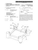
[0010]FIG. 1 is a perspective view of a CPU socket in accordance to the present invention; and
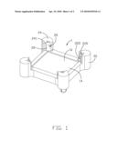
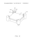
[0011]FIG. 2 is a perspective view of the CPU socket has a CPU.
DETAILED DESCRIPTION OF THE INVENTION
[0012]Reference to FIGS. 1 to 2, the present invention relates to a CPU socket 1 for receiving a CPU 5. The CPU socket 1 includes a planar receiving portion 10 and the planar receiving portion 10 is rectangular. Each corner (not labeled) of the rectangular planar receiving portion 10 has post 20. The four posts 20 and the planar receiving portion 10 form a receiving space (not labeled) for receiving the CPU 5. The planar receiving portion 10 and the four posts 20 are formed integrally. A plurality of terminals (not shown) is received in the planar receiving portion 10 for providing an electrical connecting between the CPU 5 and a PCB (not shown) or other similar electrical devices.
[0013]The post 20 includes a resilient portion 22 and a fixing portion 24 paralleled to the resilient portion 22. The resilient portion 22 and the fixing portion 24 are extended upwardly from a top surface 14 of the planar receiving portion 10 and perpendicular to the top surface 14. The resilient portion 22 is disposed on an inner side of the fixing portion 24. There is a gap 241 defined between the resilient portion 22 and the fixing portion 24. The resilient portion 22 has a tip end 220 and a main portion 222. The tip end 220 defines a guiding surface (not labeled). A protruding block 26 is defined on an inner surface of the resilient portion 22, and the protruding block 26 is disposed on a connecting portion between the tip end 220 and the main portion 222.
[0014]When the CPU 5 is disposed in the receiving space, the CPU 5 engages with the guiding surfaces of the four tip ends 220. And the resilient portion 22 is driven by the CPU 5 to flex to the fixing portion 24. The fixing portion 24 is able to prevent the flexible flexing excessively. After the CPU 5 being completely received in the receiving space, the inner surface of the resilient portion 22 engages with the CPU 5 to fix the CPU 5 in the receiving space. The protruding block 26 restricts the CPU 5 removing from the receiving space.
[0015]The post 20 in the present invention includes a fixing portion 24 and a resilient portion 22. The gap 241 between the fixing portion 24 and the resilient portion 22 make the resilient portion 22 is able to flex to the fixing portion 24. And the fixing portion 24 is able to engage with the resilient portion 22 to prevent the flexible flexing excessively.
[0016]It is to be understood, however, that even though numerous characteristics and advantages of the present invention have been set forth in the foregoing description, together with details of the structure and function of the invention, the disclosure is illustrative only, and changes may be made in detail, especially in matters of shape, size, and arrangement of parts within the principles of the invention to the full extent indicated by the broad general meaning of the terms in which the appended claims are expressed.
Claims:
1. An electrical connector for receiving a CPU, comprising:a rectangular
planar receiving portion having a top surface for mating with the CPU;at
least two posts extending perpendicularly from corners of the planar
receiving portion, at least two posts and the planar receiving portion
together defining a receiving space for receiving the CPU, each post
comprising a resilient portion and a fixing portion; wherein a gap is
defined between the resilient portion and the fixing portion, and the
resilient portion forms a protrusion block protruding into the receiving
space.
2. The electrical connector as claimed in claim 1, wherein the resilient portion has a tip end and a main portion, the protrusion block is disposed on a connecting portion between the tip end and the main portion.
3. The electrical connector as claimed in claim 2, wherein the tip end defines a guiding surface for guiding the CPU.
4. The electrical connector as claimed in claim 1, wherein the gap between the resilient portion and the fixing portion is defined.
5. The electrical connector as claimed in claim 4, wherein the fixing portion is able to prevent the resilient portion from flexing excessively when the resilient portion is driven back to the fixing portion.
6. An electrical connector comprising:an insulative housing including a plurality of fixing potions at four corners and commonly defining a center receiving portion thereamong, each of said fixing portions defining a right angle recess facing said center receiving portion;a plurality of resilient portions respectively located in the corresponding recesses and respectively spaced from the corresponding fixing portions, and facing toward said center receiving portion; each of said resilient portions defining a tapered tip end and a protruding block below said tapered tip end.
7. The electrical connector as claimed in claim 6, wherein said resilient portion essentially spans with a ninety-degree range while said protruding block only occupies a portion of said ninety-degree range.
8. The electrical connector as claimed in claim 7, wherein said resilient portion includes a middle vertical section, and upper and lower wedged section by two ends of said vertical section in a vertical direction, and wherein said upper wedged section is linked to the tapered tip end.
9. The electrical connector as claimed in claim 7, wherein said protruding block is located around one of the end position within said ninety-degree range.
10. The electrical connector as claimed in claim 7, wherein said housing defines a through hole under each of the corresponding protruding block for injection molding consideration.
Description:
BACKGROUND OF THE INVENTION
[0001]1. Field of the Invention
[0002]The present invention generally relates to an electrical connector, and in particularly to a central processing unit (CPU) socket for receiving a CPU.
[0003]2. Description of Related Patent
[0004]Conventionally, the CPU socket is an electrical device for providing an electrical connecting path between a print circuit board (PCB) and a CPU. The CPU socket includes an insulative housing and a plurality of terminals received in the insulative housing. The insulative housing is rectangular, and a top surface of the insulative housing defines a receiving space for receiving the CPU. The plurality of terminals are received in a bottom wall of the receiving space. The receiving space is rectangular, and is surrounded by four lateral side walls. A flexible arm is formed on an inner surface of two of the four lateral side walls, and the flexible arm extends in two the receiving space to engage with the CPU. The CPU is suffered pressure force from the flexible arm. Therefore, the CPU is fixed in the receiving space.
[0005]Currently, the size of the CPU socket became smaller and smaller. The traditional CPU socket can not fit the miniaturization trend, because the structure of the CPU socket is more complex.
[0006]Therefore, it is desirable to provide a new CPU socket that eliminates the aforesaid problems.
BRIEF SUMMARY OF THE INVENTION
[0007]Accordingly, an object of the present invention is to provide a new CPU socket with simple structure.
[0008]In order to achieve afore-mentioned object, the CPU socket for receiving a CPU comprises a rectangular planar receiving portion having a top surface for mating with the CPU. At least two posts extend perpendicularly from corners of the planar receiving portion, at least two posts and the planar receiving portion together defines a receiving space for receiving the CPU. The post comprises a resilient portion and a fixing portion. A gap is defined between a resilient portion and a fixing portion, and the resilient portion forms a protrusion block protruding into the receiving space.
[0009]Other objects, advantages and novel features of the invention will become more apparent from the following detailed description of the present embodiment when taken in conjunction with the accompanying drawings.
BRIEF DESCRIPTION OF THE DRAWINGS
[0010]FIG. 1 is a perspective view of a CPU socket in accordance to the present invention; and
[0011]FIG. 2 is a perspective view of the CPU socket has a CPU.
DETAILED DESCRIPTION OF THE INVENTION
[0012]Reference to FIGS. 1 to 2, the present invention relates to a CPU socket 1 for receiving a CPU 5. The CPU socket 1 includes a planar receiving portion 10 and the planar receiving portion 10 is rectangular. Each corner (not labeled) of the rectangular planar receiving portion 10 has post 20. The four posts 20 and the planar receiving portion 10 form a receiving space (not labeled) for receiving the CPU 5. The planar receiving portion 10 and the four posts 20 are formed integrally. A plurality of terminals (not shown) is received in the planar receiving portion 10 for providing an electrical connecting between the CPU 5 and a PCB (not shown) or other similar electrical devices.
[0013]The post 20 includes a resilient portion 22 and a fixing portion 24 paralleled to the resilient portion 22. The resilient portion 22 and the fixing portion 24 are extended upwardly from a top surface 14 of the planar receiving portion 10 and perpendicular to the top surface 14. The resilient portion 22 is disposed on an inner side of the fixing portion 24. There is a gap 241 defined between the resilient portion 22 and the fixing portion 24. The resilient portion 22 has a tip end 220 and a main portion 222. The tip end 220 defines a guiding surface (not labeled). A protruding block 26 is defined on an inner surface of the resilient portion 22, and the protruding block 26 is disposed on a connecting portion between the tip end 220 and the main portion 222.
[0014]When the CPU 5 is disposed in the receiving space, the CPU 5 engages with the guiding surfaces of the four tip ends 220. And the resilient portion 22 is driven by the CPU 5 to flex to the fixing portion 24. The fixing portion 24 is able to prevent the flexible flexing excessively. After the CPU 5 being completely received in the receiving space, the inner surface of the resilient portion 22 engages with the CPU 5 to fix the CPU 5 in the receiving space. The protruding block 26 restricts the CPU 5 removing from the receiving space.
[0015]The post 20 in the present invention includes a fixing portion 24 and a resilient portion 22. The gap 241 between the fixing portion 24 and the resilient portion 22 make the resilient portion 22 is able to flex to the fixing portion 24. And the fixing portion 24 is able to engage with the resilient portion 22 to prevent the flexible flexing excessively.
[0016]It is to be understood, however, that even though numerous characteristics and advantages of the present invention have been set forth in the foregoing description, together with details of the structure and function of the invention, the disclosure is illustrative only, and changes may be made in detail, especially in matters of shape, size, and arrangement of parts within the principles of the invention to the full extent indicated by the broad general meaning of the terms in which the appended claims are expressed.
User Contributions:
Comment about this patent or add new information about this topic:
| People who visited this patent also read: | |
| Patent application number | Title |
|---|---|
| 20150145070 | MERGING LITHOGRAPHY PROCESSES FOR GATE PATTERNING |
| 20150145069 | SILICON GERMANIUM FINFET FORMATION |
| 20150145068 | STRUCTURE OF FinFETs |
| 20150145067 | FIN STRUCTURE |
| 20150145066 | SEMICONDUCTOR DEVICE AND METHOD OF MAKING |
Images included with this patent application:
 |  |
 |
| Similar patent applications: | |
| Date | Title |
|---|---|
| 2011-03-10 | Apparatus and method for electrical connection clamping |
| 2011-03-17 | Terminal connector for a regulator |
| 2012-08-09 | Electrical connector device |
| 2013-06-06 | Electrical connector terminal |
| 2013-06-20 | Connect/disconnect connector for coaxial cable |
| New patent applications in this class: | |
| Date | Title |
|---|---|
| 2017-08-17 | Electrical connector assembly |
| 2016-03-31 | Cosmetically self-centering removable module tray |
| 2015-12-24 | Programming connector for electrically connecting an external electronic device to circuit board containing a programmable component |
| 2015-12-10 | High speed circuit board to circuit board connector via mating in an orthogonal direction to the axis of the pins |
| 2015-02-26 | Communication connector |
| New patent applications from these inventors: | |
| Date | Title |
|---|---|
| 2012-05-10 | Electrical connector with improved alignment structure |
| 2011-06-23 | Electrical connector having contact terminals with deflective arms facing each in twisted manner |
| 2011-05-26 | High density electrical connector |
| 2011-04-28 | Sink type electrical connector with l-shaped frame |
| Top Inventors for class "Electrical connectors" | |
| Rank | Inventor's name |
|---|---|
| 1 | Jerry Wu |
| 2 | Noah Montena |
| 3 | Qi-Sheng Zheng |
| 4 | Jun Chen |
| 5 | Norman R. Byrne |