Patent application title: CORE PIN UNIT FOR DIE CASTING
Inventors:
Seung San Lee (Busan, KR)
Assignees:
Hyundai Motor Company
IPC8 Class: AB22D4500FI
USPC Class:
164340
Class name: Means to shape metallic material including means to assemble mold parts core positioning means
Publication date: 2009-12-17
Patent application number: 20090308563
Inventors list |
Agents list |
Assignees list |
List by place |
Classification tree browser |
Top 100 Inventors |
Top 100 Agents |
Top 100 Assignees |
Usenet FAQ Index |
Documents |
Other FAQs |
Patent application title: CORE PIN UNIT FOR DIE CASTING
Inventors:
Seung San Lee
Agents:
EDWARDS ANGELL PALMER & DODGE LLP
Assignees:
HYUNDAI MOTOR COMPANY
Origin: BOSTON, MA US
IPC8 Class: AB22D4500FI
USPC Class:
164340
Patent application number: 20090308563
Abstract:
A core pin unit for die casting mounted inside a movable mold including a
core die and a core holder for forming a hole at a mold is provided,
which comprises a core pin body being inserted into both the core holder
and the core die, a locking screw mounted at the rear end of the core pin
body inserted into the core holder, a spring interposed between the core
pin body and the locking screw in the core holder; and a cooler mounted
at the rear end of the core pin body. The core pin unit prevents a core
pin body from bending due to a load of a molten metal introduced and from
being damaged by vibration thereof.Claims:
1. A core pin unit for die casting, which is mounted inside a movable mold
including a core die and a core holder for forming a hole at a mold, the
core pin unit comprising:a core pin body being inserted into both the
core holder and the core die such that a front end of the core pin body
protrudes forwardly from the core die and a rear end thereof protrudes
rearwardly from the core holder, a middle portion thereof including a
circular supporter formed along an exterior circumference thereof;a
locking screw mounted at the rear end of the core pin body inserted into
the core holder;a spring interposed between the core pin body and the
locking screw in the core holder; anda cooler mounted at the rear end of
the core pin body in such a state that it is inserted into the core pin
body so as to cool the core pin body.
2. The core pin unit for die casting of claim 1, wherein the core pin body is provided with a circulation passage formed along a length direction thereof so that the cooler is inserted therein, and a screw thread is formed at the rear end thereof.
3. The core pin unit for die casting of claim 1, wherein the locking screw is provided with a penetrating hole into which the core pin body is inserted, and a screw thread is formed at an exterior circumference thereof so as to be connected to the core holder by screws.
4. The core pin unit for die casting of claim 3, wherein an insert groove is formed at the rear end of the locking screw so that a tool is mounted at the core holder.
5. The core pin unit for die casting of claim 1, wherein the cooler comprises:a mounting connector having a front portion threaded to a rear end of the core pin and an oil passage formed therein;a coolant supply nipple integrally coupled to the rear end of the mounting connector, and communicated with the cooling pump so as to receive a coolant;a coolant supply pipe integrally coupled to the coolant supply nipple, which penetrates the oil passage from the front of the mounting connector, and which is inserted into the core pin body so as to supply the core pin body with the coolant; anda coolant exhaust nipple integrally coupled to the rear end of the mounting connector, and communicated with the oil passage so as to exhaust the coolant that is provided to the inside of the core pin body through the coolant supply pipe and that is subsequently used for cooling.
Description:
CROSS-REFERENCE TO RELATED APPLICATION
[0001]This application claims priority to and the benefit of Korean Patent Application No. 10-2008-0054804 filed on Jun. 11, 2008, the entire contents of which are incorporated herein by reference.
BACKGROUND
[0002](a) Technical Field
[0003]The present invention relates to a core pin unit for die casting, and more particularly to a core pin unit for die casting that is mounting on molds so as to form a hole during casting.
[0004](b) Description of the Related Art
[0005]Generally, die casting involves supplying a molten metal to a mold formed of metal that is machining-processed.
[0006]For such die casting, molds are manufactured to precise measurements so it is not necessary to process a finish, such that they have superior mechanical properties for mass production. Materials for the die casting are, for example, zinc, aluminum, tin, and copper, and the molds are manufactured by a casting device using air pressure, water pressure, and hydraulic pressure.
[0007]Such a mold for die casting is made of a metal and includes an operating holder provided with a mold unit and a fixed holder.
[0008]A core die is provided at the operating holder of the mold unit and a core holder supporting the core die is mounted at a rear of the core die, and the core holder is connected to an operating rod mounted at the base of a cylinder.
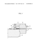
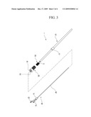
[0009]Herein, a plurality of core pin units 100 are mounted at the core die so as to form holes during production.
[0010]As shown in FIG. 1, the core pin unit 100 includes a core pin body 110 inserted to the core die 101, a locking screw 111 mounted at the core holder 103, a spring 113 interposed between the core pin body 110 and the locking screw 111, and a cooler 115 that penetrates the locking screw 111 and is inserted into the core pin body 110 so as to supply cooling water thereto.
[0011]As the technical structure of the core pin unit 100 is known (e.g., Korean Patent Application No 10-2005-0113236 discloses), a detailed description thereof will be omitted.
[0012]However, since the core pin unit according to the prior art absorbs a load through a spring so as to prevent the core pin from bending because of the molten metal, and at that time, the core pin body is moved back and forth by the spring and shock occurs during assembly of the cooler caused by the forward/rearward movement resulting in a problem of damaging the cooler.
[0013]In addition, when the cooler is damaged by the forward/rearward movement of the core pin body, a resulting product is deteriorated due to the leakage of the coolant, as is productivity.
[0014]The above information disclosed in this Background section is only for enhancement of understanding of the background of the invention and therefore it may contain information that does not form the prior art that is already known in this country to a person of ordinary skill in the art.
SUMMARY OF THE INVENTION
[0015]The present invention has been made in an effort to provide a core pin unit for die casting having advantages of preventing a core pin body that is used to form a hole in a product from bending because of a load of a molten metal at a mold, and preventing the core pin body from being damaged by vibration thereof, and thereby increasing the life cycle of a cooler and improving productivity.
[0016]A core pin unit for die casting according to an exemplary embodiment of the present invention, which is mounted inside a movable mold including a core die and a core holder for forming a hole at a mold, may include:
[0017]a core pin body that penetrates both the core holder and the core die, wherein the front end thereof protrudes forwardly from the front of the core die and the rear end thereof protrudes rearwardly from the rear of the core holder, and that has a circular supporter along an exterior circumference thereof; a locking screw mounted at the rear end of the core pin body inserted into the core holder; a spring interposed between the core pin body and the locking screw in the core holder; and a cooler mounted at the rear end of the core pin body in such a state that it is inserted into the core pin body so as to cool the core pin body.
[0018]The core pin body may be provided with a circulation passage in a length direction thereof so that the cooler is inserted therein, and a screw thread is formed at the rear end thereof.
[0019]The locking screw may be provided with a penetrating hole so that the core pin body is inserted therein, and a screw thread is formed at a forward exterior circumference thereof so as to be connected to the core holder by screws.
[0020]The locking screw may further include an insert groove at the rear end thereof so that a tool is mounted at the core holder.
[0021]The cooler may include: a mounting connector coupled to the rear end of the core pin body by screws, and provided with an oil passage therein; a coolant supply nipple integrally coupled to the rear end of the mounting connector, and communicated with the cooling pump so as to receive a coolant; a coolant supply pipe integrally coupled to the coolant supply nipple through which the oil passage penetrates from the front of the mounting connector, and inserted into the core pin body so as to supply the core pin body with the coolant; and an coolant exhaust nipple integrally coupled to the rear end of the mounting connector, and communicated with the oil passage so as to exhaust the coolant that is provided to the inside of the core pin body through the coolant supply pipe and that is subsequently used for cooling.
[0022]Accordingly, if the core pin unit for die casting according to an exemplary embodiment of the present invention is employed in a die casting process according to an exemplary embodiment of the present invention, the core pin body can be prevented from bending by means of absorbing a load of a molten metal through the spring.
[0023]As can be seen from the foregoing, the life-time of the cooler is extended by damage thereto being prevented, and productivity is improved by minimizing inferior goods caused by a leak of the coolant when the cooler is damaged.
BRIEF DESCRIPTION OF THE DRAWINGS
[0024]FIG. 1 is a schematic diagram showing a core pin unit for die casting according to the prior art.
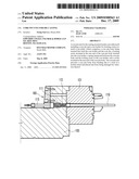
[0025]FIG. 2 is a cross-sectional view of a core pin unit for die casting according to an exemplary embodiment of the present invention.
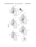
[0026]FIG. 3 is an exploded perspective view showing a core pin unit for die casting according to an exemplary embodiment of the present invention.
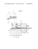
[0027]FIG. 4 shows respective operational steps of a core pin unit for die casting according to an exemplary embodiment of the present invention.
DETAILED DESCRIPTION OF THE EMBODIMENTS
[0028]An exemplary embodiment of the present invention will hereinafter be described in detail with reference to the accompanying drawings.
[0029]FIG. 2 is a cross-sectional view of a core pin unit for die casting according to an exemplary embodiment of the present invention, and FIG. 3 is an exploded perspective view of the core pin unit for die casting according to an exemplary embodiment of the present invention.
[0030]Referring to the drawings, a core pin unit 1 for die casting according to an exemplary embodiment of the present invention is mounted inside a movable mold 7 including a core die 3 and core holder 5 so as to form a hole inside a product.
[0031]The core pin unit 1 for die casting according to an exemplary embodiment of the present invention can prevent a core pin body for forming a hole in a product from being bent by a load of molten metal flowing into a cavity of the mold, and preventing the freely moving core pin body from being damaged by vibration of the core pin body, and can thereby increase the life cycle of a cooler and improve productivity.
[0032]As shown in FIG. 2 and FIG. 3, the core pin unit for die casting according to an exemplary embodiment of the present invention includes a core pin body 10, a locking screw 20, a spring 30, and a cooler 40.
[0033]The core pin body 10 penetrates both the core holder 5 and the core die 3, and a front portion of the core pin body 10 protrudes forwardly and the end portion thereof protrudes rearwardly from the core holder 5.
[0034]Herein, the core pin body 10 is provided with a circulation passage 11 along a length direction thereof so that the cooler 40 can be inserted therein, and has a circular supporter along an exterior circumference thereof.
[0035]In addition, a screw thread is formed at the rear end of the core pin body 10 so that the cooler 40 can be mounted thereon.
[0036]The locking screw 20 is mounted at the rear end of the core holder 5 in a state such that the rear end of the core pin body 10 penetrates the locking screw 20.
[0037]In this case, a penetrating hole 21 is formed inside the locking screw 20 so that the core pin body 10 can be inserted therein.
[0038]Further, in case of mounting the locking screw 20 to the core holder 5, an insert groove 23 is formed so that a tool 50 can be placed therein.
[0039]The locking screw 20 prevents escape of the core pin body 10 from the core die 3 and the core holder 5.
[0040]The spring 30 is interposed between the core pin body 10 and the locking screw 20 in the core holder 5.
[0041]At this time, the spring 30 may be, e.g., a type of coil spring such that one end of the spring 30 is supported by a circular supporter 13 of the core pin body 10, and the other end of the spring 30 is supported by the locking screw 20.
[0042]Such a spring 30 absorbs a load of molten metal so as to prevent the core pin body 10 from bending because of the load of the molten metal.
[0043]As an exemplary embodiment of the present invention, the cooler 40 is inserted into the core pin body 10 from the rear end thereof so as to cool the core pin body 10, and includes a mounting connector 41, a coolant supply nipple 43, a coolant supply pipe 45, and a coolant exhaust nipple 47.
[0044]Firstly, an oil passage 42 is formed in the mounting connector 41, and the front end of the core pin body 10 is connected to the core pin body 10 by screws through a screw thread formed at the rear end of the core pin body 10.
[0045]Further, the coolant supply nipple 43 is integrally coupled to the rear end of the mounting connector 41.
[0046]The coolant supply nipple 43 is connected to a coolant pump (not shown) so as to receive the coolant.
[0047]In addition, the coolant supply pipe 45 that is inserted into the circulation passage 11 is communicated with the coolant supply nipple 43.
[0048]The coolant supply pipe 45 is integrally coupled to the coolant supply nipple 43 in a state such that the coolant supply pipe 45 penetrates the oil passage 42.
[0049]Such a coolant supply pipe 45 cools the core pin body 10 by providing the inside the core pin body 10 with the coolant received from the coolant supply nipple 43 in a casting process.
[0050]The coolant exhaust nipple 47 is integrally coupled to the rear end of the mounting connector 41.
[0051]The coolant exhaust nipple 47 exhausts the coolant used for cooling by communicating with the oil passage 42.
[0052]Hereinafter, assembly/operation processes of the core pin unit 1 according to an exemplary embodiment of the present invention will be described in detail.
[0053]FIG. 4 shows respective operational steps of the core pin unit for die casting according to an exemplary embodiment of the present invention.
[0054]Firstly, as shown in S1 of FIG. 4, the core pin body 10 is inserted into the rear end of the movable mold 7 and the core holder 5 so that the core pin body 10 penetrates the core holder 5 and core die 3.
[0055]In this case, the front end of the core pin body 10 protrudes in a direction at predetermined lengthwise intervals thereof from the rear end of the core holder 5.
[0056]Subsequently, as shown in S2 of FIG. 4, the spring 30 is inserted to the rear end of the core pin body 10.
[0057]The spring 30 is inserted to the core pin body 10 along the exterior circumference thereof, and the other end is supported by the circular supporter 13 of the core pin body 10.
[0058]When the inserting of the spring 30 is completed, as shown in S3 of FIG. 4, after the locking screw 20 is inserted to the core holder 5, as shown in S4 of FIG. 4, the locking screw 20 is fixedly connected to the core holder 5 by means of the tool 50.
[0059]In this case, a catching projection 51 is formed to the front end of the tool 50 corresponding to the insert groove 23 in the locking screw 20.
[0060]In addition, an inserting hole 53 that is provided with the core pin body 10 is formed at the tool 50 so as to prevent interference of the core pin body 10 when mounted the locking screw 20.
[0061]That is to say, after the catching projection 51 is engaged to the insert groove 23 in the locking screw 20, the locking screw 20 is coupled to the core holder 5 by rotating of the locking screw 20 through the tool 50 in a state such that rear end of the core pin body 10 is inserted to the inserting hole 53.
[0062]When the assembling of the locking screw 20 is completed, as shown in S5 of FIG. 4, the coolant supply pipe 45 in the cooler 40 is inserted to the circulation passage 11.
[0063]Then, the assembling of the core pin unit 1 is completed by connecting the mounting connector 41 to the rear end of the core pin body 10.
[0064]In a casting process of the core pin unit 1 for die casting according to an exemplary embodiment of the present invention, the core pin body 10 can be prevented from bending by means of absorbing a load of the molten metal through the spring 30.
[0065]As a result of the foregoing, the impact power of the direct delivery of molten metal to the cooler 40 can be reduced owing to the extension of the rear length thereof, and mounting of the cooler 40 at the rear end thereof minimizes the vibration of the core pin body 10 to the cooler 40 under the load of the molten metal.
[0066]In addition, damage to the cooler 40 is decreased, which results in a long life thereof by minimizing impact power of the core pin body 10 to the cooler 40.
[0067]Accordingly, if the core pin unit for die casting according to an exemplary embodiment of the present invention is employed, the core pin body 10 can be prevented from being bent by means of absorbing the load of the molten metal through the spring 30 in a die casting process.
[0068]As can be seen from the foregoing, the life-time of the cooler 40 is extended through by the damage to the cooler 40 being prevented, and productivity is improved by minimizing inferior goods caused by a leak of the coolant when the cooler 40 is damaged.
[0069]While this invention has been described in connection with what is presently considered to be practical exemplary embodiments, it is to be understood that the invention is not limited to the disclosed embodiments, but, on the contrary, is intended to cover various modifications and equivalent arrangements included within the spirit and scope of the appended claims.
User Contributions:
comments("1"); ?> comment_form("1"); ?>Inventors list |
Agents list |
Assignees list |
List by place |
Classification tree browser |
Top 100 Inventors |
Top 100 Agents |
Top 100 Assignees |
Usenet FAQ Index |
Documents |
Other FAQs |
User Contributions:
Comment about this patent or add new information about this topic:
| People who visited this patent also read: | |
| Patent application number | Title |
|---|---|
| 20150279500 | SPUTTERED TRANSPARENT CONDUCTIVE ALUMINUM DOPED ZINC OXIDE FILMS |
| 20150279499 | ALUMINUM ALLOY WIRE ROD, ALUMINUM ALLOY STRANDED WIRE, COATED WIRE, WIRE HARNESS AND MANUFACTURING METHOD OF ALUMINUM ALLOY WIRE ROD |
| 20150279498 | TRANSPARENT CONDUCTIVE THIN FILM ELECTRODES, ELECTRONIC DEVICES AND METHODS OF PRODUCING THE SAME |
| 20150279497 | X-RAY IMAGING APPARATUS |
| 20150279496 | Phase Contrast X-Ray Tomography Device |
Images included with this patent application:
 |  |
 |  |
 |
| Similar patent applications: | |
| Date | Title |
|---|---|
| 2010-11-04 | Venting unit for a die casting device |
| 2012-05-10 | Melting unit for a die casting system |
| 2009-03-19 | Moulding equipment for the production of castings |
| 2012-03-22 | Turbulence inhibiting impact well for submerged shroud or sprue poured castings |
| 2012-05-10 | Shot tube plunger for a die casting system |
| New patent applications in this class: | |
| Date | Title |
|---|---|
| 2013-03-21 | Mold for casting a workpiece that includes one or more casting pins |
| 2011-06-09 | Casting tool and method for producing workpieces cast from light-metal alloys |
| 2011-03-10 | Hollow-cast casting |
| 2011-02-03 | Apparatus for manufacturing rotor for rotating electric machine |
| Top Inventors for class "Metal founding" | |
| Rank | Inventor's name |
|---|---|
| 1 | Theodore A. Waniuk |
| 2 | Steven J. Bullied |
| 3 | Joseph C. Poole |
| 4 | Carl R. Verner |
| 5 | Christopher D. Prest |