Patent application title: HEAT DISSIPATING DEVICE AND HEAT CONDUCTION STRUCTURE THEREOF
Inventors:
Shih-Yuan Lin (Sanchung, TW)
Chien-Hsing Wu (Sanchung, TW)
Chia-Hsun Lin (Sanchung, TW)
Shen-Huang Hsu (Sanchung, TW)
IPC8 Class: AF28D1500FI
USPC Class:
16510426
Class name: Liquid fluent heat exchange material utilizing change of state utilizing capillary attraction
Publication date: 2009-11-12
Patent application number: 20090277614
ture includes a first heat conduction plate, a
second heat conduction plate and at least one heat pipes. The second heat
conduction plate is positioned below the first heat conduction plate. A
pair of walls extends from two opposite edges of the second heat
conduction plate. The walls connect to a bottom surface of the first heat
conduction plate. A receiving space is defined between the first heat
conduction plate and the second heat conduction plate. At least one heat
pipe is arranged in the receiving space and sandwiched between the first
heat conduction plate and the second heat conduction plate. Each heat
pipe has a heat absorbing section and a plurality of heat emitting
sections extending from each heat absorbing section. A plurality of heat
dissipating passages is defined between the at least one heat pipe and
the walls. The heat emitting sections are partially positioned in the
heat dissipating passages. The heat conduction structure can combine with
a heat dissipating body and a fan to a heat dissipating device.Claims:
1. A heat conduction structure comprises:a first heat conduction plate;a
second heat conduction plate positioned below the first heat conduction
plate, a pair of walls extending from two opposite edges of the second
heat conduction plate, the walls connecting to a bottom surface of the
first heat conduction plate, a receiving space being defined between the
first heat conduction plate and the second heat conduction plate; andat
least one heat pipe arranged in the receiving space and sandwiched
between the first heat conduction plate and the second heat conduction
plate, each heat pipe having a heat absorbing section and a plurality of
heat emitting sections extending from each heat absorbing section, a
plurality of heat dissipating passages being defined between the at least
one heat pipe and the walls, the heat emitting sections being partially
positioned in the heat dissipating passages.
2. The heat conduction structure as claimed in claim 1, wherein the first heat conduction plate and the second heat conduction plate both have a rectangle configuration.
3. The heat conduction structure as claimed in claim 1, wherein two first through holes are defined in opposite corners of the first heat conduction plate, two second through holes are defined in the second heat conduction plate corresponding to the two first through holes, and the first through holes and the second through holes are adapted to receive a plurality of fasteners.
4. The heat conduction structure as claimed in claim 1, wherein the at least one heat pipes comprises three heat pipes.
5. The heat conduction structure as claimed in claim 1, wherein the at least one heat pipe has a wave-shaped and tabular configuration.
6. The heat conduction structure as claimed in claim 1, wherein the at least one heat pipe has an "I"-shaped and tabular configuration.
7. A heat dissipating device comprising:a heat conduction structure comprisinga first heat conduction plate;a second heat conduction plate positioned below the first heat conduction plate, a pair of walls extending from two opposite edges of the second heat conduction plate, the walls connecting to a bottom surface of the first heat conduction plate, a receiving space being defined between the first heat conduction plate and the second heat conduction plate; andat least one heat pipe arranged in the receiving space and sandwiched between the first heat conduction plate and the second heat conduction plate, each heat pipe having a heat absorbing section and a plurality of heat emitting sections extending from each heat absorbing section, a plurality of heat dissipating passages being defined between the at least one heat pipe and the walls, the heat emitting sections being partially positioned in the heat dissipating passages;a heat dissipating body connecting to a top surface of the first heat conduction plate; anda fan disposed at a lateral surface of the heat conduction structure and connected thereto.
8. The heat dissipating device as claimed in claimed 7, wherein the first heat conduction plate and the second heat conduction plate both have a rectangle configuration.
9. The heat dissipating device as claimed in claimed 7, wherein two first through holes are defined in opposite corners of the first heat conduction plate, two second through holes are defined in the second heat conduction plate corresponding to the two first through holes, and the first through holes and the second through holes are adapted to receive a plurality of fasteners.
10. The heat dissipating device as claimed in claimed 7, wherein the at least one heat pipes comprises three heat pipes.
11. The heat dissipating device as claimed in claimed 7, wherein the at least one heat pipe has a wave-shaped and tabular configuration.
12. The heat dissipating device as claimed in claimed 7, wherein the at least one heat pipe has an "I"-shaped and tabular configuration.Description:
BACKGROUND
[0001]The present invention relates to a heat conduction structure, especially to a heat dissipating device with heat dissipating passages and the heat conduction structure thereof.
[0002]Generally, a heat dissipating device is attached to a heat generating elements with direct contact, and a contact surface of the heat dissipating device is always made of metal with good thermal conductivity. Heat can be rapidly conducted from a heat generating element to the fins of the heat dissipating device.
[0003]Recently, with the development of the computer, the operating speed of the elements inside the computer is greatly improved, and the heat from per unit area is greatly enhanced accordingly. The metal for thermal conduction is less used due to its insufficient thermal efficiency.
[0004]A heat pipe and a vapor chamber are developed afterwards. However, the heat pipe can only provide thermal conduction by a manner of linear contact. The vapor chamber can provide thermal conduction by a manner of surface contact.
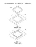
[0005]Referring to FIG. 1 and FIG. 2, an exploded and isometric view, and an assembly isometric view of the prior art are shown, a heat conduction structure includes a metal plate 10a and a plurality of heat pipes 20a. The metal plate 10a defines a plurality of channels 11a. The heat pipes 20a are correspondingly received in the channels 11a. The heat problem of the heat generating device with high power is solved by the high thermal conductivity of the heat pipes 20a.
[0006]Since the metal plate 10a defines the channels 11a corresponding to the heat pipes 20a, and if the area of the heat source is changed, this heat dissipating device can not change the size to match the heat source. Therefore, this heat conduction structure can only be used for the special heat generating element. Further, the heat pipes 20a are received in the channels 11a, and the channel 11a is an enclosed area. This area is not conducive to heat dissipating.
[0007]Therefore, how to change of the heat dissipating device and the heat conduction structure with different heat generating elements to enhance the thermal conductivity of heat conduction structure is come to be a problem.
BRIEF SUMMARY
[0008]The present invention relates to a heat conduction structure. The heat emitting sections of the heat pipes are positioned in the heat dissipating passages. Therefore, the heat conduction structure may dissipate heat by outer winds blowing to the heat emitting sections.
[0009]The heat conduction structure of the present invention includes a first heat conduction plate, a second heat conduction plate and at least one heat pipes. The second heat conduction plate is positioned below the first heat conduction plate. A pair of walls extends from two opposite edges of the second heat conduction plate. The walls connect to a bottom surface of the first heat conduction plate. A receiving space is defined between the first heat conduction plate and the second heat conduction plate. At least one heat pipe is arranged in the receiving space and sandwiched between the first heat conduction plate and the second heat conduction plate. Each heat pipe has a heat absorbing section and a plurality of heat emitting sections extending from each heat absorbing section. A plurality of heat dissipating passages is defined between the at least one heat pipe and the walls. The heat emitting sections are partially positioned in the heat dissipating passages.
[0010]The present invention relates to a heat dissipating device. At least one heat pipe is disposed in the receiving space and sandwiched between the first heat conduction plate and the second heat conduction plate. The number of the at least one heat pipe can be configured to increase or reduce depending on the heat area size of the heat generating element. A best heat dissipating efficiency of the heat dissipating device can be achieved.
[0011]The present invention also relates to a heat dissipating device. The heat emitting sections are disposed in the heat dissipating passages. The airflow from the fan can flow through the heat dissipating passages to improve the heat dissipating efficiency of the heat dissipating device.
[0012]The present invention relates to a heat dissipating device. The heat dissipating device includes a heat conduction structure, a heat dissipating body and a fan. The heat conduction structure includes a first heat conduction plate, a second heat conduction plate and at least one heat pipes. The second heat conduction plate is positioned below the first heat conduction plate. A pair of walls extends from two opposite edges of the second heat conduction plate. The walls connect to a bottom surface of the first heat conduction plate. A receiving space is defined between the first heat conduction plate and the second heat conduction plate. At least one heat pipe is arranged in the receiving space and sandwiched between the first heat conduction plate and the second heat conduction plate. Each heat pipe has a heat absorbing section and a plurality of heat emitting sections extending from each heat absorbing section. A plurality of heat dissipating passages is defined between the at least one heat pipe and the walls. The heat emitting sections are partially positioned in the heat dissipating passages. The heat dissipating body connects to a top surface of the first heat conduction plate. The fan is disposed at a lateral surface of the heat conduction structure and connected thereto
BRIEF DESCRIPTION OF THE DRAWINGS
[0013]These and other features and advantages of the various embodiments disclosed herein will be better understood with respect to the following description and drawings, in which like numbers refer to like parts throughout, and in which:
[0014]FIG. 1 is an exploded and isometric view of a heat conducting structure of the prior art;
[0015]FIG. 2 is an assembly view of FIG. 1;
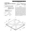
[0016]FIG. 3 is an exploded and isometric view of a heat conducting structure of the present invention;
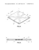
[0017]FIG. 4 is an assembly and perspective view of the heat conducting structure of the present invention;
[0018]FIG. 5 is a cross-sectional view along A-A direction of FIG. 4;
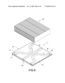
[0019]FIG. 6 is an exploded and isometric view of a heat dissipating device of the present invention;
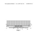
[0020]FIG. 7 is a lateral sectional view of a first embodiment of the present invention;
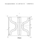
[0021]FIG. 8 shows a working state of the first embodiment of the present invention;
[0022]FIG. 9 shows a working state of a second embodiment of the present invention; and
[0023]FIG. 10 is a top sectional view of a third embodiment of the present invention.
DETAILED DESCRIPTION
[0024]Referring to FIG. 3 to FIG. 5, an exploded view, an assembly view, cross-sectional view along A-A direction of a heat conducting structure of the present invention are shown, the present invention relates to a heat conduction structure, the heat conduction structure includes a first heat conduction plate 10, a second heat plate 20 and at least one heat pipes 30.
[0025]The first heat conduction plate 10 has a rectangular configuration. Two through holes 11 are defined in opposite corners of the first heat conduction plate 10.
[0026]The second heat conduction plate 20 is arranged below the first heat conduction plate 10. The second heat conduction plate 20 has a rectangular configuration. Two walls 21 extend from opposite edges of the second heat conduction plate 20. Each wall 21 is connected to a bottom portion of the first heat conduction plate 10. A receiving space "a" is defined between the first heat conduction plate 10 and the second heat conduction plate 20. Two through holes 22 are defined in the second heat conduction plate 20 corresponding to the through holes 11. The first heat conduction plate 10 and the second heat conduction plate 20 can be mounted by a plurality of fasteners extending through the through holes 11 and the corresponding through holes 22.
[0027]At least three heat pipes 30 are used in the first embodiment of the present invention. The heat pipes 30 are arranged in the receiving space "a", and sandwiched between the first heat conduction plate 10 and the second heat conduction plate 20. Each heat pipe 30 includes a heat absorbing section 31 and a heat emitting section 32 extending from each heat absorbing section 31. A plurality of heat dissipating passages "b" is formed between the heat emitting sections 32 and the walls 21. Each heat emitting section 32 is partially positioned in the heat dissipating passages "b". Each heat pipe 30 has a tabular configuration.
[0028]Referring also to FIG. 6 to FIG. 7, an exploded view of a heat dissipating device of the present invention, and a lateral sectional view of the first embodiment of the present invention are shown. The heat dissipating device further includes a heat dissipating body 40 and a fan 50 (shown in FIG. 10). The heat dissipating body 40 is attached to the surface of the first heat conduction plate 10. A bottom surface of the second heat conduction plate 20 is attached to a heat generating element 61 of a circuit board 60. Heat generated from the heat generating element 61 can be conducted to the first heat conduction plate 10 and to the outer surroundings by the heat pipe 30.
[0029]Referring also to FIG. 8, a working state of the first embodiment of the present invention is shown. In the first embodiment, the heat pipes 30 include two wave-shaped heat pipes and an "I"-shaped heat pipe. These three heat pipes 30 are aligned in a horizontal direction. The heat pipes 30 are positioned on top of the heat generating element 61. The heat pipes 30 cover the heat area of the heat generating element 61 completely. The heat can be absorbed by the heat absorbing sections 31 of the heat pipes 30 which cover on the heat area of the heat generating element 61. The heat then can be dissipated by being conducted to the heat emitting section 32 away from the heat generating element 61.
[0030]Referring also to FIG. 9, a working state of a second embodiment of the present invention is shown. In the second embodiment, the heat pipes 30 include two wave-shaped heat pipes and two "I"-shaped heat pipes aligned between the two wave-shaped heat pipes. The alignment manner of these heat pipes can be configured by the size of the heat generating element 61.
[0031]If the heat generating element 61 has large heat area, the number of the "I"-shaped heat pipe can be increased between the two wave-shaped heat pipes. In this way, the heat dissipating device can adapt to heat generating elements 61 with different sizes.
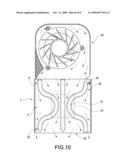
[0032]Referring to FIG. 10, a top sectional view of a third embodiment of the present invention is shown. This heat dissipating device includes a fan 50 disposed at a lateral side of the heat conduction structure 1 and connected thereto. The airflow generated from the fan 50 flows into the heat dissipating passage "b" to dissipate heat from the heat emitting sections 32 of the heat pipes 30. Therefore, the heat conducting efficiency of the heat conduction structure is improved. The whole heat dissipating device can be dissipated. The heat dissipating device can produce the best heat dissipating efficiency.
[0033]The heat dissipating device and the heat conduction structure of present invention has the following advantages: First, the heat pipes 30 are sandwiched between the first heat conduction plate 10 and the second heat conduction plate 20. The arrangement of the heat pipes 30 can be configured by the size of the heat generating element 61. Therefore, the heat dissipating device and the heat conduction structure thereof may adapt to the heat generating elements 61 with different specs. Second, the heat pipes 30 are sandwiched between the first heat conduction plate 10 and the second heat conduction plate 20. The heat conducting plates do not need to be remanufactured. Therefore, the manufacture cost can be saved. Third, the heat conduction structure 1 has a plurality of heat dissipating passages "b" communicating to outside. The heat conduction structure 1 can conduct heat as well as dissipating heat at the same time. The heat dissipating device can produce the best heat dissipating efficiency through the heat conduction structure. Four, the first heat conduction plate 10 and the second heat conduction plate 20 are all configured to sheet plates. Each heat pipe 30 has a tabular configuration to configure the heat conduction structure to a thin-type. The thickness of the heat conduction structure 1 is reduced, so that the volume occupied by the heat dissipating device is reduced.
[0034]The above description is given by way of example, and not limitation. Given the above disclosure, one skilled in the art could devise variations that are within the scope and spirit of the invention disclosed herein, including configurations ways of the recessed portions and materials and/or designs of the attaching structures. Further, the various features of the embodiments disclosed herein can be used alone, or in varying combinations with each other and are not intended to be limited to the specific combination described herein. Thus, the scope of the claims is not to be limited by the illustrated embodiments.
Claims:
1. A heat conduction structure comprises:a first heat conduction plate;a
second heat conduction plate positioned below the first heat conduction
plate, a pair of walls extending from two opposite edges of the second
heat conduction plate, the walls connecting to a bottom surface of the
first heat conduction plate, a receiving space being defined between the
first heat conduction plate and the second heat conduction plate; andat
least one heat pipe arranged in the receiving space and sandwiched
between the first heat conduction plate and the second heat conduction
plate, each heat pipe having a heat absorbing section and a plurality of
heat emitting sections extending from each heat absorbing section, a
plurality of heat dissipating passages being defined between the at least
one heat pipe and the walls, the heat emitting sections being partially
positioned in the heat dissipating passages.
2. The heat conduction structure as claimed in claim 1, wherein the first heat conduction plate and the second heat conduction plate both have a rectangle configuration.
3. The heat conduction structure as claimed in claim 1, wherein two first through holes are defined in opposite corners of the first heat conduction plate, two second through holes are defined in the second heat conduction plate corresponding to the two first through holes, and the first through holes and the second through holes are adapted to receive a plurality of fasteners.
4. The heat conduction structure as claimed in claim 1, wherein the at least one heat pipes comprises three heat pipes.
5. The heat conduction structure as claimed in claim 1, wherein the at least one heat pipe has a wave-shaped and tabular configuration.
6. The heat conduction structure as claimed in claim 1, wherein the at least one heat pipe has an "I"-shaped and tabular configuration.
7. A heat dissipating device comprising:a heat conduction structure comprisinga first heat conduction plate;a second heat conduction plate positioned below the first heat conduction plate, a pair of walls extending from two opposite edges of the second heat conduction plate, the walls connecting to a bottom surface of the first heat conduction plate, a receiving space being defined between the first heat conduction plate and the second heat conduction plate; andat least one heat pipe arranged in the receiving space and sandwiched between the first heat conduction plate and the second heat conduction plate, each heat pipe having a heat absorbing section and a plurality of heat emitting sections extending from each heat absorbing section, a plurality of heat dissipating passages being defined between the at least one heat pipe and the walls, the heat emitting sections being partially positioned in the heat dissipating passages;a heat dissipating body connecting to a top surface of the first heat conduction plate; anda fan disposed at a lateral surface of the heat conduction structure and connected thereto.
8. The heat dissipating device as claimed in claimed 7, wherein the first heat conduction plate and the second heat conduction plate both have a rectangle configuration.
9. The heat dissipating device as claimed in claimed 7, wherein two first through holes are defined in opposite corners of the first heat conduction plate, two second through holes are defined in the second heat conduction plate corresponding to the two first through holes, and the first through holes and the second through holes are adapted to receive a plurality of fasteners.
10. The heat dissipating device as claimed in claimed 7, wherein the at least one heat pipes comprises three heat pipes.
11. The heat dissipating device as claimed in claimed 7, wherein the at least one heat pipe has a wave-shaped and tabular configuration.
12. The heat dissipating device as claimed in claimed 7, wherein the at least one heat pipe has an "I"-shaped and tabular configuration.
Description:
BACKGROUND
[0001]The present invention relates to a heat conduction structure, especially to a heat dissipating device with heat dissipating passages and the heat conduction structure thereof.
[0002]Generally, a heat dissipating device is attached to a heat generating elements with direct contact, and a contact surface of the heat dissipating device is always made of metal with good thermal conductivity. Heat can be rapidly conducted from a heat generating element to the fins of the heat dissipating device.
[0003]Recently, with the development of the computer, the operating speed of the elements inside the computer is greatly improved, and the heat from per unit area is greatly enhanced accordingly. The metal for thermal conduction is less used due to its insufficient thermal efficiency.
[0004]A heat pipe and a vapor chamber are developed afterwards. However, the heat pipe can only provide thermal conduction by a manner of linear contact. The vapor chamber can provide thermal conduction by a manner of surface contact.
[0005]Referring to FIG. 1 and FIG. 2, an exploded and isometric view, and an assembly isometric view of the prior art are shown, a heat conduction structure includes a metal plate 10a and a plurality of heat pipes 20a. The metal plate 10a defines a plurality of channels 11a. The heat pipes 20a are correspondingly received in the channels 11a. The heat problem of the heat generating device with high power is solved by the high thermal conductivity of the heat pipes 20a.
[0006]Since the metal plate 10a defines the channels 11a corresponding to the heat pipes 20a, and if the area of the heat source is changed, this heat dissipating device can not change the size to match the heat source. Therefore, this heat conduction structure can only be used for the special heat generating element. Further, the heat pipes 20a are received in the channels 11a, and the channel 11a is an enclosed area. This area is not conducive to heat dissipating.
[0007]Therefore, how to change of the heat dissipating device and the heat conduction structure with different heat generating elements to enhance the thermal conductivity of heat conduction structure is come to be a problem.
BRIEF SUMMARY
[0008]The present invention relates to a heat conduction structure. The heat emitting sections of the heat pipes are positioned in the heat dissipating passages. Therefore, the heat conduction structure may dissipate heat by outer winds blowing to the heat emitting sections.
[0009]The heat conduction structure of the present invention includes a first heat conduction plate, a second heat conduction plate and at least one heat pipes. The second heat conduction plate is positioned below the first heat conduction plate. A pair of walls extends from two opposite edges of the second heat conduction plate. The walls connect to a bottom surface of the first heat conduction plate. A receiving space is defined between the first heat conduction plate and the second heat conduction plate. At least one heat pipe is arranged in the receiving space and sandwiched between the first heat conduction plate and the second heat conduction plate. Each heat pipe has a heat absorbing section and a plurality of heat emitting sections extending from each heat absorbing section. A plurality of heat dissipating passages is defined between the at least one heat pipe and the walls. The heat emitting sections are partially positioned in the heat dissipating passages.
[0010]The present invention relates to a heat dissipating device. At least one heat pipe is disposed in the receiving space and sandwiched between the first heat conduction plate and the second heat conduction plate. The number of the at least one heat pipe can be configured to increase or reduce depending on the heat area size of the heat generating element. A best heat dissipating efficiency of the heat dissipating device can be achieved.
[0011]The present invention also relates to a heat dissipating device. The heat emitting sections are disposed in the heat dissipating passages. The airflow from the fan can flow through the heat dissipating passages to improve the heat dissipating efficiency of the heat dissipating device.
[0012]The present invention relates to a heat dissipating device. The heat dissipating device includes a heat conduction structure, a heat dissipating body and a fan. The heat conduction structure includes a first heat conduction plate, a second heat conduction plate and at least one heat pipes. The second heat conduction plate is positioned below the first heat conduction plate. A pair of walls extends from two opposite edges of the second heat conduction plate. The walls connect to a bottom surface of the first heat conduction plate. A receiving space is defined between the first heat conduction plate and the second heat conduction plate. At least one heat pipe is arranged in the receiving space and sandwiched between the first heat conduction plate and the second heat conduction plate. Each heat pipe has a heat absorbing section and a plurality of heat emitting sections extending from each heat absorbing section. A plurality of heat dissipating passages is defined between the at least one heat pipe and the walls. The heat emitting sections are partially positioned in the heat dissipating passages. The heat dissipating body connects to a top surface of the first heat conduction plate. The fan is disposed at a lateral surface of the heat conduction structure and connected thereto
BRIEF DESCRIPTION OF THE DRAWINGS
[0013]These and other features and advantages of the various embodiments disclosed herein will be better understood with respect to the following description and drawings, in which like numbers refer to like parts throughout, and in which:
[0014]FIG. 1 is an exploded and isometric view of a heat conducting structure of the prior art;
[0015]FIG. 2 is an assembly view of FIG. 1;
[0016]FIG. 3 is an exploded and isometric view of a heat conducting structure of the present invention;
[0017]FIG. 4 is an assembly and perspective view of the heat conducting structure of the present invention;
[0018]FIG. 5 is a cross-sectional view along A-A direction of FIG. 4;
[0019]FIG. 6 is an exploded and isometric view of a heat dissipating device of the present invention;
[0020]FIG. 7 is a lateral sectional view of a first embodiment of the present invention;
[0021]FIG. 8 shows a working state of the first embodiment of the present invention;
[0022]FIG. 9 shows a working state of a second embodiment of the present invention; and
[0023]FIG. 10 is a top sectional view of a third embodiment of the present invention.
DETAILED DESCRIPTION
[0024]Referring to FIG. 3 to FIG. 5, an exploded view, an assembly view, cross-sectional view along A-A direction of a heat conducting structure of the present invention are shown, the present invention relates to a heat conduction structure, the heat conduction structure includes a first heat conduction plate 10, a second heat plate 20 and at least one heat pipes 30.
[0025]The first heat conduction plate 10 has a rectangular configuration. Two through holes 11 are defined in opposite corners of the first heat conduction plate 10.
[0026]The second heat conduction plate 20 is arranged below the first heat conduction plate 10. The second heat conduction plate 20 has a rectangular configuration. Two walls 21 extend from opposite edges of the second heat conduction plate 20. Each wall 21 is connected to a bottom portion of the first heat conduction plate 10. A receiving space "a" is defined between the first heat conduction plate 10 and the second heat conduction plate 20. Two through holes 22 are defined in the second heat conduction plate 20 corresponding to the through holes 11. The first heat conduction plate 10 and the second heat conduction plate 20 can be mounted by a plurality of fasteners extending through the through holes 11 and the corresponding through holes 22.
[0027]At least three heat pipes 30 are used in the first embodiment of the present invention. The heat pipes 30 are arranged in the receiving space "a", and sandwiched between the first heat conduction plate 10 and the second heat conduction plate 20. Each heat pipe 30 includes a heat absorbing section 31 and a heat emitting section 32 extending from each heat absorbing section 31. A plurality of heat dissipating passages "b" is formed between the heat emitting sections 32 and the walls 21. Each heat emitting section 32 is partially positioned in the heat dissipating passages "b". Each heat pipe 30 has a tabular configuration.
[0028]Referring also to FIG. 6 to FIG. 7, an exploded view of a heat dissipating device of the present invention, and a lateral sectional view of the first embodiment of the present invention are shown. The heat dissipating device further includes a heat dissipating body 40 and a fan 50 (shown in FIG. 10). The heat dissipating body 40 is attached to the surface of the first heat conduction plate 10. A bottom surface of the second heat conduction plate 20 is attached to a heat generating element 61 of a circuit board 60. Heat generated from the heat generating element 61 can be conducted to the first heat conduction plate 10 and to the outer surroundings by the heat pipe 30.
[0029]Referring also to FIG. 8, a working state of the first embodiment of the present invention is shown. In the first embodiment, the heat pipes 30 include two wave-shaped heat pipes and an "I"-shaped heat pipe. These three heat pipes 30 are aligned in a horizontal direction. The heat pipes 30 are positioned on top of the heat generating element 61. The heat pipes 30 cover the heat area of the heat generating element 61 completely. The heat can be absorbed by the heat absorbing sections 31 of the heat pipes 30 which cover on the heat area of the heat generating element 61. The heat then can be dissipated by being conducted to the heat emitting section 32 away from the heat generating element 61.
[0030]Referring also to FIG. 9, a working state of a second embodiment of the present invention is shown. In the second embodiment, the heat pipes 30 include two wave-shaped heat pipes and two "I"-shaped heat pipes aligned between the two wave-shaped heat pipes. The alignment manner of these heat pipes can be configured by the size of the heat generating element 61.
[0031]If the heat generating element 61 has large heat area, the number of the "I"-shaped heat pipe can be increased between the two wave-shaped heat pipes. In this way, the heat dissipating device can adapt to heat generating elements 61 with different sizes.
[0032]Referring to FIG. 10, a top sectional view of a third embodiment of the present invention is shown. This heat dissipating device includes a fan 50 disposed at a lateral side of the heat conduction structure 1 and connected thereto. The airflow generated from the fan 50 flows into the heat dissipating passage "b" to dissipate heat from the heat emitting sections 32 of the heat pipes 30. Therefore, the heat conducting efficiency of the heat conduction structure is improved. The whole heat dissipating device can be dissipated. The heat dissipating device can produce the best heat dissipating efficiency.
[0033]The heat dissipating device and the heat conduction structure of present invention has the following advantages: First, the heat pipes 30 are sandwiched between the first heat conduction plate 10 and the second heat conduction plate 20. The arrangement of the heat pipes 30 can be configured by the size of the heat generating element 61. Therefore, the heat dissipating device and the heat conduction structure thereof may adapt to the heat generating elements 61 with different specs. Second, the heat pipes 30 are sandwiched between the first heat conduction plate 10 and the second heat conduction plate 20. The heat conducting plates do not need to be remanufactured. Therefore, the manufacture cost can be saved. Third, the heat conduction structure 1 has a plurality of heat dissipating passages "b" communicating to outside. The heat conduction structure 1 can conduct heat as well as dissipating heat at the same time. The heat dissipating device can produce the best heat dissipating efficiency through the heat conduction structure. Four, the first heat conduction plate 10 and the second heat conduction plate 20 are all configured to sheet plates. Each heat pipe 30 has a tabular configuration to configure the heat conduction structure to a thin-type. The thickness of the heat conduction structure 1 is reduced, so that the volume occupied by the heat dissipating device is reduced.
[0034]The above description is given by way of example, and not limitation. Given the above disclosure, one skilled in the art could devise variations that are within the scope and spirit of the invention disclosed herein, including configurations ways of the recessed portions and materials and/or designs of the attaching structures. Further, the various features of the embodiments disclosed herein can be used alone, or in varying combinations with each other and are not intended to be limited to the specific combination described herein. Thus, the scope of the claims is not to be limited by the illustrated embodiments.
User Contributions:
Comment about this patent or add new information about this topic:
Images included with this patent application:
 |  |
 |  |
 |  |
 |  |
 |
| Similar patent applications: | |
| Date | Title |
|---|---|
| 2013-06-20 | Heat dissipating fin, heat dissipating device and method of manufacturing the same |
| 2013-04-18 | Heat dissipating structure for light bulb |
| 2013-05-30 | Heat sink with heat bus and fin structure |
| 2013-06-20 | System and method for operating an economizer cycle of an air conditioner |
| 2011-10-27 | Heat dissipation structure |
| New patent applications in this class: | |
| Date | Title |
|---|---|
| 2019-05-16 | Method for preparing porous wick and product prepared by the same |
| 2019-05-16 | Semiconductor device assembly with vapor chamber |
| 2019-05-16 | Straight-through structure of heat dissipation unit |
| 2018-01-25 | Diphasic cooling loop with satellite evaporators |
| 2017-08-17 | Heat pipe |
| Top Inventors for class "Heat exchange" | |
| Rank | Inventor's name |
|---|---|
| 1 | Levi A. Campbell |
| 2 | Chun-Chi Chen |
| 3 | Tai-Her Yang |
| 4 | Robert E. Simons |
| 5 | Richard C. Chu |