Patent application title: VACUUM CLEANER
Inventors:
Im Suk Choi (Incheon, KR)
Assignees:
Daewoo Electronics Corporation
IPC8 Class: AA47L920FI
USPC Class:
134 21
Class name: Cleaning and liquid contact with solids processes including use of vacuum, suction, or inert atmosphere
Publication date: 2009-07-02
Patent application number: 20090165825
uum cleaner. The vacuum cleaner includes a dust
container having an air inlet and an air outlet, a filter inside the dust
container, a case part on the filter, and a dust removing part contacting
an inner side of the filter while being rotated by air introduced into
the dust container through the air inlet. The dust removing part
dislodges dust from the filter while being rotated by the air, thereby
preventing the filter from undergoing functional deterioration.Claims:
1. A vacuum cleaner comprising:a dust container having an air inlet and an
air outlet;a filter disposed inside the dust container;a case part
disposed on the filter; anda dust removing part contacting an inner side
of the filter while being rotated by air introduced into the dust
container through the air inlet.
2. The vacuum cleaner according to claim 1, wherein the dust removing part includes a rotating part rotated by the air flowing into the filter, and a striking part coupled to the rotating part and disposed inside the filter to dislodge dust from the filter.
3. The vacuum cleaner according to claim 2, wherein the rotating part includes a rotating fan rotated by the air flowing into the filter through the air inlet, and a rotational shaft axially coupled to the rotating fan.
4. The vacuum cleaner according to claim 3, wherein the rotating fan is disposed inside the filter.
5. The vacuum cleaner according to claim 3, wherein the rotating fan is disposed outside the filter.
6. The vacuum cleaner according to claim 2, wherein the striking part is made of a soft material.
7. The vacuum cleaner according to claim 1, wherein the case part includes a first case disposed on one side of the filter, and a second case disposed on the other side thereof to secure the filter to the dust container.
8. The vacuum cleaner according to claim 1, wherein the filter includes a supporting member disposed therein to support the filter.
9. The vacuum cleaner according to claim 1, wherein the filter is a HEPA filter.
10. The vacuum cleaner according to claim 1, wherein the filter has a cylindrical shape with a plurality of creases formed along a circumference thereof.
11. The vacuum cleaner according to claim 1, wherein the air inlet has a spiral shape.
12. The vacuum cleaner according to claim 1, wherein the dust removing part includes a rotational shaft rotatably coupled to the case part, and a striking part coupled to the rotational shaft and disposed inside the filter to dislodge dust from the filter while being rotated by the air flowing into the filter.
13. The vacuum cleaner according to claim 12, wherein the striking part includes a rotating fan coupled to the rotational shaft, and a striking member extending from the rotating fan to contact the inner side of the filter.
14. The vacuum cleaner according to claim 13, wherein the striking member is integrally formed with the rotating fan.
15. The vacuum cleaner according to claim 13, wherein the striking member is detachably coupled to the rotating fan.
16. A vacuum cleaner comprising:a dust container comprising an inlet and an outlet, and configured to receive air and dust through the inlet and exhaust the air through the outlet;a wrinkled filter located between the inlet and the outlet, and configured to filter dust while substantially allowing the air to pass therethrough; anda rotary arm duster configured to rotate about an axis and repeatedly hit the wrinkled filter so as to release at least part of dust attached on the wrinkled filter.
17. The vacuum cleaner of claim 16, further comprising a fan rotatable by the air flowing between the inlet and the outlet, wherein the rotary arm duster is engaged with the fan such that the fan rotates the rotary arm duster.
18. The vacuum cleaner of claim 16, wherein the wrinkled filter comprises a wrinkled cylindrical wall defining a hollow space in fluid communication with the dust container, wherein the rotary arm duster is located within the hollow space.
19. A method of vacuum cleaning, the method comprising:vacuum-cleaning a surface using the vacuum cleaner of claim 16; androtating the rotary arm duster such that the rotary arm duster repeatedly hits the wrinkled filter so as to release at least part of dust attached on the wrinkled filter.
20. The method of claim 19, wherein rotating the rotary arm duster while vacuum-cleaning.Description:
CROSS-REFERENCE TO RELATED APPLICATIONS
[0001]This application claims the benefit of Korean Patent Application Nos. 10-2007-0139471, 10-2007-0139472 and 10-2007-0139473 which were filed on Dec. 27, 2007 in the Korean Intellectual Property Office, the disclosure of which is incorporated herein by reference in their entirety. This application is related to and incorporates herein by reference the entire contents of the concurrently filed application entitled "VACUUM CLEANER" (Application No.: ______, Attorney Docket No.: D WAJU.020AUS).
BACKGROUND OF THE INVENTION
[0002]1. Field of the Invention
[0003]The present invention relates to vacuum cleaners, and more particularly to a vacuum cleaner capable of dislodging dust from a filter.
[0004]2. Description of the Related Art
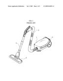
[0005]According to shapes and usage postures, vacuum cleaners can be generally classified into a canister type vacuum cleaner which has a cleaner body configured to be pulled by a user for cleaning, and an upright type vacuum cleaner which has a cleaner body configured to stand upright on the floor. FIGS. 1 and 2 show the canister type vacuum cleaner.
[0006]Referring to FIGS. 1 and 2, a conventional canister type vacuum cleaner includes a cleaner body 1, a suction head 2 serving to suction dust, a hose 3 and an extension pipe 4 disposed between the cleaner body 1 and the suction head 2.
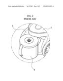
[0007]The cleaner body 1 is formed with a dust container mounting part 5 on which a dust container 6 for receiving dust suctioned through hose 5 is detachably mounted, and includes a fan and a motor (not shown) which generate a suctioning force to collect dust into the dust container 6.
[0008]The dust container 6 is provided with a filter (not shown) which separates foreign substances from air introduced from the suction head 2 such that filtered air can be discharged to the outside through a vent of the cleaner body.
[0009]In a general vacuum cleaner, heavy foreign substances fall to the bottom of the dust container due to gravity, whereas fine dust tends to float in the dust container and is separated from air by the filter to be accumulated in the filter. Thus, when cleaning a place having a great amount of fine dust, the dust drawn into the dust container tends to block the surface of the filter while floating within the dust container, so that the suction force of the motor cannot be efficiently transferred to the suction head. That is, when the fine dust is accumulated on the surface of the filter, the suctioning force is lowered. Therefore, there is a need for a vacuum cleaner that solves the problems of the conventional vacuum cleaner.
SUMMARY OF THE INVENTION
[0010]The present invention is conceived to solve the problems of the conventional technique as described above, and an aspect of the present invention is to provide a vacuum cleaner that can prevent performance deterioration due to dust stuck to a filter.
[0011]According to an aspect of the present invention, a vacuum cleaner includes: a dust container having an air inlet and an air outlet; a filter disposed inside the dust container; a case part disposed on the filter; and a dust removing part contacting an inner side of the filter while being rotated by air introduced into the dust container through the air inlet.
[0012]The dust removing part may include a rotating part rotated by the air flowing into the filter; and a striking part coupled to the rotating part and disposed inside the filter to dislodge dust from the filter. The rotating part may include a rotating fan rotated by the air flowing into the filter through the air inlet, and a rotational shaft axially coupled to the rotating fan. The rotating fan may be disposed inside the filter or outside the filter. The striking part may be made of a soft material.
[0013]The case part may include a first case disposed on one side of the filter and a second case disposed on the other side thereof to secure the filter to the dust container.
[0014]The filter may include a supporting member disposed therein to support the filter.
[0015]The filter may be a HEPA filter.
[0016]The filter may have a cylindrical shape with a plurality of creases formed along a circumference thereof.
[0017]The air inlet may have a spiral shape.
[0018]The dust removing part may include a rotational shaft rotatably coupled to the case part; and a striking part coupled to the rotational shaft and disposed inside the filter to dislodge dust from the filter while being rotated by the air flowing into the filter. The striking part may include a rotating fan coupled to the rotational shaft and a striking member extending from the rotating fan to contact the inner side of the filter. The striking member may be integrally formed with the rotating fan or detachably coupled to the rotating fan.
BRIEF DESCRIPTION OF THE DRAWINGS
[0019]The above and other aspects, features and advantages of the present invention will become apparent from the following description of a preferred embodiment given in conjunction with the accompanying drawings, in which:
[0020]FIGS. 1 and 2 are views of a conventional vacuum cleaner;
[0021]FIG. 3 is a cross-sectional view of a part of a vacuum cleaner according to an embodiment of the present invention;
[0022]FIG. 4 is an exploded perspective view of the part of the vacuum cleaner shown in FIG. 3;
[0023]FIG. 5 is a cross-sectional view taken along line V-V of FIG. 3;
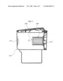
[0024]FIG. 6 is a cross-sectional view of a part of a vacuum cleaner according to another embodiment of the present invention;
[0025]FIG. 7 is a cross-sectional view taken along line VII-VII of FIG. 6;
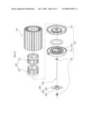
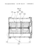
[0026]FIG. 8 is an exploded perspective view of a part of a vacuum cleaner according to a further embodiment of the present invention; and
[0027]FIG. 9 is a cross-sectional view of the part of the vacuum cleaner according to the further embodiment of the present invention.
DETAILED DESCRIPTION OF THE EMBODIMENT
[0028]Exemplary embodiments of the present invention will be described in detail with reference to the accompanying drawings. Herein, a canister type vacuum cleaner will be described for convenience of description. The drawings may be exaggerated in thickness of lines or scale of components for the purpose of descriptive convenience and clarity only. Furthermore, terms used herein should be defined in consideration of functions of components of the present invention and thus can be changed according to the custom or intention of users or operators. Therefore, definition of such terms should be determined according to overall disclosures set forth herein.
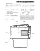
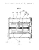
[0029]FIG. 3 is a cross-sectional view of a part of a vacuum cleaner according to an embodiment of the invention, FIG. 4 is an exploded perspective view of the part of the vacuum cleaner shown in FIG. 3, and FIG. 5 is a cross-sectional view taken along line V-V of FIG. 3.
[0030]Referring to FIGS. 3 to 5, the vacuum cleaner according to one embodiment of the invention includes a cleaner body (not shown), a dust container 110, a filter 120, a case part 130, and a dust removing part 100.
[0031]The cleaner body is formed with a suction port and an exhaust port, and is provided with a fan and a motor which generate a suction force. These configurations are apparent to those skilled in the art and a detailed description thereof will be omitted herein.
[0032]The dust container 110 is disposed within the cleaner body so as to communicate with the suction port and the exhaust port. The dust container 110 serves to collect foreign substances from air introduced into the dust container 110 through the suction port, and is detachably mounted to the cleaner body. The dust container 110 is formed with an air inlet 112 communicating with the suction port, and an air outlet 114 communicating with the exhaust port. The air inlet 112 of the dust container may be formed in a spiral shape to cause air flowing into the dust container 110 to generate a cyclonic airstream within the dust container 110.
[0033]The filter 120 is located within the dust container 110. When introduced into the dust container 110 through the air inlet 112 from the outside, air passes through the filter 120 and is then exhausted outside through the exhaust port of the cleaner body. The filter 120 separates foreign substance from the air flowing into the dust container 110 such that only fresh air can be discharged outside the vacuum cleaner through the exhaust port. According to one embodiment of the invention, the filter 120 has a cylindrical shape with a plurality of creases formed along the circumference thereof. Further, the filter 120 may comprise a high efficiency particulate air (HEPA) filter which can effectively remove fine dust from air.
[0034]The case part 130 is provided to the filter 120. The case part 130 is provided to either open side of the filter 120 to connect and secure the filter 120 to the dust container 110. The case part 130 includes a first case 132 provided to one side of the filter 120 and a second case 134 provided to the other side of the filter 120. The first case 132 supports the one side of the filter 120 while blocking the one side of the filter 120 to prevent air from being introduced from the dust container 110 into the filter 120. The second case 134 supports the other side of the filter 120 and secures the filter 120 to the dust container 110. The second case 134 is formed with a discharge port 134a which communicates with the interior of the filter 120. The second case 134 is coupled to a lateral side of the dust container 110 with the air outlet 114 formed thereon to secure the filter 120 to the dust container 110. The discharge port 134a is in communication with the air outlet 114 such that air is discharged from the interior of the filter 120 to the outside of the dust container through the discharge port 134a and the air outlet 114.
[0035]A supporting member 160 is disposed inside the filter 120 to support the filter 120. In this embodiment, the supporting member 160 is divided into two members 162 and 164 which are separated from each other. This configuration serves to secure a space for receiving a striking part 150 described below. The supporting members 162 and 164 are respectively coupled to the first and second, cases 132 and 134 to support the inner side of the filter 120. In this embodiment, the supporting member 160 is described as being divided into the two members, but the present invention is not limited to this configuration. That is, the supporting member may be an integral member or may be divided into three or more members. In this manner, the supporting member can be modified in various shapes.
[0036]The dust removing part 100 is rotated by air introduced into the dust container through the air inlet 112 while contacting the inner side of the filter 120, thereby dislodging dust from the filter 120. The dust removing part 100 includes a rotating part 140 rotated by the air flowing into the filter 120, and a striking part 150 coupled to the rotating part 140 and disposed inside the filter 120 to dislodge dust from the filter 120.
[0037]The rotating part 140 is rotated by the air flowing into the filter 120 through the air inlet 112. The rotating part 140 includes a rotating fan 144 rotated by the air flowing into the filter 120 through the air inlet 112, and a rotational shaft 142 axially coupled to the rotating fan 144.
[0038]The rotating shaft 142 is rotatably provided to the case part 130. Each of the first and second cases 132 and 134 is provided with a bearing 136 which rotatably supports the rotational shaft 142 of the rotating part 140.
[0039]In one embodiment of the invention, the rotating fan 144 is disposed inside the filter 120. The rotating fan 144 is rotated by the air flowing into the filter 120, and the rotational shaft 142 axially coupled to the rotating fan 144 is rotated in connection therewith. In this embodiment, the rotating fan 144 is described as being disposed inside the filter 120, but the present invention can be realized in various modifications. For example, the rotating fan 144 may be disposed outside the filter 120.
[0040]In this embodiment, the striking part 150 is disposed inside the filter 120. One side of the striking part 150 is coupled to the rotational shaft 142, and the other side thereof is disposed to contact the inner side of the filter 120. While being rotated in connection with the rotation of the rotational shaft 142, the striking part 150 hits the creased inner side of the filter 120. Then, the filter 120 can be vibrated to allow fine dust accumulated on the inner or outer side of the filter 120 to be dislodged from the filter 120. The striking part 150 may be formed of a soft material such as PVC and the like to alleviate damage to the filter 120 during hitting.
[0041]The dust removing part 100 is described as including a single striking part 150 in this embodiment, but can be modified in various forms to include two or more striking parts.
[0042]Next, operation of the vacuum cleaner according to the present invention will be described in detail.
[0043]During operation of the vacuum cleaner, air is introduced into the dust container 110 through the suction port via a suction head, an extension pipe, and a suction hose of the vacuum cleaner. Since the configurations of the suction head, the extension pipe and the suction hose connected to the suction port are the same as those of a conventional vacuum cleaner, a detailed description thereof will be omitted herein.
[0044]Air flowing into the dust container 110 generates a cyclonic airstream while passing through the air inlet 112. Among foreign substances contained in the air, heavy substances are agglomerated and fall to the bottom of the dust container 110 while moving inside the dust container 110 by the cyclonic airstream, and fine dust is separated from the air by the filter 120 and accumulated thereon. In this manner, after being separated from such heavy foreign substances, air is separated from the fine dust through the filter 120 and is then discharged to the exhaust port.
[0045]On the other hand, the air flowing into the filer 120 rotates the rotating fan 144, which in turn rotates the rotational shaft 142. At this time, the striking part 150 coupled to the rotational shaft 142 is rotated therewith and hits the creased inner wall of the filter 120. Hence, an impact is imposed on the filter 120 to cause fine dust accumulated on the filter 120 to be dislodged therefrom.
[0046]As described above, since the fine dust accumulated on the filter 120 is automatically dislodged therefrom by the air introduced into the dust container 110, the vacuum cleaner according to this embodiment can prevent a decrease of the suction force caused by the fine dust and is free from inconvenience of frequently cleaning the filter 120.
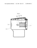
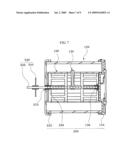
[0047]FIG. 6 is a cross-sectional view of a part of a vacuum cleaner according to another embodiment of the present invention, and FIG. 7 is a cross-sectional view taken along line VII-VII of FIG. 6. Hereinafter, the vacuum cleaner according to this embodiment will be described. Herein, the same components as or similar components to those of the above embodiment will be indicated by the same reference numerals, and a repetitious description thereof will be omitted.
[0048]Referring to FIGS. 6 and 7, a rotating fan 244 of a rotating part 240 is disposed outside a filter 120. A rotational shaft 242 penetrates a first case 232 of a case part 230 and extends outside the filter 120. The first case 232 is formed with a penetration hole (not indicated by reference numeral) through which the rotational shaft 242 passes. The first case 232 is provided with a bearing 236 disposed in the penetration hole.
[0049]A sealing member 270 may be disposed between the penetration hole of the first case 232 and the bearing 236. The sealing member 270 blocks air and fine dust contained in the air within the dust container 110 from being introduced into the filter 120 through a gap between the penetration hole and the bearing 236.
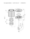
[0050]FIG. 8 is an exploded perspective view of a part of a vacuum cleaner according to a further embodiment of the invention, and FIG. 9 is a cross-sectional view of the part of the vacuum cleaner according to the further embodiment. Herein, the same components as or similar components to those of the above embodiment will be indicated by the same reference numerals, and a repetitious description thereof will be omitted.
[0051]Referring to FIGS. 8 and 9, a dust removing part 300 includes a rotational shaft 340 rotatably coupled to a case 130, and a striking part 350 which removes dust from a filter 120 while being rotated by air flowing into the filter 120.
[0052]The striking part 350 is disposed inside the filter 120. The striking part 350 includes a rotating fan 352 coupled to the rotational shaft 340 and a striking member 354 extending from the rotating fan 352 to contact an inner surface of the filter 120. The rotating fan 352 is disposed inside the filter 120 and coupled to the rotational shaft 340. The striking member 354 extends from the rotating fan 352 to contact the inner side of the filter 120. The striking member 354 is rotated together with the rotating fan 352 and hits the creased inner side of the filter 120 to dislodge fine dust from the filter 120. The striking member 354 may be modified in various forms. For example, the striking member 354 may be integrally formed with the rotating fan 352 or may be detachably coupled thereto. Both the rotating fan 352 and the striking member 354 may also be modified into various forms. For example, both the rotating fan 352 and the striking member 354 may be formed of a soft material, or only the striking member 354 may be formed of a soft material.
[0053]As apparent from the above description, according to an embodiment of the invention, the vacuum cleaner may include a striking part disposed inside a filter to dislodge dust from the filter by hitting the filter, so that a dust container and the vacuum cleaner including the same can be reduced in size.
[0054]Further, according to the embodiment of the invention, the vacuum cleaner may include a dust removing part disposed inside the filter to hit the filter while being rotated, so that dust can be prevented from being accumulated and hardened inside the filter, thereby preventing functional deterioration of the filter by fine dust.
[0055]Further, according to the embodiment of the invention, the vacuum cleaner allows the dust removing part to dislodge dust from the filter while contacting the inner side of the filter, so that dust can be removed from the inner and outer sides of the filter regardless of the shape of the filter.
[0056]Further, according to the embodiment of the invention, the dust removing part is rotated by air flowing into the filter to dislodge the dust from the filer, thereby eliminating requirement for a separate drive unit and preventing energy consumption.
[0057]Further, according to the embodiment of the invention, the vacuum cleaner includes a supporting member which supports the inner side of the filter, thereby enabling semi-permanent use of the filter.
[0058]Further, according to the embodiment of the invention, an air inlet of a dust container has a spiral shape, so that a cyclonic airstream can be generated inside the dust container.
[0059]Further, according to the embodiment of the invention, a striking member is integrally formed with a rotating fan, thereby reducing work effort.
[0060]Further, according to the embodiment of the invention, the striking member is detachably coupled to the rotating fan, so that the striking member alone can be replaced with a new one as needed, thereby reducing cost.
[0061]Further, according to the embodiment of the invention, the vacuum cleaner can remove fine dust from the filter, thereby preventing a reduction of a suction force due to fine dust.
[0062]Although the invention has been described with reference to the embodiments and the accompanying drawings, these are given by way of illustration only, and, it will be apparent to those skilled in the art that various modifications and other equivalent embodiments can be made without departing from the scope of the present invention. In addition, although the present invention has been described with reference to the canister type vacuum cleaner, it should be noted that the canister type vacuum cleaner has been illustrated as an example, and that the present invention may be applied to other vacuum cleaners without being limited thereto. Therefore, the scope and spirit of the invention is limited only by the claims set forth as follows.
Claims:
1. A vacuum cleaner comprising:a dust container having an air inlet and an
air outlet;a filter disposed inside the dust container;a case part
disposed on the filter; anda dust removing part contacting an inner side
of the filter while being rotated by air introduced into the dust
container through the air inlet.
2. The vacuum cleaner according to claim 1, wherein the dust removing part includes a rotating part rotated by the air flowing into the filter, and a striking part coupled to the rotating part and disposed inside the filter to dislodge dust from the filter.
3. The vacuum cleaner according to claim 2, wherein the rotating part includes a rotating fan rotated by the air flowing into the filter through the air inlet, and a rotational shaft axially coupled to the rotating fan.
4. The vacuum cleaner according to claim 3, wherein the rotating fan is disposed inside the filter.
5. The vacuum cleaner according to claim 3, wherein the rotating fan is disposed outside the filter.
6. The vacuum cleaner according to claim 2, wherein the striking part is made of a soft material.
7. The vacuum cleaner according to claim 1, wherein the case part includes a first case disposed on one side of the filter, and a second case disposed on the other side thereof to secure the filter to the dust container.
8. The vacuum cleaner according to claim 1, wherein the filter includes a supporting member disposed therein to support the filter.
9. The vacuum cleaner according to claim 1, wherein the filter is a HEPA filter.
10. The vacuum cleaner according to claim 1, wherein the filter has a cylindrical shape with a plurality of creases formed along a circumference thereof.
11. The vacuum cleaner according to claim 1, wherein the air inlet has a spiral shape.
12. The vacuum cleaner according to claim 1, wherein the dust removing part includes a rotational shaft rotatably coupled to the case part, and a striking part coupled to the rotational shaft and disposed inside the filter to dislodge dust from the filter while being rotated by the air flowing into the filter.
13. The vacuum cleaner according to claim 12, wherein the striking part includes a rotating fan coupled to the rotational shaft, and a striking member extending from the rotating fan to contact the inner side of the filter.
14. The vacuum cleaner according to claim 13, wherein the striking member is integrally formed with the rotating fan.
15. The vacuum cleaner according to claim 13, wherein the striking member is detachably coupled to the rotating fan.
16. A vacuum cleaner comprising:a dust container comprising an inlet and an outlet, and configured to receive air and dust through the inlet and exhaust the air through the outlet;a wrinkled filter located between the inlet and the outlet, and configured to filter dust while substantially allowing the air to pass therethrough; anda rotary arm duster configured to rotate about an axis and repeatedly hit the wrinkled filter so as to release at least part of dust attached on the wrinkled filter.
17. The vacuum cleaner of claim 16, further comprising a fan rotatable by the air flowing between the inlet and the outlet, wherein the rotary arm duster is engaged with the fan such that the fan rotates the rotary arm duster.
18. The vacuum cleaner of claim 16, wherein the wrinkled filter comprises a wrinkled cylindrical wall defining a hollow space in fluid communication with the dust container, wherein the rotary arm duster is located within the hollow space.
19. A method of vacuum cleaning, the method comprising:vacuum-cleaning a surface using the vacuum cleaner of claim 16; androtating the rotary arm duster such that the rotary arm duster repeatedly hits the wrinkled filter so as to release at least part of dust attached on the wrinkled filter.
20. The method of claim 19, wherein rotating the rotary arm duster while vacuum-cleaning.
Description:
CROSS-REFERENCE TO RELATED APPLICATIONS
[0001]This application claims the benefit of Korean Patent Application Nos. 10-2007-0139471, 10-2007-0139472 and 10-2007-0139473 which were filed on Dec. 27, 2007 in the Korean Intellectual Property Office, the disclosure of which is incorporated herein by reference in their entirety. This application is related to and incorporates herein by reference the entire contents of the concurrently filed application entitled "VACUUM CLEANER" (Application No.: ______, Attorney Docket No.: D WAJU.020AUS).
BACKGROUND OF THE INVENTION
[0002]1. Field of the Invention
[0003]The present invention relates to vacuum cleaners, and more particularly to a vacuum cleaner capable of dislodging dust from a filter.
[0004]2. Description of the Related Art
[0005]According to shapes and usage postures, vacuum cleaners can be generally classified into a canister type vacuum cleaner which has a cleaner body configured to be pulled by a user for cleaning, and an upright type vacuum cleaner which has a cleaner body configured to stand upright on the floor. FIGS. 1 and 2 show the canister type vacuum cleaner.
[0006]Referring to FIGS. 1 and 2, a conventional canister type vacuum cleaner includes a cleaner body 1, a suction head 2 serving to suction dust, a hose 3 and an extension pipe 4 disposed between the cleaner body 1 and the suction head 2.
[0007]The cleaner body 1 is formed with a dust container mounting part 5 on which a dust container 6 for receiving dust suctioned through hose 5 is detachably mounted, and includes a fan and a motor (not shown) which generate a suctioning force to collect dust into the dust container 6.
[0008]The dust container 6 is provided with a filter (not shown) which separates foreign substances from air introduced from the suction head 2 such that filtered air can be discharged to the outside through a vent of the cleaner body.
[0009]In a general vacuum cleaner, heavy foreign substances fall to the bottom of the dust container due to gravity, whereas fine dust tends to float in the dust container and is separated from air by the filter to be accumulated in the filter. Thus, when cleaning a place having a great amount of fine dust, the dust drawn into the dust container tends to block the surface of the filter while floating within the dust container, so that the suction force of the motor cannot be efficiently transferred to the suction head. That is, when the fine dust is accumulated on the surface of the filter, the suctioning force is lowered. Therefore, there is a need for a vacuum cleaner that solves the problems of the conventional vacuum cleaner.
SUMMARY OF THE INVENTION
[0010]The present invention is conceived to solve the problems of the conventional technique as described above, and an aspect of the present invention is to provide a vacuum cleaner that can prevent performance deterioration due to dust stuck to a filter.
[0011]According to an aspect of the present invention, a vacuum cleaner includes: a dust container having an air inlet and an air outlet; a filter disposed inside the dust container; a case part disposed on the filter; and a dust removing part contacting an inner side of the filter while being rotated by air introduced into the dust container through the air inlet.
[0012]The dust removing part may include a rotating part rotated by the air flowing into the filter; and a striking part coupled to the rotating part and disposed inside the filter to dislodge dust from the filter. The rotating part may include a rotating fan rotated by the air flowing into the filter through the air inlet, and a rotational shaft axially coupled to the rotating fan. The rotating fan may be disposed inside the filter or outside the filter. The striking part may be made of a soft material.
[0013]The case part may include a first case disposed on one side of the filter and a second case disposed on the other side thereof to secure the filter to the dust container.
[0014]The filter may include a supporting member disposed therein to support the filter.
[0015]The filter may be a HEPA filter.
[0016]The filter may have a cylindrical shape with a plurality of creases formed along a circumference thereof.
[0017]The air inlet may have a spiral shape.
[0018]The dust removing part may include a rotational shaft rotatably coupled to the case part; and a striking part coupled to the rotational shaft and disposed inside the filter to dislodge dust from the filter while being rotated by the air flowing into the filter. The striking part may include a rotating fan coupled to the rotational shaft and a striking member extending from the rotating fan to contact the inner side of the filter. The striking member may be integrally formed with the rotating fan or detachably coupled to the rotating fan.
BRIEF DESCRIPTION OF THE DRAWINGS
[0019]The above and other aspects, features and advantages of the present invention will become apparent from the following description of a preferred embodiment given in conjunction with the accompanying drawings, in which:
[0020]FIGS. 1 and 2 are views of a conventional vacuum cleaner;
[0021]FIG. 3 is a cross-sectional view of a part of a vacuum cleaner according to an embodiment of the present invention;
[0022]FIG. 4 is an exploded perspective view of the part of the vacuum cleaner shown in FIG. 3;
[0023]FIG. 5 is a cross-sectional view taken along line V-V of FIG. 3;
[0024]FIG. 6 is a cross-sectional view of a part of a vacuum cleaner according to another embodiment of the present invention;
[0025]FIG. 7 is a cross-sectional view taken along line VII-VII of FIG. 6;
[0026]FIG. 8 is an exploded perspective view of a part of a vacuum cleaner according to a further embodiment of the present invention; and
[0027]FIG. 9 is a cross-sectional view of the part of the vacuum cleaner according to the further embodiment of the present invention.
DETAILED DESCRIPTION OF THE EMBODIMENT
[0028]Exemplary embodiments of the present invention will be described in detail with reference to the accompanying drawings. Herein, a canister type vacuum cleaner will be described for convenience of description. The drawings may be exaggerated in thickness of lines or scale of components for the purpose of descriptive convenience and clarity only. Furthermore, terms used herein should be defined in consideration of functions of components of the present invention and thus can be changed according to the custom or intention of users or operators. Therefore, definition of such terms should be determined according to overall disclosures set forth herein.
[0029]FIG. 3 is a cross-sectional view of a part of a vacuum cleaner according to an embodiment of the invention, FIG. 4 is an exploded perspective view of the part of the vacuum cleaner shown in FIG. 3, and FIG. 5 is a cross-sectional view taken along line V-V of FIG. 3.
[0030]Referring to FIGS. 3 to 5, the vacuum cleaner according to one embodiment of the invention includes a cleaner body (not shown), a dust container 110, a filter 120, a case part 130, and a dust removing part 100.
[0031]The cleaner body is formed with a suction port and an exhaust port, and is provided with a fan and a motor which generate a suction force. These configurations are apparent to those skilled in the art and a detailed description thereof will be omitted herein.
[0032]The dust container 110 is disposed within the cleaner body so as to communicate with the suction port and the exhaust port. The dust container 110 serves to collect foreign substances from air introduced into the dust container 110 through the suction port, and is detachably mounted to the cleaner body. The dust container 110 is formed with an air inlet 112 communicating with the suction port, and an air outlet 114 communicating with the exhaust port. The air inlet 112 of the dust container may be formed in a spiral shape to cause air flowing into the dust container 110 to generate a cyclonic airstream within the dust container 110.
[0033]The filter 120 is located within the dust container 110. When introduced into the dust container 110 through the air inlet 112 from the outside, air passes through the filter 120 and is then exhausted outside through the exhaust port of the cleaner body. The filter 120 separates foreign substance from the air flowing into the dust container 110 such that only fresh air can be discharged outside the vacuum cleaner through the exhaust port. According to one embodiment of the invention, the filter 120 has a cylindrical shape with a plurality of creases formed along the circumference thereof. Further, the filter 120 may comprise a high efficiency particulate air (HEPA) filter which can effectively remove fine dust from air.
[0034]The case part 130 is provided to the filter 120. The case part 130 is provided to either open side of the filter 120 to connect and secure the filter 120 to the dust container 110. The case part 130 includes a first case 132 provided to one side of the filter 120 and a second case 134 provided to the other side of the filter 120. The first case 132 supports the one side of the filter 120 while blocking the one side of the filter 120 to prevent air from being introduced from the dust container 110 into the filter 120. The second case 134 supports the other side of the filter 120 and secures the filter 120 to the dust container 110. The second case 134 is formed with a discharge port 134a which communicates with the interior of the filter 120. The second case 134 is coupled to a lateral side of the dust container 110 with the air outlet 114 formed thereon to secure the filter 120 to the dust container 110. The discharge port 134a is in communication with the air outlet 114 such that air is discharged from the interior of the filter 120 to the outside of the dust container through the discharge port 134a and the air outlet 114.
[0035]A supporting member 160 is disposed inside the filter 120 to support the filter 120. In this embodiment, the supporting member 160 is divided into two members 162 and 164 which are separated from each other. This configuration serves to secure a space for receiving a striking part 150 described below. The supporting members 162 and 164 are respectively coupled to the first and second, cases 132 and 134 to support the inner side of the filter 120. In this embodiment, the supporting member 160 is described as being divided into the two members, but the present invention is not limited to this configuration. That is, the supporting member may be an integral member or may be divided into three or more members. In this manner, the supporting member can be modified in various shapes.
[0036]The dust removing part 100 is rotated by air introduced into the dust container through the air inlet 112 while contacting the inner side of the filter 120, thereby dislodging dust from the filter 120. The dust removing part 100 includes a rotating part 140 rotated by the air flowing into the filter 120, and a striking part 150 coupled to the rotating part 140 and disposed inside the filter 120 to dislodge dust from the filter 120.
[0037]The rotating part 140 is rotated by the air flowing into the filter 120 through the air inlet 112. The rotating part 140 includes a rotating fan 144 rotated by the air flowing into the filter 120 through the air inlet 112, and a rotational shaft 142 axially coupled to the rotating fan 144.
[0038]The rotating shaft 142 is rotatably provided to the case part 130. Each of the first and second cases 132 and 134 is provided with a bearing 136 which rotatably supports the rotational shaft 142 of the rotating part 140.
[0039]In one embodiment of the invention, the rotating fan 144 is disposed inside the filter 120. The rotating fan 144 is rotated by the air flowing into the filter 120, and the rotational shaft 142 axially coupled to the rotating fan 144 is rotated in connection therewith. In this embodiment, the rotating fan 144 is described as being disposed inside the filter 120, but the present invention can be realized in various modifications. For example, the rotating fan 144 may be disposed outside the filter 120.
[0040]In this embodiment, the striking part 150 is disposed inside the filter 120. One side of the striking part 150 is coupled to the rotational shaft 142, and the other side thereof is disposed to contact the inner side of the filter 120. While being rotated in connection with the rotation of the rotational shaft 142, the striking part 150 hits the creased inner side of the filter 120. Then, the filter 120 can be vibrated to allow fine dust accumulated on the inner or outer side of the filter 120 to be dislodged from the filter 120. The striking part 150 may be formed of a soft material such as PVC and the like to alleviate damage to the filter 120 during hitting.
[0041]The dust removing part 100 is described as including a single striking part 150 in this embodiment, but can be modified in various forms to include two or more striking parts.
[0042]Next, operation of the vacuum cleaner according to the present invention will be described in detail.
[0043]During operation of the vacuum cleaner, air is introduced into the dust container 110 through the suction port via a suction head, an extension pipe, and a suction hose of the vacuum cleaner. Since the configurations of the suction head, the extension pipe and the suction hose connected to the suction port are the same as those of a conventional vacuum cleaner, a detailed description thereof will be omitted herein.
[0044]Air flowing into the dust container 110 generates a cyclonic airstream while passing through the air inlet 112. Among foreign substances contained in the air, heavy substances are agglomerated and fall to the bottom of the dust container 110 while moving inside the dust container 110 by the cyclonic airstream, and fine dust is separated from the air by the filter 120 and accumulated thereon. In this manner, after being separated from such heavy foreign substances, air is separated from the fine dust through the filter 120 and is then discharged to the exhaust port.
[0045]On the other hand, the air flowing into the filer 120 rotates the rotating fan 144, which in turn rotates the rotational shaft 142. At this time, the striking part 150 coupled to the rotational shaft 142 is rotated therewith and hits the creased inner wall of the filter 120. Hence, an impact is imposed on the filter 120 to cause fine dust accumulated on the filter 120 to be dislodged therefrom.
[0046]As described above, since the fine dust accumulated on the filter 120 is automatically dislodged therefrom by the air introduced into the dust container 110, the vacuum cleaner according to this embodiment can prevent a decrease of the suction force caused by the fine dust and is free from inconvenience of frequently cleaning the filter 120.
[0047]FIG. 6 is a cross-sectional view of a part of a vacuum cleaner according to another embodiment of the present invention, and FIG. 7 is a cross-sectional view taken along line VII-VII of FIG. 6. Hereinafter, the vacuum cleaner according to this embodiment will be described. Herein, the same components as or similar components to those of the above embodiment will be indicated by the same reference numerals, and a repetitious description thereof will be omitted.
[0048]Referring to FIGS. 6 and 7, a rotating fan 244 of a rotating part 240 is disposed outside a filter 120. A rotational shaft 242 penetrates a first case 232 of a case part 230 and extends outside the filter 120. The first case 232 is formed with a penetration hole (not indicated by reference numeral) through which the rotational shaft 242 passes. The first case 232 is provided with a bearing 236 disposed in the penetration hole.
[0049]A sealing member 270 may be disposed between the penetration hole of the first case 232 and the bearing 236. The sealing member 270 blocks air and fine dust contained in the air within the dust container 110 from being introduced into the filter 120 through a gap between the penetration hole and the bearing 236.
[0050]FIG. 8 is an exploded perspective view of a part of a vacuum cleaner according to a further embodiment of the invention, and FIG. 9 is a cross-sectional view of the part of the vacuum cleaner according to the further embodiment. Herein, the same components as or similar components to those of the above embodiment will be indicated by the same reference numerals, and a repetitious description thereof will be omitted.
[0051]Referring to FIGS. 8 and 9, a dust removing part 300 includes a rotational shaft 340 rotatably coupled to a case 130, and a striking part 350 which removes dust from a filter 120 while being rotated by air flowing into the filter 120.
[0052]The striking part 350 is disposed inside the filter 120. The striking part 350 includes a rotating fan 352 coupled to the rotational shaft 340 and a striking member 354 extending from the rotating fan 352 to contact an inner surface of the filter 120. The rotating fan 352 is disposed inside the filter 120 and coupled to the rotational shaft 340. The striking member 354 extends from the rotating fan 352 to contact the inner side of the filter 120. The striking member 354 is rotated together with the rotating fan 352 and hits the creased inner side of the filter 120 to dislodge fine dust from the filter 120. The striking member 354 may be modified in various forms. For example, the striking member 354 may be integrally formed with the rotating fan 352 or may be detachably coupled thereto. Both the rotating fan 352 and the striking member 354 may also be modified into various forms. For example, both the rotating fan 352 and the striking member 354 may be formed of a soft material, or only the striking member 354 may be formed of a soft material.
[0053]As apparent from the above description, according to an embodiment of the invention, the vacuum cleaner may include a striking part disposed inside a filter to dislodge dust from the filter by hitting the filter, so that a dust container and the vacuum cleaner including the same can be reduced in size.
[0054]Further, according to the embodiment of the invention, the vacuum cleaner may include a dust removing part disposed inside the filter to hit the filter while being rotated, so that dust can be prevented from being accumulated and hardened inside the filter, thereby preventing functional deterioration of the filter by fine dust.
[0055]Further, according to the embodiment of the invention, the vacuum cleaner allows the dust removing part to dislodge dust from the filter while contacting the inner side of the filter, so that dust can be removed from the inner and outer sides of the filter regardless of the shape of the filter.
[0056]Further, according to the embodiment of the invention, the dust removing part is rotated by air flowing into the filter to dislodge the dust from the filer, thereby eliminating requirement for a separate drive unit and preventing energy consumption.
[0057]Further, according to the embodiment of the invention, the vacuum cleaner includes a supporting member which supports the inner side of the filter, thereby enabling semi-permanent use of the filter.
[0058]Further, according to the embodiment of the invention, an air inlet of a dust container has a spiral shape, so that a cyclonic airstream can be generated inside the dust container.
[0059]Further, according to the embodiment of the invention, a striking member is integrally formed with a rotating fan, thereby reducing work effort.
[0060]Further, according to the embodiment of the invention, the striking member is detachably coupled to the rotating fan, so that the striking member alone can be replaced with a new one as needed, thereby reducing cost.
[0061]Further, according to the embodiment of the invention, the vacuum cleaner can remove fine dust from the filter, thereby preventing a reduction of a suction force due to fine dust.
[0062]Although the invention has been described with reference to the embodiments and the accompanying drawings, these are given by way of illustration only, and, it will be apparent to those skilled in the art that various modifications and other equivalent embodiments can be made without departing from the scope of the present invention. In addition, although the present invention has been described with reference to the canister type vacuum cleaner, it should be noted that the canister type vacuum cleaner has been illustrated as an example, and that the present invention may be applied to other vacuum cleaners without being limited thereto. Therefore, the scope and spirit of the invention is limited only by the claims set forth as follows.
User Contributions:
Comment about this patent or add new information about this topic:
| People who visited this patent also read: | |
| Patent application number | Title |
|---|---|
| 20110103963 | ROTOR BLADE WITH DRAINAGE BORE HOLE |
| 20110103962 | WIND TURBINE BLADE |
| 20110103961 | METHOD OF PRODUCING AN OXIDE DISPERSION STRENGTHENED NICKEL-BASE SUPERALLOY |
| 20110103960 | APPARATUS AND METHOD FOR REDUCING WEAR IN DISK LUGS |
| 20110103959 | Support Spine for a Wind Turbine Blade |
Images included with this patent application:
 |  |
 |  |
 |  |
 |  |
 |  |
| Similar patent applications: | |
| Date | Title |
|---|---|
| 2008-09-18 | Vacuum cleaner equipped with agitator and clutch assembly |
| 2009-10-29 | Vacuum cleaner and method of controlling the same |
| 2010-08-19 | Extendable vacuum cleaner |
| 2010-11-25 | Use of modified open-cell foam materials in vacuum cleaners |
| 2010-12-16 | Use of open-cell foams in vacuum cleaners |
| New patent applications in this class: | |
| Date | Title |
|---|---|
| 2018-01-25 | Systems and methods for treating substrates with cryogenic fluid mixtures |
| 2016-06-16 | Advanced pool cleaner construction |
| 2016-06-09 | Methodologies for rinsing tool surfaces in tools used to process microelectronic workpieces |
| 2016-06-09 | Upright vacuum cleaner with unique airstream path |
| 2016-06-02 | Suction-type cleaner with dedusting control for the filter or filters |
| New patent applications from these inventors: | |
| Date | Title |
|---|---|
| 2009-07-02 | Vacuum cleaner |
| Top Inventors for class "Cleaning and liquid contact with solids" | |
| Rank | Inventor's name |
|---|---|
| 1 | Helmut Jerg |
| 2 | Rodney M. Welch |
| 3 | Barry E. Tuller |
| 4 | Kai Paintner |
| 5 | Michael Rosenbauer |