Patent application title: POWER TOOL HAVING AN ECCENTRIC MASS
Inventors:
Rients Mathijs Bakker (Shanghai, CN)
IPC8 Class: AB24B2300FI
USPC Class:
451357
Class name: Frame or mount portable abrader orbital motion tool
Publication date: 2009-04-30
Patent application number: 20090111364
centric mass for sanding a work surface is
provided. The power tool may include a motor assembly, a sanding shaft,
an eccentric mass, a base element, a fan shaft, a fan, a filter element
and one or more dust channels. The motor assembly may be perpendicular to
the sanding shaft for reducing the height of the power tool and reduce
vibrations transmitted to the operator during use. The fan may be
configured to create a suction force that is guided at least partially
through the dust channels for evacuating at least some of the particulate
matter creating during sanding operations and the filter element may be
configured to capture at least some of the particulate matter for
providing at least some protection to the operator and the fan. The fan
may be position opposite the motor assembly from the sanding shaft.Claims:
1. A power tool comprising:a motor assembly including a motor and a first
shaft, wherein the motor is configured to rotate the first shaft about a
first axis;a second shaft substantially perpendicular to and rotationally
connected to the first shaft such that a rotation of the first shaft
causes a rotation of the second shaft about a second axis;an eccentric
mass coupled to the second shaft such that the rotation of the second
shaft causes a rotation of the eccentric mass;a base element in
communication with the eccentric mass such that the rotation of the
eccentric mass creates a movement of the base element; anda fan
rotationally connected to the first shaft such that the rotation of the
first shaft causes a rotation of the fan about a third axis substantially
perpendicular to the second shaft, wherein the rotation of the fan
creates a suction force in the proximity of the base element.
2. The power tool of claim 1 further comprising a pinion gear and a bevel gear for rotationally connecting the first and second shafts.
3. The power tool of claim 1, wherein the base element includes a sanding surface and the rotation of the eccentric mass creates a vibratory movement of the sanding surface for sanding a work surface.
4. The power tool of claim 3, wherein the rotation of the second shaft additionally creates a rotational movement of the base element for further sanding the work surface.
5. The power tool of claim 3 further comprising one or more dust channels extending from the sanding surface at least partially through the base element toward the fan for at least partially guiding the suction force created by the rotation of the fan.
6. The power tool of claim 5 further comprising a filter element positioned between the fan and the one or more dust channels such that the suction force of the fan draws at least a portion of one or more particulates created during the sanding of the work surface toward the filter element.
7. The power tool of claim 6, wherein the motor, the first shaft, the second shaft, the eccentric mass, the filter element, the fan, and the dust channels do not extend beyond an area defined by the sanding surface.
8. The power tool of claim 1 further comprising a third shaft substantially parallel to and rotationally connected to the first shaft such that a rotation of the first shaft causes the third shaft to rotate about a third axis, wherein the fan is coupled to the third shaft.
9. The power tool of claim 8, wherein both the second shaft and the third shaft are configured to have an operating rotational speed, and wherein the operating rotational speed of the third shaft is higher than the operating rotational speed of the second shaft.
10. The power tool of claim 9, wherein the operating rotational speed of the second shaft is between approximately 6,000 rpm and approximately 12,000 rpm and the operating rotational speed of the third shaft is approximately 20,000 rpm or greater.
11. The power tool of claim 9, wherein the operating rotational speed of the second shaft is between approximately 6,000 rpm and 12,000 rpm and the operating rotational speed of the third shaft is approximately 30,000 rpm or greater.
12. The power tool of claim 8, wherein the third axis is the same as the first axis.
13. A power tool, which removes matter from a work surface in the form of particulates, comprising:a motor assembly including a motor and a first shaft, wherein the motor is configured to rotate the first shaft about a first axis;an eccentric mass rotationally connected to the first shaft such that a rotation of the first shaft causes the eccentric mass to rotate;a base element in communication with the eccentric mass such that the rotation of the eccentric mass creates a movement of the base element;a second shaft rotationally connected to the first shaft;a fan coupled to the second shaft, wherein the rotation of the fan creates a suction force; andone or more dust channels extending from the base element toward the fan for at least partially guiding the suction force away from the base element and toward the fan.
14. The power tool of claim 10, wherein the base element includes a sanding surface and the rotation of the eccentric mass creates a vibratory movement of the sanding surface for sanding the work surface.
15. The power tool of claim 11, wherein the rotation of the first shaft additionally creates a rotational movement of the base element for further sanding the work surface.
16. The power tool of claim 10 further comprising a filter element positioned between the fan and the one or more dust channels for collecting at least a portion of the particulates created during sanding of the work surface.
17. The power tool of claim 13, wherein the second shaft extends through the filter element.
18. The power tool of claim 13, wherein the motor, the first shaft, the second shaft, the eccentric mass, the filter element, the fan, and the dust channels do not extend beyond an area defined by the sanding surface.
19. The power tool of claim 10 further comprising a third shaft substantially perpendicular to and rotationally connected to the first shaft such that a rotation of the first shaft causes the third shaft to rotate about a third axis, and wherein the eccentric mass is coupled to the third shaft.
20. A sander which removes matter from a work surface in the form of one or more particulates comprising:a motor assembly including a motor and a first shaft, wherein the motor is configured to rotate the first shaft about a first axis;a second shaft substantially perpendicular to and rotationally connected to the first shaft such that a rotation of the first shaft causes the second shaft to rotate about a second axis;an eccentric mass coupled to the second shaft such that a rotation of the second shaft causes a rotation of the eccentric mass;a base element in communication with the eccentric mass such that the rotation of the eccentric mass creates a movement of the base element, wherein the base element includes a sanding surface and the rotation of the eccentric mass creates a vibratory movement of the sanding surface for sanding the work surface;a third shaft substantially parallel to and rotationally connected to the first shaft such that a rotation of the first shaft causes the third shaft to rotate about a third axis;a fan coupled to the third shaft such that a rotation of the third shaft rotates the fan about the third axis and creates a suction force in the proximity of the base element;one or more dust channels extending from the sanding surface and at least partially through the base element toward the fan for at least partially guiding the suction force from the sanding surface toward the fan; anda filter element positioned between the fan and the one or more dust channels such that suction force of the fan draws at least a portion of the one more particulates during the sanding of the work surface toward the filter element.
21. The sander of claim 17 further comprising a first pinion gear, a bevel gear, and a second pinion gear for rotationally connecting the first, second, and third shafts.
22. The sander of claim 17 wherein the motor, the first shaft, the second shaft, the third shaft, the eccentric mass, the filter element, the fan, and the one or more dust channels do not extend beyond an area defined by the sanding surface.
23. The sander of claim 17, wherein the rotation of the second shaft additionally creates a rotational movement of the base element for further sanding the work surface.
24. The sander of claim 17, wherein both the second shaft and the third shaft are configured to have an operating rotational speed, and wherein the operating rotational speed of the third shaft is higher than the operating rotational speed of the second shaft.
25. The sander of claim 24, wherein the operating rotational speed of the second shaft is between approximately 6,000 rpm and 12,000 rpm and the operating rotational speed of the third shaft is approximately 20,000 rpm or greater.Description:
BACKGROUND OF THE INVENTION
[0001]1) Field of the Invention
[0002]The present invention relates to power tools.
[0003]2) Description of Related Art
[0004]Power tools such as eccentric sanders are devices used to sand wood and other work surfaces. In a typical eccentric sander, an electric motor rotates a shaft attached to a sanding base at the bottom of the sander. The shaft is also connected to an eccentric weight, which causes the sander to vibrate when the shaft spins. The shaft may further have a fan connected to it in order to suck dust through holes in the sanding base and push it out through a filter mechanism. As the operator moves the sander, the vibrations caused by the eccentric mass create small but rapid movements of the sander, which expedite the sanding of the work surface.
[0005]While known eccentric sanders are useful, the typical sander configuration may have a number of disadvantages. First, the overall size of the sander may be large, particularly in the height dimension, making it cumbersome to control. Second, the sander may require two hands to operate it. Third, the motor and eccentric weight may rotate in the same plane, which may cause a good deal of vibration to be transmitted to the operator. Fourth, by pushing out the dust, the fan blades may come in contact with the dust, which can wear the fan down over time.
[0006]In light of the foregoing, there remains a need for providing an improved power tool.
BRIEF SUMMARY
[0007]Embodiments of the present invention may address one or more of the shortcomings discussed above by providing an improved power tool. For example, according to an embodiment, the power tool provides a motor assembly having a drive shaft that is generally perpendicular to the sanding base. As another example, the power tool may provide a fan for creating a suction force and dust channels for at least partially guiding the suction force from the base element and toward the fan.
[0008]More specifically, according to an embodiment, a power tool may include a motor assembly, a sanding shaft, an eccentric mass, a base element, and a fan. The motor assembly may include a motor and a drive shaft, wherein the motor rotates the drive shaft during operation about a first axis. The sanding shaft may be substantially perpendicular to and rotationally connected to the drive shaft such that a rotation of the drive shaft causes a rotation of the sanding shaft about a second axis. The eccentric mass may be coupled to the sanding shaft such that a rotation of the sanding shaft causes a rotation of the eccentric mass. The base element may be in communication with the eccentric mass such that rotation of the eccentric mass creates a movement of the base element. The fan may be rotationally connected to the drive shaft such that the rotation of the drive shaft causes a rotation of the fan about a third axis substantially perpendicular to the sanding shaft and wherein the rotation of the fan creates a suction force in the proximity of the base element.
[0009]The power tool may further include a pinion gear and a bevel gear to rotationally connect the drive shaft and the sanding shaft.
[0010]The base element may include a sanding surface and the rotation of the eccentric mass may create a vibratory and/or rotational movement of the sanding surface for sanding a work surface.
[0011]The power tool may further include one or more dust channels extending from the base element to the fan for at least partially guiding the suction force created by the fan. Also, the power tool may further include a filter element positioned between the fan and the dust channels, such that the suction force of the fan draws at least a portion of the particulates created during the sanding of the work surface toward the filter element.
[0012]The power tool may further include a fan shaft that is substantially parallel to and rotationally connected to the drive shaft such that rotation of the drive shaft causes a rotation of the fan shaft about a third axis, which is coupled to the fan shaft. Each of the sanding shaft and the fan shaft may have an operating rotational speed. The operating rotational speed for the fan shaft may be higher than the operating rotational speed for the sanding shaft. For example, the operating rotational speed for the fan shaft may be approximately 20,000 rpm, 30,000 rpm, or greater and the operating rotational speed for the sanding shaft may be between approximately 6,000 rpm and approximately 12,000 rpm. The third axis may be the same the first axis.
BRIEF DESCRIPTION OF THE DRAWING
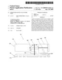
[0013]FIG. 1 is a side cross-sectional schematic view of the power tool according to an embodiment of the invention; and
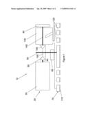
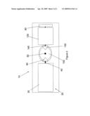
[0014]FIG. 2 is a top schematic view of the power tool of FIG. 1.
DETAILED DESCRIPTION OF THE INVENTION
[0015]The present invention now will be described more fully hereinafter with reference to the accompanying drawings, in which some, but not all embodiments of the invention are shown. Indeed, this invention may be embodied in many different forms and should not be construed as limited to the embodiments set forth herein; rather, these embodiments are provided so that this disclosure will satisfy applicable legal requirements. Like numbers refer to like elements throughout.
[0016]FIG. 1 illustrates a power tool 10 consistent with an exemplary embodiment. The power tool 10 may include a motor assembly 20, a sanding shaft 50, an eccentric mass 60, a base element 70, and a fan 80.
[0017]The motor assembly 20 may include a motor 30 and a drive shaft 40. The motor 30 rotates the drive shaft 40 during operation. The drive shaft 40 is rotationally connected to the sanding shaft 50. As used herein, and in the claims, the phrase "rotationally connected to" means that the elements described each rotate when one of the elements is rotated. This phrase does not necessarily mean that the two elements are directly attached to one another. For example, one or more intermediate elements may lie between the two elements and serve to transfer the rotation. As a specific example and as illustrated in FIG. 1, the power tool 10 may include a pinion gear 90 and a bevel gear 100. The pinion gear 90 may be coupled to the end of the drive shaft 40 which meshes with the bevel gear 100 coupled to the sanding shaft 50. The meshing connection of the pinion gear 90 and the bevel gear 100 transfers the rotation of the drive shaft 40 to the sanding shaft 50. Further, the rotational speed of the two elements may not necessarily be equal. For example, different sized gears may be used to transfer rotation, which may result in one element rotating at a faster speed than the other.
[0018]As shown in FIG. 1, the sanding shaft 50 may lie substantially perpendicular to the drive shaft 40 and thus the motor assembly 20. As used herein, and in the claims, the phrase "substantially perpendicular to" means that the longitudinal axes of the elements described lie at an angle to one another that is approximately ninety degrees. The eccentric mass 60 may be coupled to the sanding shaft 50 such that a rotation of the sanding shaft 50 causes a rotation of the eccentric mass 60. As used herein, and in the claims, the phrase "coupled to" means that there is a physical connection between the elements described. This phrase also contemplates that the elements described may be integrated. The eccentric mass 60 may be a weight which has its center of mass offset from that of its center of rotation.
[0019]By placing the sanding shaft 50, and hence the eccentric mass 60, substantially perpendicular to the motor assembly 20, the movements of the motor assembly 20 and the eccentric mass 60 lie in separate planes. It is believed that the vibratory motions transferred to the operator are be lessened in such a configuration. Also, as shown in FIG. 1, positioning the motor assembly 20 perpendicular to the sanding shaft 50 (referred to as a horizontal motor) allows for a reduce height of the power tool 10 compared to a power tool in which the motor assembly 20 and the sanding shaft are parallel (referred to as a vertical motor). Reducing the height of the power tool 10 lowers the center of mass of the power tool 10 which may make it easier for an operator to control the power tool 10 during operations. For example, in some instances, an operator may be able to operate the power tool 10 with one hand because use of a second hand to stabilize the power tool 10 and prevent it from tipping over may not be required.
[0020]The base element 70 may reside at the bottom of the power tool 10 and contacts the work surface during operation. The base element 70 is in communication with the eccentric mass 60 such that rotation of the eccentric mass 60 creates a movement of the base element 70. As used herein, and in the claims, the phrase "in communication with" means that the elements described are at least indirectly in contact with one another. For example, the eccentric mass 60 may be in communication with the base element 70 through the sanding shaft 50 and a bearing (not illustrated).
[0021]The fan 80 may be rotationally connected to the drive shaft 40. For example and as illustrated, the power tool 10 may further include a fan shaft 140 and a second bevel gear 150. The second bevel gear 150 may be coupled to a first end of the fan shaft 140 and the fan 80 may be coupled to a second end of the fan shaft 140. The rotation of the drive shaft 40 creates a rotation of the fan shaft 140 and thus the fan 80 about an axis substantially perpendicular to that of the sanding shaft 50 through the first bevel gear 90, the pinion gear 100, and the second bevel gear 150. Although the fan shaft 140 of the FIG. 1 is illustrated as a separate shaft from the drive shaft, in other embodiments the fan shaft and the drive shaft may be integrated, e.g., the fan may be coupled to the drive shaft. Also, although the drive shaft and the fan rotate about the same axis, in other embodiments, the axis of rotation of the drive shaft and the fan may differ, e.g., the axes may be parallel but not co-linear or the axes may be perpendicular to one another. The rotation of the fan 80 creates a suction force in the proximity of the base element 70. The suction force may help evacuate particulate matter, such as dust, created by the operation of the power tool 10 on the work surface. By keeping the work surface clear of the particulate matter, the operator may be able to better judge how long the power tool 10 should be used on the work surface.
[0022]For embodiments having a separate fan shaft 140, the fan shaft 140 may be designed to be optimal for spinning the fan 80. For instance, the fan shaft 140 may not need to handle as large of forces as the drive shaft 40, so it could be made of a different material, or sized or shaped differently. Further, the fan shaft 140 may be made of a flexible material to allow the fan shaft 140 to be routed through a curved path. Additional benefits may arise from placing the fan shaft 140 on the opposite side of the sanding shaft 50 from the drive shaft 40 as illustrated in FIG. 1. This configuration keeps the motor assembly 20 from being stacked on top of the dust evacuation components such as the filter element 130 and fan 80. And, as described above, lowering the overall height of the power tool 10 may make it easier to operate.
[0023]Another consideration may be fan speed. The rotation of the sanding shaft 50 may be configured to create an optimal movement of the eccentric mass for a sanding operation. For example, the sanding shaft 50 may have a rotation speed of approximately 6,000 rpm to 12,000 rpm. Therefore, in embodiments where the sanding shaft 50 also drives the fan 80, the fan speed would be approximately 6,000 rpm to 12,000 rpm.
[0024]Although these speeds may be preferred to support the sanding operation, the speeds may be too low to provide enough speed for the fan 80 to create a large enough vacuum force in some instances. For example, in order to create a large enough vacuum or suction force, it may be preferred to have the fan speed at least 20,000 rpm. Or as another example, it may be preferred to have the fan speed at least 30,000 rpm or at least 40,000 rpm. For embodiments having separate fan and sanding shafts 140, 50, the fan speed and the rotation speed of the sanding shaft 50 be differ and both be configured for the optimal spend for creating a suction force and for supporting a sanding operation. For example, the fan shaft 140 may be configured to rotate at 20,000 rpm or greater while the sanding shaft 50 may be configured to rotate between 6,000 rpm and 12,000 rpm. At discussed above, the different shaft speeds may be accomplished through the gear train (e.g., different size gears 90, 100, 150).
[0025]As used in herein, "operating rotational speed" refers to the intended speed of rotation of the fan shaft or sanding shaft when the motor is driving or rotating the drive shaft during operation. For the preceding example, the fan shaft has an operating rotational speed of approximately 20,000 rpm or greater and the sanding shaft has an operating rotational speed between approximately 6,000 rpm to 12,000 rpm.
[0026]Referring back to the base element 70, the base element 70 may include a sanding surface 110. The sanding surface 110 may comprise of sandpaper or another type of coarse material. Due to the coupling of the eccentric mass 60 to the sanding shaft 50, the base element 70 and thus the sanding surface 110 may vibrate in the plane of the work surface during operation. The vibratory movement of the sanding surface 110 against the work surface may cause the removal of particulate matter from the work surface. A power tool 10 using this arrangement may be referred to as a pad sander or a sheet sander.
[0027]The base element 70 may rotate with the sanding shaft 50 in addition to or instead of vibrate. Rotating and vibrating the base element 70 may expedite the sanding of the work surface compared to only vibrating the base element. A power tool 10 having both a vibrating and a rotating base element may be referred to as a random orbital sander.
[0028]The power tool 10 may further include one or more dust channels 120. The dust channels 120 are open conduits or cavities which extend from the sanding surface 110 at least partially through the base element 70 toward the fan 80. The dust channels 120 help to guide the suction force created by the fan 80 from the work surface to the fan and thus facilitates the pulling or sucking of the dust or other particulate matter created by the sanding away from the work surface and toward the fan 80.
[0029]The power tool 10 may also include a filter element 130. For example, the power tool 10 may include a filter element 130 between the dust channels 120 and the fan 80. By placing the filter element 130 between the dust channels 120 and the fan 80, the suction force of the fan 80 creates a vacuum-like pressure within the filter element 130 that draws the dust into the filter element 130 from the work surface. It is believe that the placement of the fan 80 away from the base element 70 and opposite the filter element 130 from the base element 70 is a more efficient manner in removing dust than placing the fan near or directly above the sanding surface where the fan is more likely to push the dust rather than pull the dust. The filter element 130 may include a dust box, foam filter, or any other type of filter known within the art to be suitable for this application. The suction force provided by the fan 80 may move the particulate matter from the work surface, through the dust channels 120, and into the filter element 130 where it is at least partially trapped. The filter element may be detachable from the rest of the power tool to allow the filter element to be cleaned or replaced.
[0030]By trapping dust and other particulates in the filter element 130, the work surface may remain relatively clear, and the expelled air can be cleansed so it is believed that the operator may be at least partially protected from the inhalation of particulate matter. The filter element 130 may also help protect the fan 80 by collecting at least some of the particular matter before such mater reaches the fan 80. Without the filter element more particular matter may reach and degrade the fan overtime.
[0031]As shown in FIG. 2, the motor 30, the drive shaft 40, the sanding shaft 50, the eccentric mass 60, the filter element 130, the fan 80, and the dust channels 120 may be configured to not extend beyond an area defined by the sanding surface 110. As used herein, and in the claims, the phrase "do not extend beyond an area defined by the sanding surface" means that the elements described reside completely above the sanding surface 110. Thus, when viewed from above or below, without any sort of housing in place, the profile of the power tool 10 will be defined by the sanding surface 110. This configuration may decrease the overall size of the power tool 10, which in turn may make the power tool 10 easier to operate. In particular, by keeping the elements of the power tool 10 above the sanding surface 110, the mass of the power tool 10 remains relatively centered over the base element 70 so it is believed that it may be easier to maintain an even pressure across the sanding surface 110, which may result in more even sanding. Further, the smaller size of the power tool 10 may make one-handed operation easier in some instances.
[0032]While the power tool 10 has usually been described in terms of operation as a sander, the power tool 10 may also be usable as a grinder. In particular, the power tool 10 may work well as a grinder when the base element rotates, and when a sanding surface designed for this application is used.
[0033]Many modifications and other embodiments of the invention set forth herein will come to mind to one skilled in the art to which this invention pertains having the benefit of the teachings presented in the foregoing descriptions and the associated drawings. Therefore, it is to be understood that the invention is not to be limited to the specific embodiments disclosed and that modifications and other embodiments are intended to be included within the scope of the appended claims. Although specific terms are employed herein, they are used in a generic and descriptive sense only and not for purposes of limitation.
Claims:
1. A power tool comprising:a motor assembly including a motor and a first
shaft, wherein the motor is configured to rotate the first shaft about a
first axis;a second shaft substantially perpendicular to and rotationally
connected to the first shaft such that a rotation of the first shaft
causes a rotation of the second shaft about a second axis;an eccentric
mass coupled to the second shaft such that the rotation of the second
shaft causes a rotation of the eccentric mass;a base element in
communication with the eccentric mass such that the rotation of the
eccentric mass creates a movement of the base element; anda fan
rotationally connected to the first shaft such that the rotation of the
first shaft causes a rotation of the fan about a third axis substantially
perpendicular to the second shaft, wherein the rotation of the fan
creates a suction force in the proximity of the base element.
2. The power tool of claim 1 further comprising a pinion gear and a bevel gear for rotationally connecting the first and second shafts.
3. The power tool of claim 1, wherein the base element includes a sanding surface and the rotation of the eccentric mass creates a vibratory movement of the sanding surface for sanding a work surface.
4. The power tool of claim 3, wherein the rotation of the second shaft additionally creates a rotational movement of the base element for further sanding the work surface.
5. The power tool of claim 3 further comprising one or more dust channels extending from the sanding surface at least partially through the base element toward the fan for at least partially guiding the suction force created by the rotation of the fan.
6. The power tool of claim 5 further comprising a filter element positioned between the fan and the one or more dust channels such that the suction force of the fan draws at least a portion of one or more particulates created during the sanding of the work surface toward the filter element.
7. The power tool of claim 6, wherein the motor, the first shaft, the second shaft, the eccentric mass, the filter element, the fan, and the dust channels do not extend beyond an area defined by the sanding surface.
8. The power tool of claim 1 further comprising a third shaft substantially parallel to and rotationally connected to the first shaft such that a rotation of the first shaft causes the third shaft to rotate about a third axis, wherein the fan is coupled to the third shaft.
9. The power tool of claim 8, wherein both the second shaft and the third shaft are configured to have an operating rotational speed, and wherein the operating rotational speed of the third shaft is higher than the operating rotational speed of the second shaft.
10. The power tool of claim 9, wherein the operating rotational speed of the second shaft is between approximately 6,000 rpm and approximately 12,000 rpm and the operating rotational speed of the third shaft is approximately 20,000 rpm or greater.
11. The power tool of claim 9, wherein the operating rotational speed of the second shaft is between approximately 6,000 rpm and 12,000 rpm and the operating rotational speed of the third shaft is approximately 30,000 rpm or greater.
12. The power tool of claim 8, wherein the third axis is the same as the first axis.
13. A power tool, which removes matter from a work surface in the form of particulates, comprising:a motor assembly including a motor and a first shaft, wherein the motor is configured to rotate the first shaft about a first axis;an eccentric mass rotationally connected to the first shaft such that a rotation of the first shaft causes the eccentric mass to rotate;a base element in communication with the eccentric mass such that the rotation of the eccentric mass creates a movement of the base element;a second shaft rotationally connected to the first shaft;a fan coupled to the second shaft, wherein the rotation of the fan creates a suction force; andone or more dust channels extending from the base element toward the fan for at least partially guiding the suction force away from the base element and toward the fan.
14. The power tool of claim 10, wherein the base element includes a sanding surface and the rotation of the eccentric mass creates a vibratory movement of the sanding surface for sanding the work surface.
15. The power tool of claim 11, wherein the rotation of the first shaft additionally creates a rotational movement of the base element for further sanding the work surface.
16. The power tool of claim 10 further comprising a filter element positioned between the fan and the one or more dust channels for collecting at least a portion of the particulates created during sanding of the work surface.
17. The power tool of claim 13, wherein the second shaft extends through the filter element.
18. The power tool of claim 13, wherein the motor, the first shaft, the second shaft, the eccentric mass, the filter element, the fan, and the dust channels do not extend beyond an area defined by the sanding surface.
19. The power tool of claim 10 further comprising a third shaft substantially perpendicular to and rotationally connected to the first shaft such that a rotation of the first shaft causes the third shaft to rotate about a third axis, and wherein the eccentric mass is coupled to the third shaft.
20. A sander which removes matter from a work surface in the form of one or more particulates comprising:a motor assembly including a motor and a first shaft, wherein the motor is configured to rotate the first shaft about a first axis;a second shaft substantially perpendicular to and rotationally connected to the first shaft such that a rotation of the first shaft causes the second shaft to rotate about a second axis;an eccentric mass coupled to the second shaft such that a rotation of the second shaft causes a rotation of the eccentric mass;a base element in communication with the eccentric mass such that the rotation of the eccentric mass creates a movement of the base element, wherein the base element includes a sanding surface and the rotation of the eccentric mass creates a vibratory movement of the sanding surface for sanding the work surface;a third shaft substantially parallel to and rotationally connected to the first shaft such that a rotation of the first shaft causes the third shaft to rotate about a third axis;a fan coupled to the third shaft such that a rotation of the third shaft rotates the fan about the third axis and creates a suction force in the proximity of the base element;one or more dust channels extending from the sanding surface and at least partially through the base element toward the fan for at least partially guiding the suction force from the sanding surface toward the fan; anda filter element positioned between the fan and the one or more dust channels such that suction force of the fan draws at least a portion of the one more particulates during the sanding of the work surface toward the filter element.
21. The sander of claim 17 further comprising a first pinion gear, a bevel gear, and a second pinion gear for rotationally connecting the first, second, and third shafts.
22. The sander of claim 17 wherein the motor, the first shaft, the second shaft, the third shaft, the eccentric mass, the filter element, the fan, and the one or more dust channels do not extend beyond an area defined by the sanding surface.
23. The sander of claim 17, wherein the rotation of the second shaft additionally creates a rotational movement of the base element for further sanding the work surface.
24. The sander of claim 17, wherein both the second shaft and the third shaft are configured to have an operating rotational speed, and wherein the operating rotational speed of the third shaft is higher than the operating rotational speed of the second shaft.
25. The sander of claim 24, wherein the operating rotational speed of the second shaft is between approximately 6,000 rpm and 12,000 rpm and the operating rotational speed of the third shaft is approximately 20,000 rpm or greater.
Description:
BACKGROUND OF THE INVENTION
[0001]1) Field of the Invention
[0002]The present invention relates to power tools.
[0003]2) Description of Related Art
[0004]Power tools such as eccentric sanders are devices used to sand wood and other work surfaces. In a typical eccentric sander, an electric motor rotates a shaft attached to a sanding base at the bottom of the sander. The shaft is also connected to an eccentric weight, which causes the sander to vibrate when the shaft spins. The shaft may further have a fan connected to it in order to suck dust through holes in the sanding base and push it out through a filter mechanism. As the operator moves the sander, the vibrations caused by the eccentric mass create small but rapid movements of the sander, which expedite the sanding of the work surface.
[0005]While known eccentric sanders are useful, the typical sander configuration may have a number of disadvantages. First, the overall size of the sander may be large, particularly in the height dimension, making it cumbersome to control. Second, the sander may require two hands to operate it. Third, the motor and eccentric weight may rotate in the same plane, which may cause a good deal of vibration to be transmitted to the operator. Fourth, by pushing out the dust, the fan blades may come in contact with the dust, which can wear the fan down over time.
[0006]In light of the foregoing, there remains a need for providing an improved power tool.
BRIEF SUMMARY
[0007]Embodiments of the present invention may address one or more of the shortcomings discussed above by providing an improved power tool. For example, according to an embodiment, the power tool provides a motor assembly having a drive shaft that is generally perpendicular to the sanding base. As another example, the power tool may provide a fan for creating a suction force and dust channels for at least partially guiding the suction force from the base element and toward the fan.
[0008]More specifically, according to an embodiment, a power tool may include a motor assembly, a sanding shaft, an eccentric mass, a base element, and a fan. The motor assembly may include a motor and a drive shaft, wherein the motor rotates the drive shaft during operation about a first axis. The sanding shaft may be substantially perpendicular to and rotationally connected to the drive shaft such that a rotation of the drive shaft causes a rotation of the sanding shaft about a second axis. The eccentric mass may be coupled to the sanding shaft such that a rotation of the sanding shaft causes a rotation of the eccentric mass. The base element may be in communication with the eccentric mass such that rotation of the eccentric mass creates a movement of the base element. The fan may be rotationally connected to the drive shaft such that the rotation of the drive shaft causes a rotation of the fan about a third axis substantially perpendicular to the sanding shaft and wherein the rotation of the fan creates a suction force in the proximity of the base element.
[0009]The power tool may further include a pinion gear and a bevel gear to rotationally connect the drive shaft and the sanding shaft.
[0010]The base element may include a sanding surface and the rotation of the eccentric mass may create a vibratory and/or rotational movement of the sanding surface for sanding a work surface.
[0011]The power tool may further include one or more dust channels extending from the base element to the fan for at least partially guiding the suction force created by the fan. Also, the power tool may further include a filter element positioned between the fan and the dust channels, such that the suction force of the fan draws at least a portion of the particulates created during the sanding of the work surface toward the filter element.
[0012]The power tool may further include a fan shaft that is substantially parallel to and rotationally connected to the drive shaft such that rotation of the drive shaft causes a rotation of the fan shaft about a third axis, which is coupled to the fan shaft. Each of the sanding shaft and the fan shaft may have an operating rotational speed. The operating rotational speed for the fan shaft may be higher than the operating rotational speed for the sanding shaft. For example, the operating rotational speed for the fan shaft may be approximately 20,000 rpm, 30,000 rpm, or greater and the operating rotational speed for the sanding shaft may be between approximately 6,000 rpm and approximately 12,000 rpm. The third axis may be the same the first axis.
BRIEF DESCRIPTION OF THE DRAWING
[0013]FIG. 1 is a side cross-sectional schematic view of the power tool according to an embodiment of the invention; and
[0014]FIG. 2 is a top schematic view of the power tool of FIG. 1.
DETAILED DESCRIPTION OF THE INVENTION
[0015]The present invention now will be described more fully hereinafter with reference to the accompanying drawings, in which some, but not all embodiments of the invention are shown. Indeed, this invention may be embodied in many different forms and should not be construed as limited to the embodiments set forth herein; rather, these embodiments are provided so that this disclosure will satisfy applicable legal requirements. Like numbers refer to like elements throughout.
[0016]FIG. 1 illustrates a power tool 10 consistent with an exemplary embodiment. The power tool 10 may include a motor assembly 20, a sanding shaft 50, an eccentric mass 60, a base element 70, and a fan 80.
[0017]The motor assembly 20 may include a motor 30 and a drive shaft 40. The motor 30 rotates the drive shaft 40 during operation. The drive shaft 40 is rotationally connected to the sanding shaft 50. As used herein, and in the claims, the phrase "rotationally connected to" means that the elements described each rotate when one of the elements is rotated. This phrase does not necessarily mean that the two elements are directly attached to one another. For example, one or more intermediate elements may lie between the two elements and serve to transfer the rotation. As a specific example and as illustrated in FIG. 1, the power tool 10 may include a pinion gear 90 and a bevel gear 100. The pinion gear 90 may be coupled to the end of the drive shaft 40 which meshes with the bevel gear 100 coupled to the sanding shaft 50. The meshing connection of the pinion gear 90 and the bevel gear 100 transfers the rotation of the drive shaft 40 to the sanding shaft 50. Further, the rotational speed of the two elements may not necessarily be equal. For example, different sized gears may be used to transfer rotation, which may result in one element rotating at a faster speed than the other.
[0018]As shown in FIG. 1, the sanding shaft 50 may lie substantially perpendicular to the drive shaft 40 and thus the motor assembly 20. As used herein, and in the claims, the phrase "substantially perpendicular to" means that the longitudinal axes of the elements described lie at an angle to one another that is approximately ninety degrees. The eccentric mass 60 may be coupled to the sanding shaft 50 such that a rotation of the sanding shaft 50 causes a rotation of the eccentric mass 60. As used herein, and in the claims, the phrase "coupled to" means that there is a physical connection between the elements described. This phrase also contemplates that the elements described may be integrated. The eccentric mass 60 may be a weight which has its center of mass offset from that of its center of rotation.
[0019]By placing the sanding shaft 50, and hence the eccentric mass 60, substantially perpendicular to the motor assembly 20, the movements of the motor assembly 20 and the eccentric mass 60 lie in separate planes. It is believed that the vibratory motions transferred to the operator are be lessened in such a configuration. Also, as shown in FIG. 1, positioning the motor assembly 20 perpendicular to the sanding shaft 50 (referred to as a horizontal motor) allows for a reduce height of the power tool 10 compared to a power tool in which the motor assembly 20 and the sanding shaft are parallel (referred to as a vertical motor). Reducing the height of the power tool 10 lowers the center of mass of the power tool 10 which may make it easier for an operator to control the power tool 10 during operations. For example, in some instances, an operator may be able to operate the power tool 10 with one hand because use of a second hand to stabilize the power tool 10 and prevent it from tipping over may not be required.
[0020]The base element 70 may reside at the bottom of the power tool 10 and contacts the work surface during operation. The base element 70 is in communication with the eccentric mass 60 such that rotation of the eccentric mass 60 creates a movement of the base element 70. As used herein, and in the claims, the phrase "in communication with" means that the elements described are at least indirectly in contact with one another. For example, the eccentric mass 60 may be in communication with the base element 70 through the sanding shaft 50 and a bearing (not illustrated).
[0021]The fan 80 may be rotationally connected to the drive shaft 40. For example and as illustrated, the power tool 10 may further include a fan shaft 140 and a second bevel gear 150. The second bevel gear 150 may be coupled to a first end of the fan shaft 140 and the fan 80 may be coupled to a second end of the fan shaft 140. The rotation of the drive shaft 40 creates a rotation of the fan shaft 140 and thus the fan 80 about an axis substantially perpendicular to that of the sanding shaft 50 through the first bevel gear 90, the pinion gear 100, and the second bevel gear 150. Although the fan shaft 140 of the FIG. 1 is illustrated as a separate shaft from the drive shaft, in other embodiments the fan shaft and the drive shaft may be integrated, e.g., the fan may be coupled to the drive shaft. Also, although the drive shaft and the fan rotate about the same axis, in other embodiments, the axis of rotation of the drive shaft and the fan may differ, e.g., the axes may be parallel but not co-linear or the axes may be perpendicular to one another. The rotation of the fan 80 creates a suction force in the proximity of the base element 70. The suction force may help evacuate particulate matter, such as dust, created by the operation of the power tool 10 on the work surface. By keeping the work surface clear of the particulate matter, the operator may be able to better judge how long the power tool 10 should be used on the work surface.
[0022]For embodiments having a separate fan shaft 140, the fan shaft 140 may be designed to be optimal for spinning the fan 80. For instance, the fan shaft 140 may not need to handle as large of forces as the drive shaft 40, so it could be made of a different material, or sized or shaped differently. Further, the fan shaft 140 may be made of a flexible material to allow the fan shaft 140 to be routed through a curved path. Additional benefits may arise from placing the fan shaft 140 on the opposite side of the sanding shaft 50 from the drive shaft 40 as illustrated in FIG. 1. This configuration keeps the motor assembly 20 from being stacked on top of the dust evacuation components such as the filter element 130 and fan 80. And, as described above, lowering the overall height of the power tool 10 may make it easier to operate.
[0023]Another consideration may be fan speed. The rotation of the sanding shaft 50 may be configured to create an optimal movement of the eccentric mass for a sanding operation. For example, the sanding shaft 50 may have a rotation speed of approximately 6,000 rpm to 12,000 rpm. Therefore, in embodiments where the sanding shaft 50 also drives the fan 80, the fan speed would be approximately 6,000 rpm to 12,000 rpm.
[0024]Although these speeds may be preferred to support the sanding operation, the speeds may be too low to provide enough speed for the fan 80 to create a large enough vacuum force in some instances. For example, in order to create a large enough vacuum or suction force, it may be preferred to have the fan speed at least 20,000 rpm. Or as another example, it may be preferred to have the fan speed at least 30,000 rpm or at least 40,000 rpm. For embodiments having separate fan and sanding shafts 140, 50, the fan speed and the rotation speed of the sanding shaft 50 be differ and both be configured for the optimal spend for creating a suction force and for supporting a sanding operation. For example, the fan shaft 140 may be configured to rotate at 20,000 rpm or greater while the sanding shaft 50 may be configured to rotate between 6,000 rpm and 12,000 rpm. At discussed above, the different shaft speeds may be accomplished through the gear train (e.g., different size gears 90, 100, 150).
[0025]As used in herein, "operating rotational speed" refers to the intended speed of rotation of the fan shaft or sanding shaft when the motor is driving or rotating the drive shaft during operation. For the preceding example, the fan shaft has an operating rotational speed of approximately 20,000 rpm or greater and the sanding shaft has an operating rotational speed between approximately 6,000 rpm to 12,000 rpm.
[0026]Referring back to the base element 70, the base element 70 may include a sanding surface 110. The sanding surface 110 may comprise of sandpaper or another type of coarse material. Due to the coupling of the eccentric mass 60 to the sanding shaft 50, the base element 70 and thus the sanding surface 110 may vibrate in the plane of the work surface during operation. The vibratory movement of the sanding surface 110 against the work surface may cause the removal of particulate matter from the work surface. A power tool 10 using this arrangement may be referred to as a pad sander or a sheet sander.
[0027]The base element 70 may rotate with the sanding shaft 50 in addition to or instead of vibrate. Rotating and vibrating the base element 70 may expedite the sanding of the work surface compared to only vibrating the base element. A power tool 10 having both a vibrating and a rotating base element may be referred to as a random orbital sander.
[0028]The power tool 10 may further include one or more dust channels 120. The dust channels 120 are open conduits or cavities which extend from the sanding surface 110 at least partially through the base element 70 toward the fan 80. The dust channels 120 help to guide the suction force created by the fan 80 from the work surface to the fan and thus facilitates the pulling or sucking of the dust or other particulate matter created by the sanding away from the work surface and toward the fan 80.
[0029]The power tool 10 may also include a filter element 130. For example, the power tool 10 may include a filter element 130 between the dust channels 120 and the fan 80. By placing the filter element 130 between the dust channels 120 and the fan 80, the suction force of the fan 80 creates a vacuum-like pressure within the filter element 130 that draws the dust into the filter element 130 from the work surface. It is believe that the placement of the fan 80 away from the base element 70 and opposite the filter element 130 from the base element 70 is a more efficient manner in removing dust than placing the fan near or directly above the sanding surface where the fan is more likely to push the dust rather than pull the dust. The filter element 130 may include a dust box, foam filter, or any other type of filter known within the art to be suitable for this application. The suction force provided by the fan 80 may move the particulate matter from the work surface, through the dust channels 120, and into the filter element 130 where it is at least partially trapped. The filter element may be detachable from the rest of the power tool to allow the filter element to be cleaned or replaced.
[0030]By trapping dust and other particulates in the filter element 130, the work surface may remain relatively clear, and the expelled air can be cleansed so it is believed that the operator may be at least partially protected from the inhalation of particulate matter. The filter element 130 may also help protect the fan 80 by collecting at least some of the particular matter before such mater reaches the fan 80. Without the filter element more particular matter may reach and degrade the fan overtime.
[0031]As shown in FIG. 2, the motor 30, the drive shaft 40, the sanding shaft 50, the eccentric mass 60, the filter element 130, the fan 80, and the dust channels 120 may be configured to not extend beyond an area defined by the sanding surface 110. As used herein, and in the claims, the phrase "do not extend beyond an area defined by the sanding surface" means that the elements described reside completely above the sanding surface 110. Thus, when viewed from above or below, without any sort of housing in place, the profile of the power tool 10 will be defined by the sanding surface 110. This configuration may decrease the overall size of the power tool 10, which in turn may make the power tool 10 easier to operate. In particular, by keeping the elements of the power tool 10 above the sanding surface 110, the mass of the power tool 10 remains relatively centered over the base element 70 so it is believed that it may be easier to maintain an even pressure across the sanding surface 110, which may result in more even sanding. Further, the smaller size of the power tool 10 may make one-handed operation easier in some instances.
[0032]While the power tool 10 has usually been described in terms of operation as a sander, the power tool 10 may also be usable as a grinder. In particular, the power tool 10 may work well as a grinder when the base element rotates, and when a sanding surface designed for this application is used.
[0033]Many modifications and other embodiments of the invention set forth herein will come to mind to one skilled in the art to which this invention pertains having the benefit of the teachings presented in the foregoing descriptions and the associated drawings. Therefore, it is to be understood that the invention is not to be limited to the specific embodiments disclosed and that modifications and other embodiments are intended to be included within the scope of the appended claims. Although specific terms are employed herein, they are used in a generic and descriptive sense only and not for purposes of limitation.
User Contributions:
Comment about this patent or add new information about this topic:
Images included with this patent application:
 |  |
 |
| Similar patent applications: | |
| Date | Title |
|---|---|
| 2009-11-05 | Power tool having an electronically commutated motor and double insulation |
| 2012-05-31 | Polishing tool for finishing optically effective surfaces on spectacle lenses in particular |
| 2009-08-20 | Pneumatic tool having a rotor with a wear-resistant vane slot |
| 2010-01-14 | Tool having a mounting opening for positive connection to different drive shafts |
| 2010-06-24 | Honing tool having enhanced wear resistance properties |
| New patent applications in this class: | |
| Date | Title |
|---|---|
| 2016-06-09 | Backing pad for a hand guided polishing or sanding tool and hand guided polishing or sanding tool with such a backing pad |
| 2016-05-05 | Power tool counterweight arrangement and mass member |
| 2016-01-07 | Method and apparatus for deburring a surface |
| 2015-02-26 | Waterproof sander |
| 2015-01-15 | Compact electric grinding machine |
| Top Inventors for class "Abrading" | |
| Rank | Inventor's name |
|---|---|
| 1 | Boguslaw A. Swedek |
| 2 | Hung Chih Chen |
| 3 | Jeffrey Drue David |
| 4 | Dominic J. Benvegnu |
| 5 | Chien-Min Sung |